Fronius TransSteel 2200 Operating Instructions Manual
Mig/mag power source
Hide thumbs
Also See for TransSteel 2200:
- Quick start manual (12 pages) ,
- Operating instructions manual (136 pages) ,
- Service manual (64 pages)
Table of Contents
Advertisement
Quick Links
Advertisement
Table of Contents
Troubleshooting

Related Manuals for Fronius TransSteel 2200


Summary of Contents for Fronius TransSteel 2200
- Page 1 / Perfect Charging / Perfect Welding / Solar Energy Operating Instructions TransSteel 2200 MIG/MAG Power source 42,0426,0241,EA 005-06062019 Fronius prints on elemental chlorine free paper (ECF) sourced from certified sustainable forests (FSC).
- Page 3 Fronius product. These instructions will help you familiarize yourself with the product. Reading the instructions carefully will enable you to learn about the many different features your Fronius product has to offer. This will allow you to make full use of its advan- tages.
-
Page 5: Table Of Contents
Contents Safety Safety Instructions ............................. Explanation of Safety Instructions......................General ..............................Intended Use............................Grid Connection ............................ Environmental Conditions ........................Obligations of the Operating Company....................Obligations of Personnel........................Residual current circuit breaker ......................Personal Protection and Protection of Others..................Data regarding Noise Emission Values ....................Danger from Toxic Gases and Vapors.................... - Page 6 Setup regulations ..........................Grid Connection ............................ Generator-Powered Operation........................Generator-powered operation....................... Mains Fuse Protection ..........................Adjustable mains fuse protection ......................Carrying Strap Option Fitting the Carrying Strap ........................... Fitting the carrying strap to the power source..................MIG/MAG Commissioning ............................Connecting a MIG/MAG welding torch....................Inserting the feed rollers ........................
- Page 7 Manual metal arc welding ........................Functions for Optimizing the Welding Process ..................Arc-Force Dynamic ..........................HotStart (Hti) Function .......................... Anti-stick (Ast) Function ........................EasyJobs Saving and Retrieving EasyJobs ....................... General ..............................Saving an EasyJob ..........................Retrieving an EasyJob .......................... Deleting an EasyJob ..........................Setup Menu Setup Menu Level 1 ...........................
- Page 8 Special voltage............................129 Explanation of the Term Duty Cycle ..................... 129 Technical Data ............................130 TSt 2200 ............................... 130 TSt 2200 MV ............................131...
-
Page 9: Safety
Safety... -
Page 11: Safety Instructions
Safety Instructions Explanation of DANGER! Safety Instruc- tions Indicates an immediate danger. ► Death or serious injury may result if appropriate precautions are not taken. WARNING! Indicates a possibly dangerous situation. ► Death or serious injury may result if appropriate precautions are not taken. CAUTION! Indicates a situation where damage or injury could occur. -
Page 12: Intended Use
For the location of the safety and danger notices on the device, refer to the section headed "General" in the Operating Instructions for the device. Before switching on the device, remove any faults that could compromise safety. Your personal safety is at stake! Intended Use The device is to be used exclusively for its intended purpose. -
Page 13: Obligations Of The Operating Company
Obligations of the The operating company must only allow persons to work with the device if they Operating Com- Are familiar with the basic occupational safety and accident prevention regulations pany and are trained in handling the device Have read and understood these Operating Instructions, especially the section "Safe- ty Rules,"... -
Page 14: Data Regarding Noise Emission Values
Keep persons, especially children, away during the operation of the devices and during the welding process. If persons are in the vicinity, however: Instruct them about all hazards (blinding hazard due to arcs, risk of injury from flying sparks, welding fumes hazardous to health, noise exposure, possible hazard due to grid current or welding current, etc.) Provide suitable protective equipment or Construct suitable protective walls and curtains. -
Page 15: Risks From Grid Current And Welding Current
Flammable materials must be kept at least 11 meters (36 ft. 1.07 in.) from the arc or pro- tected with a certified cover. Keep suitable, tested fire extinguishers on hand. Sparks and pieces of hot metal may also get into surrounding areas through small cracks and openings. -
Page 16: Stray Welding Currents
Secure the device to prevent the grid plug from being connected and switched on again by applying a clearly legible and understandable warning sign. After opening the device: Discharge all electrically charged components Ensure that all components are disconnected from the power supply If work is needed on voltage-carrying parts, bring in a second person who will switch off the main switch at the correct time. -
Page 17: Emf Measures
Supporting measures to avoid EMC problems: Grid power supply If electromagnetic interference occurs despite a grid connection that complies with regulations, take additional measures (e.g., use a suitable grid filter). Welding power-leads Keep them as short as possible Route them close together (also to avoid EMF problems) Route them far from other lines Equipotential bonding Workpiece grounding... -
Page 18: Undesired Welding Results
Power sources for work in areas with increased electrical hazard (e.g. boilers) must be la- beled with the symbol (Safety). However, the power source may not be located in such ar- eas. Risk of scalding due to leaking coolant. Switch off the cooling unit before disconnecting connections for the coolant supply or return. -
Page 19: Danger Posed By Shielding Gas Leak
Risk of explosion: Never weld on a compressed shielding gas cylinder. Always use suitable shielding gas cylinders for the application in question and the correct matching accessories (controller, hoses, and fittings, etc.) Only use shielding gas cylinders and accessories that are in good condition. If a valve on a shielding gas cylinder is open, turn your face away from the outlet. -
Page 20: Safety Measures In Normal Operation
Safety Measures Only operate the device when all safety devices are fully functional. If the safety devices in Normal Opera- are not fully functional, there is a danger of: tion Injury or death to the operator or a third party Damage to the device and other material assets belonging to the operating company Inefficient operation of the device Safety devices that are not fully functional must be repaired before the device is switched... -
Page 21: Disposal
(e.g. relevant product standards of the EN 60974 se- ries). Fronius International GmbH declares that the device complies with Directive 2014/53/EU. The full text of the EU Declaration of Conformity is available on the following website: http:/ /www.fronius.com... -
Page 23: General Information
General Information... -
Page 25: General
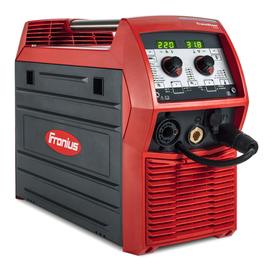
General Device concept The TransSteel (TSt) 2200 power source is a completely digitized, microprocessor- controlled power source. This power source is designed for the wel- ding of steel and can be used for the follo- wing welding processes: MIG/MAG welding Manual metal arc welding TIG welding with touch-down ignition The central control and regulation unit of the power source is coupled with a digital signal... -
Page 26: Application Areas
Application areas MIG/MAG welding TIG welding Manual metal arc welding... -
Page 27: Warning Notices On The Device
Warning notices Warning notices and safety symbols are affixed to the power source. These warning notic- on the device es and safety symbols must not be removed or painted over. They warn against incorrect operation, as this may result in serious injury and property damage. Steel: 3-4 CrNi: 3-4 FCW: 3... - Page 28 Dispose of old devices in accordance with safety rules and not in normal domestic waste. Keep hands, hair, loose clothing, and tools away from moving parts, such as: gears feed rollers wirespools and welding wires. Do not reach into rotating gears of the wire drive or into rotating drive parts. Covers and side parts must only be opened/removed during maintenance and repair work.
-
Page 29: Description Of Warning Notices On The Device
Description of On certain device versions, warning notices are attached to the device. Warning Notices on the Device The arrangement of the symbols may vary. Warning! Watch Out! There are possible hazards as shown by the symbols. Drive rolls can injure fingers. Welding wire and drive parts are at welding voltage during operation Keep hands and metal objects away. - Page 30 Welding sparks can cause explosion or fire. Keep flammables away from welding. Don’t weld near flammables. Welding sparks can cause fires.Have a fire extinguisher nearby and have a watch- person ready to use it. Do not weld on drums or any closed containers. Arc rays can burn eyes and injure skin.
-
Page 31: Operating Controls And Connections
Operating controls and connections... -
Page 33: Control Panel
Control Panel General As a result of software updates, you may find that there are functions available on your de- vice that are not described in these Operating Instructions, or vice versa. Certain illustrations may also differ slightly from the actual controls on your device, but these controls function in exactly the same way. - Page 34 Hold indicator At the end of each welding operation, the actual values for welding current and welding voltage are stored - the "HOLD" indicator lights up Intermediate arc indicator A spatter-prone intermediate arc occurs between the dip transfer arc and the spray arc.
- Page 35 Function "Parameter selection" button (left) For selecting the parameters listed below The relevant symbol lights up when a welding parameter is selected. Sheet thickness in mm or inch *) If the welding current to be selected is not known, it is sufficient to enter the sheet thickness.
- Page 36 Function "Parameter selection" button (right) For selecting the parameters listed below The relevant symbol lights up when a welding parameter is selected. Arc length correction For correcting the arc length Welding voltage in V *) Before the start of welding, the device automatically displays a standard value based on the programmed parameters.
- Page 37 (10) (11) Function Gas-test button For setting the required gas flow rate on the gas pressure regulator/for filling the torch hosepack with shielding gas. When the "Gas-test" button is pressed, shielding gas will flow for 30 s. Press the button again to stop the gas flow prematurely. Adjusting dial (left) For changing the sheet thickness, welding current and wire speed parameters as well as changing parameters in the Setup menu...
-
Page 38: Keylock
(12) (18) (13) (14) (15) (16) (17) Function (12) "Material" button For selecting the filler metal to be used (13) "Save" button 1 For saving an EasyJob (14) "Mode" button For selecting the operating mode 2 T = 2-step mode 4 T = 4-step mode S 4 T = Special 4-step mode Spot welding/stitch welding... - Page 39 Release the "Mode" and "Parameter selection" buttons Keylock activated: The message "CLO | SEd" appears on the displays. Keylock deactivated: The message "OP | En" appears on the displays.
-
Page 40: Connections, Switches, And Mechanical Components
Connections, Switches, and Mechanical Compo- nents Safety WARNING! Danger from incorrect operation and work that is not carried out properly. Serious personal injury and damage to property may result. ► Read and understand this document. ► Read and understand all the Operating Instructions for the system components, espe- cially the safety rules. -
Page 41: Side View
MIG/MAG shielding gas connec- (6) (7) tion socket For the shielding gas supply to the welding torch connection (1) Power switch to switch the power source on and Mains cable with strain relief de- vice Not prefitted on all models TIG shielding gas connection For the shielding gas supply to the (-) - current socket (2) -
Page 43: Before Installation And Initial Operation
Before installation and initial opera- tion... -
Page 45: General
General Safety WARNING! Danger from incorrect operation and work that is not carried out properly. Serious personal injury and damage to property may result. ► All the work and functions described in this document must only be carried out by trained and qualified personnel. -
Page 46: Grid Connection
Grid Connection The devices are designed for the grid voltage stated on the rating plate. If the mains cable or mains plug has not been attached to your version of the appliance, these must be in- stalled according to national standards. Fuse protection for the grid lead can be found in the technical data. -
Page 47: Generator-Powered Operation
Generator-Powered Operation Generator-pow- The power source is generator-compatible. ered operation The maximum apparent power S of the power source must be known in order to select 1max the correct generator output. The maximum apparent power S of the power source is calculated as follows: 1max 1max 1max... -
Page 48: Mains Fuse Protection
Mains Fuse Protection Adjustable mains The mains fuse protection selected on the power source limits the power drawn in from the fuse protection mains and in turn the possible welding current. This prevents the automatic circuit breaker (e.g., in the fuse box) from tripping straight away. The desired mains fuse protection can be selected on the power source depending on the mains voltage and automatic circuit breaker used. - Page 49 TSt 2200 MV: Mains Country- Power source fuse Welding current limitation voltage specific set- rating ting 120 V 15 A MIG/MAG welding: max. 105 A; 80 A at 100 %* MMA welding: max. 90 A; 70 A at 100 %* TIG welding: max.
- Page 50 rent to switch off, the service code "toF" is displayed. A countdown immediately appears next to the "toF" indicator, which shows the remaining time until the power source is ready for welding again. After this time, the message disappears and the power source can be used again.
-
Page 51: Carrying Strap Option
Carrying Strap Option... -
Page 53: Fitting The Carrying Strap
Fitting the Carrying Strap Fitting the carry- ing strap to the power source... -
Page 55: Mig/Mag
MIG/MAG... -
Page 57: Commissioning
Commissioning Connecting a Before connecting the welding torch to the power source, equip the welding torch ac- MIG/MAG welding cording to the welding torch Operating Instructions: Fit wearing parts to the torch body, torch fit the inner liner. Unscrew the knurled screw (1) slightly so that the welding torch can be easily pushed into the welding torch connection. -
Page 58: Inserting The Feed Rollers
Inserting the feed In order to achieve optimum wire electrode feed, the feed rollers must be suitable for the rollers diameter and alloy of the wire being welded. -
Page 59: Inserting The D100 Wirespool
Inserting the D100 wirespool Inserting the D200 wirespool CAUTION! Danger from placing the locking ring the wrong way round. Personal injury and damage to property may result. ► Always position and tighten the locking ring as shown below. -
Page 60: Feeding In The Wire Electrode
Feeding in the CAUTION! wire electrode Danger from springiness of spooled wire electrode. It can cause injuries. ► When inserting the wire electrode into the wire drive, hold the end of the wire electrode firmly. It is only necessary to connect the mains cable to the power source for multivoltage power sources. -
Page 61: Setting The Contact Pressure
CAUTION! Danger from wire electrode emerging unexpectedly as it is being threaded. It can cause injuries. ► Wear suitable protective goggles ► Keep the tip of the welding torch away from your face and body ► Do not point the tip of the welding torch at people ►... -
Page 62: Connecting The Gas Cylinder
Standard values for contact pressure with smooth feed rollers: Steel = 3 - 4 CrNi = 3 - 4 Standard values for contact pressure with toothed feed rollers: Tubular covered electrodes = 3 Aluminum = 1 - 3 Connecting the WARNING! gas cylinder Danger from gas cylinders falling over. -
Page 63: Connecting The Polarity Reverser And Establishing A Grounding (Earthing) Connection
Connecting the polarity reverser NOTE! and establishing a grounding Risk from incorrectly connected polarity (earthing) con- reverser. nection This can result in poor-quality weld proper- ties. ► Connect the polarity reverser according to the wire electrode used. Check the wire electrode packaging to determine whether the wire electrode is for (+) or (-) welding... -
Page 64: Adjusting The Brake Of The Wirespool Holders
Adjusting the Brake of the Wirespool Holders General D200 wirespool holder: Adjust the brake when using the wirespool holder for the first time and after changing the wirespool. To do so, proceed as described in the following section "Adjusting the brake of the D200 wirespool holder". -
Page 65: Adjusting The Brake Of The D200 Wirespool Holder
Adjusting the CAUTION! brake of the D200 wirespool holder Danger from emerging wire electrode and moving parts. Personal injury and damage to property may result. ► Before starting work, turn the mains switch of the power source to - O - and disconnect the power source from the mains ►... -
Page 66: Description Of Mig/Mag Operating Modes
Description of MIG/MAG Operating Modes 2-step mode "2-step mode" is suitable for Tacking work Short weld seams 2-step mode Explanation of symbols: Hold the torch trigger Press the torch trigger Release the torch trigger Abbreviations used Gas pre-flow time Welding current Gas post-flow time 4-step mode "4-step mode"... -
Page 67: Special 4-Step Mode
4-step mode Explanation of symbols: Press the torch trigger Release the torch trigger Abbreviations used Gas pre-flow time Welding current Gas post-flow time Special 4-step "Special 4-step mode" is ideal for welding in higher power ranges. In special 4-step mode, mode the arc starts at a low power, which makes it easier to stabilize. -
Page 68: Spot Welding
Hold the torch trigger Press the torch trigger Release the torch trigger Abbreviations used Gas pre-flow time Starting current Slope: continuous increasing / lowering of welding current Main current Final current Gas post-flow time Spot welding The "Spot welding" mode is suitable for welded joints on overlapped sheets. Spot welding Explanation of symbols: Press the torch trigger... -
Page 69: 2-Step Stitch Welding
2-step stitch The "2-step stitch welding" mode is suitable for welding short weld seams on thin sheets, welding to prevent the weld seams from dropping through the base material. 2-step stitch welding Explanation of symbols: Press the torch trigger Hold the torch trigger Release the torch trigger Abbreviations used Gas pre-flow time... - Page 70 4-step stitch welding Explanation of symbols: Press the torch trigger Release the torch trigger Abbreviations used Gas pre-flow time Welding current Spot welding time / interval welding time Interval pause time Gas post-flow time...
-
Page 71: Mig/Mag Standard Manual Welding
MIG/MAG Standard Manual Welding General The MIG/MAG standard manual welding process is a MIG/MAG welding process with no synergic function. Changing one parameter does not result in any automatic adjustments to the other param- eters – all variable parameters must be adjusted individually. Available parame- The following parameters are available for MIG/MAG manual welding: ters... -
Page 72: Mig/Mag Standard Synergic Welding
MIG/MAG Standard Synergic Welding MIG/MAG stan- Press the "Process" button to select SYNERGIC dard synergic welding Press the "Mode" button to select the desired MIG/MAG mode: 2-step mode 4-step mode S 4 T - Special 4-step mode Spot welding/stitch welding Under certain circumstances, it may not be possible to change welding parameters that have been set for a system component (remote control, etc.) on the control panel of the power source. -
Page 73: Spot And Stitch Welding
Spot and Stitch Welding General The spot and stitch welding modes are MIG/MAG welding processes. Spot welding is used on welded joints on overlapping sheets that are only accessible on one side. Stitch welding is used for light-gage sheets. As the wire electrode is not fed continuously, the weld pool can cool down during the inter- vals. -
Page 77: Commissioning
Commissioning Start-Up... -
Page 78: Tig Welding
It is only necessary to connect the mains cable to the power source for multivoltage power sources. CAUTION! Danger due to welding processes star- ting unintentionally. Personal injury and damage to property may result. ► As soon as the power source is swit- ched on, ensure that the tungsten elec- trode does not accidentally, or in an uncontrolled manner, touch any electri-... -
Page 80: Description Of Tig Operating Modes
Description of TIG Operating Modes 2-step mode down Welding in 2-step mode: Place the tungsten electrode onto the workpiece and then pull the torch trigger back and hold => shielding gas flows Raise the tungsten electrode => arc ignites Release torch trigger => end of welding Explanation of symbols: Release the torch trigger forwards Pull back the torch trigger and hold it in this position... -
Page 81: 4-Step Mode
4-Step Mode down 4-step mode with intermediate lowering I-2 Intermediate lowering means that the welder uses the torch trigger during the main current phase to lower the welding current to the specified reduced current I-2. Welding with 4-step mode: Place the tungsten electrode onto the workpiece and then pull the torch trigger back and hold =>... - Page 82 UpSlope phase: the welding current is continually increased Duration: 0.5 seconds Final current duration DownSlope phase: the welding current is continuously reduced down Duration: 0.5 seconds...
-
Page 83: Pulse Welding
Pulse Welding Applications Pulse welding is welding with a pulsing welding current. It is used to weld steel pipes out- of-position or to weld thin sheet metal. In these applications, the welding current set at the start of welding is not always optimum for the entire welding process: If the amperage is too low, the parent material will not be melted enough If overheating occurs, there is a danger that the liquid weld pool may drip... -
Page 84: Activating Pulse Welding
Activating Pulse Set a value for the F-P setup parameter (pulse frequency) Welding Setting range: 1 - 990 Hz... -
Page 85: Rod Electrode
Rod Electrode... -
Page 87: Commissioning
Commissioning Preparation Check the rod electrode packaging to de- termine whether the rod electrode is for (+) or (-) welding It is only necessary to connect the mains cable to the power source for multivoltage power sources. -
Page 88: Manual Metal Arc Welding
CAUTION! Danger due to welding processes star- ting unintentionally. Personal injury and damage to property may result. ► As soon as the power source is swit- ched on, ensure that the rod electrode does not accidentally, or in an uncont- rolled manner, touch any electrically conductive or grounded parts (e.g., the housing, etc.). -
Page 89: Functions For Optimizing The Welding Process
Functions for Optimizing the Welding Process Arc-Force Dy- Arc-force dynamic: namic For influencing the short-circuiting dynamic at the instant of droplet transfer = hard, stable arc = neutral arc = soft, low-spatter arc HotStart (Hti) This function is activated at the factory. Function Advantages Improved ignition properties, even when using electrodes with poor ignition properties... -
Page 91: Easyjobs
EasyJobs... -
Page 93: Saving And Retrieving Easyjobs
Saving and Retrieving EasyJobs General The "Save" buttons allow two EasyJobs to be saved The adjustable parameters on the control panel are saved Setup parameters are not saved at this time Saving an Easy- Press and hold one of the "Save" buttons to save the current settings on the control panel, e.g., Number 1 The left indicator displays "Pro"... -
Page 95: Setup Menu
Setup Menu... -
Page 97: Setup Menu Level 1
Setup Menu Level 1 Operation Accessing the Setup menu is described with reference to the MIG/MAG standard synergic (SYNERGIC) welding process. Access is the same for the other welding processes. Accessing the Setup menu Press the "Process" button to select SYNERGIC (to access the Setup menu for MIG/ MAG standard manual welding, press the "Process"... -
Page 98: Parameters For Mig/Mag Standard Manual Welding
Parameters for Gas pre-flow time MIG/MAG Stan- Unit: seconds dard Manual Setting range: 0 - 9.9 Welding Factory setting: 0.1 Gas post-flow time Unit: seconds Setting range: 0 - 9.9 Factory setting: 0.5 Feeder inching speed Unit: m/min (ipm) Setting range: 1 - 18.5 (39.37 - 728.35) Factory setting: 10 (393.7) Ignition current Unit: Ampere... -
Page 99: Parameters For Mig/Mag Standard Synergic Welding
Parameters for Gas pre-flow time MIG/MAG Stan- Unit: seconds dard Synergic Setting range: 0 - 9.9 Welding Factory setting: 0.1 Gas post-flow time Unit: seconds Setting range: 0 - 9.9 Factory setting: 0.5 Slope Unit: seconds Setting range: 0 - 9.9 Factory setting: 1 Starting current Unit: % of welding current... - Page 100 Factory setting: OFF Interval Unit: - Setting range: 2T (2-step), 4T (4-step) Factory setting: 2T (2-step) Reset power source to factory settings Press and hold one of the "Parameter selection" buttons for two seconds to restore the factory settings - when "PrG" appears on the digital display, the power source has been reset. When the power source is reset, the majority of the applied settings are deleted.
-
Page 101: Parameters For Tig Welding
Parameters for Pulse frequency TIG Welding Unit: Hertz Setting range: OFF; 1 - 990 (up to 10 Hz: in 0.1 Hz increments) (up to 100 Hz: in 1 Hz increments) (over 100 Hz: in 10 Hz increments) Factory setting: OFF UpSlope Unit: seconds Setting range: 0.01 - 9.9... -
Page 102: Parameters For Mma Welding
Parameters for HotStart current MMA Welding Unit: % Setting range: 100 - 200 Factory setting: 150 Hot current time Unit: seconds Setting range: 0 - 2.0 Factory setting: 0.5 Anti-stick function Unit: - Setting range: On, OFF Factory setting: On Reset power source to factory settings Press and hold one of the "Parameter selection"... -
Page 103: Setup Menu 2Nd Level
Setup Menu 2nd Level Operation Accessing the Setup menu Press the "Process" button to select SYNERGIC (to access the Setup menu for MIG/ MAG standard manual welding, press the "Process" button and select the MANUAL welding process) Press and hold the "Mode" button Press the "Process"... -
Page 104: Parameters For Mig/Mag Welding
Release the "Mode" and "Process" buttons A parameter is displayed in the first level of the Setup menu Press and hold the "Mode" button Press the "Process" button Release the "Mode" and "Process" buttons Parameters for Country-specific setting (Standard/USA) Std/US MIG/MAG welding Unit: - Setting range: Std, US (Standard/USA) -
Page 105: Parameters For Mig/Mag Welding
Welding circuit inductivity (in microhenrys) See section "Displaying welding circuit inductivity L" Real Energy Input Unit: kJ Setting range: ON / OFF Factory setting: OFF Since the full range of values (1 kJ - 99999 kJ) cannot be displayed on the three- digit display, the following display format has been selected: Value in kJ: 1 to 999 / indicator on display: 1 to 999 Value in kJ: 1000 to 9999 / indicator on display: 1.00 to 9.99 (without unit digit,... - Page 106 Real Energy Input Unit: kJ Setting range: ON / OFF Factory setting: OFF Since the full range of values (1 kJ - 99999 kJ) cannot be displayed on the three- digit display, the following display format has been selected: Value in kJ: 1 to 999 / indicator on display: 1 to 999 Value in kJ: 1000 to 9999 / indicator on display: 1.00 to 9.99 (without unit digit, e.g., 5270 kJ ->...
-
Page 107: Parameters For Tig Welding (Setup Menu 2Nd Level)
Parameters for Cooling unit control TIG Welding (Set- (only with TST 3500c MP and if cooling unit is connected) up Menu 2nd Level) Unit: - Setting range: Aut, On, OFF Factory setting: Aut Aut: The cooling unit cuts out after a 2-minute welding off-time. IMPORTANT! If the coolant temperature and flow monitoring options have been installed in the cooling unit, the cooling unit cuts out as soon as the return-flow tem- perature drops below 50 °C, but at the earliest after a 2-minute welding off-time. -
Page 108: Parameters For Manual Metal Arc Welding (Setup Menu 2Nd Level)
SEt parameter set as Std: OFF / 10 / 13 / 16 SEt parameter set as US: OFF / 15 / 20 (only for 120 V grid voltage) Factory setting: OFF Parameters for Country-specific setting (Standard/USA) ... Std/US Manual Metal Arc Welding (Setup Unit: - Menu 2nd Level) -
Page 109: Optimizing Weld Quality
Optimizing Weld Quality... -
Page 111: Measuring The Welding Circuit Resistance R
Measuring the Welding Circuit Resistance r General Measuring the welding circuit resistance r makes it possible to have a constant welding re- sult at all times, even with hosepacks of different lengths. The welding voltage at the arc is then always precisely regulated, regardless of the length and cross-sectional area of the hosepack. -
Page 112: Displaying The Welding Circuit Inductivity L
Displaying the Welding Circuit Inductivity L General The way that the hosepack is arranged has a very significant effect on the welding circuit inductivity and therefore affects the welding process. It is important to lay the hosepacks correctly in order to obtain the best possible welding result. Displaying the The setup parameter "L"... -
Page 113: Troubleshooting And Maintenance
Troubleshooting and Maintenance... -
Page 115: Displaying Service Parameters
Displaying Service Parameters Service parame- Various service parameters can be retrieved by pressing the left and right-hand "Parame- ters ter selection" buttons at the same time. Opening the display Press and hold the "Parameter selection" button (left) Press the "Parameter selection" button (right) Release the "Parameter selection"... -
Page 116: Troubleshooting
Troubleshooting Safety WARNING! Danger from incorrect operation and work that is not carried out properly. Serious personal injury and damage to property may result. ► All the work and functions described in this document must only be carried out by trained and qualified personnel. - Page 117 No welding current Mains switch is on, one of the overtemperature service codes "to" is displayed. Detailed information on the service codes "to0" to "to6" can be found in the section "Displayed ser- vice codes". Cause: Overloading Remedy: Check duty cycle Cause: Thermostatic automatic circuit breaker has been tripped Remedy:...
- Page 118 Irregular wire speed Cause: Braking force has been set too high Remedy: Loosen the brake Cause: Contact tip hole too narrow Remedy: Use suitable contact tip Cause: Faulty inner liner in welding torch Remedy: Check the inner liner for kinks, dirt, etc. and replace if necessary Cause: Feed rollers not suitable for wire electrode used Remedy:...
-
Page 119: Displayed Service Codes
Displayed Service If an error message that is not described here appears on the displays, proceed as follows Codes to resolve the problem: Turn the power source mains switch to the "O" position Wait 10 seconds Turn the mains switch to the "I" position If the error occurs again despite several attempts to eliminate it, or if the troubleshooting measures listed here are unsuccessful: Make a note of the error message displayed... - Page 120 to2 | xxx Note: xxx stands for a temperature value Cause: Overtemperature in the secondary circuit of the power source Remedy: Allow power source to cool down, check air filter and clean if necessary, check that fan is on to3 | xxx Note: xxx stands for a temperature value Cause: Overtemperature on the PC board LSTMAG20 (wirefeeder)
- Page 121 tu0 | xxx Note: xxx stands for a temperature value Cause: Undertemperature on the PC board (secondary circuit) Remedy: Place power source in a heated room and allow it to warm up tu2 | xxx Note: xxx stands for a temperature value Cause: Undertemperature in the power source secondary circuit Remedy:...
- Page 122 no | IGn Cause: "Ignition time-out" function is active; current did not start flowing before the length of wire specified in the Setup menu had been fed. The power source safety cut-out has tripped Remedy: Shorten the wire stick-out; press the torch trigger again; clean the surface of the workpiece;...
-
Page 123: Service, Maintenance And Disposal
Service, maintenance and disposal General Under normal operating conditions, the welding system requires only a minimum of care and maintenance. However, several points must be observed in order for the welding sys- tem to remain operational for years to come. Safety WARNING! Danger from incorrect operation and work that is not carried out properly. -
Page 124: As Required, At Least Every Two Months
As required, at least every two months CAUTION! Danger from wet air filter. Damage to property may result ► Ensure that the air filter is dry when it is fitted. Every 6 Months CAUTION! Danger due to the effect of compressed air. This can result in damage to property. -
Page 125: Removing Stiff Drive Rollers
Removing Stiff Drive Rollers Removing a stiff If a drive roller is difficult to remove by hand, the knurled screw on the D100 brake can be drive roller used to remove it. -
Page 127: Technical Data
Technical Data... -
Page 129: General
General Special voltage For devices designed for special voltages, the technical data on the rating plate applies. Explanation of The duty cycle (D.C.) is the period of a ten minute cycle in which the device may be oper- the Term Duty Cy- ated at the stated power without overheating. -
Page 130: Technical Data
Technical Data TSt 2200 Mains voltage (U 230 V Max. effective primary current (I 16 A 1eff Max. primary current (I 26 A 1max Mains fuse 16 A time-delay fuse Max. apparent power (S 5.98 kVA 1max Mains voltage tolerance -20 / +15 % Grid frequency 50/60 Hz... -
Page 131: Tst 2200 Mv
Wire speed 1.5 - 18 m/min 59.06 - 708.66 ipm Wire drive 2-roller drive Wire diameter 0.6 - 1.2 mm 0.025 - 0.047 in. Wirespool diameter max. 200 mm max. 7.87 in. Wirespool weight max. 6.8 kg max. 14.99 lb Max. - Page 132 10 – 230 A Welding current at 10 min/40 °C (104 °F) 30 % 60 % 100 % MIG/MAG 120 V (15 A) 105 A 95 A 80 A 120 V (20 A) 135 A 120 A 105 A 230 V 210 A 170 A 150 A...
- Page 133 Interface to a 230 V, 50 Hz public grid Only applies to USA: If an automatic circuit breaker is used instead of a fuse, the current/time character- istic of the automatic circuit breaker must match that of the mains fuse specified above.
- Page 136 FRONIUS INTERNATIONAL GMBH Vorchdorfer Straße 40, A-4643 Pettenbach, Austria E-Mail: sales@fronius.com www.fronius.com Under www.fronius.com/contact you will find the addresses of all Fronius Sales & Service Partners and locations...
Need help?
Do you have a question about the TransSteel 2200 and is the answer not in the manual?
Questions and answers