Fronius TransTig 2200 Operating Instructions Manual
Tig power source
Hide thumbs
Also See for TransTig 2200:
- Operating instructions manual (287 pages) ,
- Operating instructions manual (112 pages) ,
- Operating instructions manual (220 pages)
Table of Contents
Advertisement
Quick Links
/ Perfect Charging /
Perfect Welding
TransTig 2200
TransTig 2500 / 3000
TransTig 4000 / 5000
MagicWave 1700 / 2200
MagicWave 2500 / 3000
MagicWave 4000 / 5000
42,0426,0027,EN 018-23022017
Fronius prints on elemental chlorine free paper (ECF) sourced from certified sustainable forests (FSC).
/ Solar Energy
Operating Instructions
Spare parts list
TIG Power source
Advertisement
Table of Contents
Troubleshooting

Related Manuals for Fronius TransTig 2200


Summary of Contents for Fronius TransTig 2200
- Page 1 Spare parts list TransTig 2500 / 3000 TIG Power source TransTig 4000 / 5000 MagicWave 1700 / 2200 MagicWave 2500 / 3000 MagicWave 4000 / 5000 42,0426,0027,EN 018-23022017 Fronius prints on elemental chlorine free paper (ECF) sourced from certified sustainable forests (FSC).
- Page 3 Thank you for the trust you have placed in our company and congratulations on buying this high-quality Fronius product. These instructions will help you familiarise yourself with the product. Reading the instructions carefully will enable you to learn about the many different features it has to offer.
-
Page 5: Table Of Contents
Key combinations - special functions ......................General ..............................Displaying the software version, operating time and coolant flow ............Connections, switches and mechanical components ................MagicWave1700 / 2200 ........................MagicWave2500 / 3000 ........................MagicWave4000 / 5000 ........................TransTig 2200............................TransTig2500 / 3000..........................TransTig4000 / 5000.......................... - Page 6 Installation and commissioning Minimum equipment needed for welding task.................... General ..............................TIG AC welding............................. TIG DC welding............................. MMA welding ............................Before installation and commissioning....................... Safety..............................Utilisation for intended purpose ......................Setup regulations ..........................Mains connection ..........................Generator-powered operation (MW 1700 / 2200, TT2200)..............Connecting up the mains cable on US power sources ................
- Page 7 MagicWave2500 / 3000 ........................100 MagicWave 2500 / 3000 MV......................... 100 MagicWave4000 / 5000 ........................101 MagicWave 4000 / 5000 MV......................... 102 TransTig 2200............................103 TransTig2500 / 3000..........................104 TransTig 2500 / 3000 MV ........................105 TransTig4000 / 5000..........................106 TransTig 4000 / 5000 MV ........................
- Page 8 Circuit diagrams: MagicWave 4000 / MagicWave 5000 ................125 Circuit diagrams: MagicWave 4000 MV / MagicWave 5000 MV..............127 Circuit diagrams: TransTig 2200 ........................ 130 Circuit diagrams: TransTig 2500 / TransTig 2500 MV ................131 Circuit diagrams: TransTig 3000 / TransTig 3000 MV ................132 Circuit diagrams: TransTig 4000 / TransTig 5000..................
-
Page 9: Safety Rules
Safety rules Explanation of DANGER! Indicates immediate and real danger. If it is not avoided, death or se- safety symbols rious injury will result. WARNING! Indicates a potentially dangerous situation. Death or serious injury may result if appropriate precautions are not taken. CAUTION! Indicates a situation where damage or injury could occur. -
Page 10: Proper Use
Proper use The device is to be used exclusively for its intended purpose. The device is intended solely for the welding processes specified on the rating plate. Any use above and beyond this purpose is deemed improper. The manufac- turer shall not be held liable for any damage arising from such usage. Proper use includes: carefully reading and following all the instructions given in the operating instructions... -
Page 11: Obligations Of Personnel
Obligations of Before using the device, all persons instructed to do so undertake: personnel to observe the basic instructions regarding safety at work and accident prevention to read these operating instructions, especially the "Safety rules" section and sign to confirm that they have understood them and will follow them. Before leaving the workplace, ensure that people or property cannot come to any harm in your absence. -
Page 12: Noise Emission Values
Protective clothing refers to a variety of different items. Operators should: protect eyes and face from UV rays, heat and sparks using a protective visor and regulation filter. wear regulation protective goggles with side protection behind the protec- tive visor. wear stout footwear that provides insulation even in wet conditions. -
Page 13: Danger From Flying Sparks
The relevant material safety data sheets and manufacturer's specifications for the listed components should therefore be studied carefully. Flammable vapours (e.g. solvent fumes) should be kept away from the arc's radiation area. Danger from fly- Flying sparks may cause fires or explosions. ing sparks Never weld close to flammable materials. -
Page 14: Meandering Welding Currents
Operating the device on a grid without a ground conductor and in a socket without a ground conductor contact will be deemed gross negligence. The manufacturer shall not be held liable for any damage arising from such usage. If necessary, provide an adequate earth connection for the workpiece. Switch off unused devices. -
Page 15: Emc Measures
EMC measures In certain cases, even though a device complies with the standard limit values for emissions, it may affect the application area for which it was designed (e.g. when there is sensitive equipment at the same location, or if the site where the device is installed is close to either radio or television receivers). - Page 16 During operation Ensure that all covers are closed and all side panels are fitted properly. Keep all covers and side panels closed. The welding wire emerging from the welding torch poses a high risk of injury (piercing of the hand, injuries to the face and eyes, etc.). Therefore always keep the welding torch away from the body (devices with wire-feed unit) and wear suitable protective goggles.
-
Page 17: Factors Affecting Welding Results
Factors affecting The following requirements with regard to shielding gas quality must be met if welding results the welding system is to operate in a correct and safe manner: Size of solid matter particles < 40 μm Pressure dew point < -20 °C Max. -
Page 18: Safety Measures In Normal Operation
Before transporting the device, allow coolant to drain completely and detach the following components: Wire-feed unit Wirespool Shielding gas cylinder After transporting the device, the device must be visually inspected for dam- age before commissioning. Any damage must be repaired by trained service technicians before commissioning the device. -
Page 19: Commissioning, Maintenance And Repair
Commissioning, It is impossible to guarantee that bought-in parts are designed and manufac- maintenance and tured to meet the demands made of them, or that they satisfy safety require- repair ments. Use only original spare and wearing parts (also applies to standard parts). Do not carry out any modifications, alterations, etc. -
Page 20: Safety Symbols
(e.g. relevant product standards from the EN 60 974 series). Fronius International GmbH declares that the device complies with directive 2014/53/EU. The full text of the EU Declaration of Conformity is available from the following website: http://www.fronius.com Devices with the CSA test mark satisfy the requirements of the relevant stand- ards in Canada and the USA. -
Page 21: General Information
General information... -
Page 23: General
A standardised LocalNet interface makes it easy to connect digital system add-ons (e.g. TransTig 2200 Job, MagicWave 1700 Job and JobMaster TIG welding torches, robot weld- MagicWave 2200 Job with cooling unit ing torches, remote control units, etc.). -
Page 24: Functional Principle
Functional princi- The central control and regulation unit of the power sources is coupled with a digital signal processor. The central control and regulation unit and signal processor control the entire welding process. During the welding process, the actual data is measured continuously and the device re- sponds immediately to any changes. -
Page 25: Warning Notices On The Device
Warning notices US power sources come with extra warning notices affixed to the device. The warning no- on the device tices must NOT be removed or painted over. US version of power source with additional warning notices, e.g. MagicWave 2200... -
Page 26: System Components
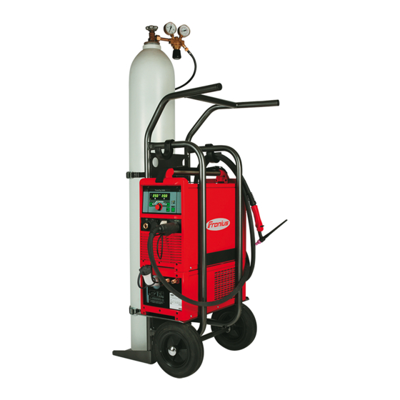
System components General The TransTig and MagicWave power sources can be used with a wide variety of system add-ons and options. Overview System add-ons and options Item Description Power sources Cooling units Trolley with gas cylinder holder Pedal remote control unit TIG welding torch Standard / Up/Down JobMaster TIG welding torch JobMaster TIG welding torch functions in conjunction with power sources:... -
Page 27: Control Elements And Connections
Control elements and connections... -
Page 29: Description Of The Control Panels
Description of the control panels General The key feature of the control panel is the logical way in which the control elements are arranged. All the main welding parameters needed for day-to-day working can easily be: selected using the buttons altered with the adjusting dial shown during welding on the digital display. -
Page 30: Magicwave Control Panel
MagicWave control panel MagicWave con- trol panel (15) (14) (13) (12) (11) (10) No. Function Left digital display HOLD indicator at the end of each welding operation, the actual values for the welding current and voltage are stored and the Hold indicator lights up. The Hold indicator refers to the last value reached by the main current I . - Page 31 No. Function Welding voltage indicator lights up when welding parameter I is selected. During welding the current actual value for the welding voltage is dis- played on the right-hand digital display. Before welding, the following appears on the right digital display: 0.0 if a TIG welding mode is selected 50 V if a MMA welding mode is selected (after a delay of 3 seconds;...
- Page 32 No. Function Gas test button for setting the required shielding gas flow rate on the gas pressure regulator After pressing this button, gas flows for 30 seconds. Press the button again to stop the gas flow prematurely. (10) Welding parameter overview The welding parameters overview contains the most important welding parameters to be used when welding.
- Page 33 No. Function (12) Welding current indicator for indicating the welding current for the welding parameters Starting current I Welding current I Final current I Before welding commences, the left-hand digital display shows the set value. For and I , the right-hand digital display also shows the respective percentage of the welding current I After welding begins, the welding parameter I is automatically selected.
-
Page 34: Transtig Control Panel
TransTig control panel TransTig control panel (14) (13) (12) (11) (10) No. Function Left digital display HOLD indicator at the end of each welding operation, the actual values for the welding current and voltage are stored and the Hold indicator lights up. The Hold indicator refers to the last value reached by the main current I . - Page 35 No. Function Welding voltage indicator lights up when parameter I is selected. During welding the current actual value for the welding voltage is dis- played on the right-hand digital display. Before welding, the following appears on the right digital display: 0.0 if a TIG welding mode is selected 50 V if a MMA welding mode is selected (after a delay of 3 seconds;...
- Page 36 No. Function Welding parameter overview The welding parameters overview contains the most important welding parameters to be used when welding. The sequence of welding parameters follows a clothes- line structure. Use the left and right welding parameter selection buttons to navigate within the welding parameters overview.
- Page 37 No. Function (12) Left parameter selection button for selecting welding parameters within the welding parameters overview (9) When a welding parameter is selected, the LED on the relevant parameter symbol lights up. (13) HF (high frequency) ignition indicator lights up when the HFt set-up parameter has been set to an interval for the high fre- quency pulses (14) Overtemperature indicator lights up if the power source overheats (e.g.
-
Page 38: Key Combinations - Special Functions
Key combinations - special functions General The following functions can be called up by pressing buttons simultaneously or repeatedly on the MagicWave and TransTig control panels. Displaying the To display the software version: software version, while pressing and holding the Mode button, press the left parameter operating time selection button. -
Page 39: Connections, Switches And Mechanical Components
Connections, switches and mechanical components MagicWave 1700 / 2200 MagicWave 1700 / 2200 - front MagicWave 1700 / 2200 - rear No. Function Welding torch connection for connecting: the TIG welding torch the electrode cable for manual metal arc welding LocalNet connection standardised connection socket for system add-ons (e.g. -
Page 40: Magicwave2500 / 3000
MagicWave 2500 / 3000 MagicWave 2500 / 3000 - front MagicWave 2500 / 3000 - rear No. Function Grounding (earthing) cable connection for connecting the grounding (earthing) cable LocalNet connection standardised connection socket for system add-ons (e.g. remote control, JobMas- ter TIG welding torch, etc.) Handle Torch control connection... -
Page 41: Magicwave4000 / 5000
MagicWave 4000 / 5000 (5) (4) (3) MagicWave 4000 / 5000 - front MagicWave 4000 / 5000 - rear No. Function Mains switch for switching the power source on and off Welding torch connection for connecting the TIG welding torch Electrode holder connection for connecting the electrode cable for manual metal arc welding Torch control connection... -
Page 42: Transtig 2200
TransTig 2200 TransTig 800 / 2200 - front TransTig 800 / 2200 - rear No. Function (+) current socket with bayonet latch for connecting the grounding (earthing) cable when TIG welding the electrode cable or grounding (earthing) cable during MMA welding (de-... -
Page 43: Transtig2500 / 3000
TransTig 2500 / 3000 TransTig 2500 / 3000 - front TransTig 2500 / 3000 - rear No. Function (+) current socket with bayonet latch for connecting the grounding (earthing) cable when TIG welding the electrode cable or grounding (earthing) cable during MMA welding (de- pending on the type of electrode) LocalNet connection standardised connection socket for system add-ons (e.g. -
Page 44: Transtig4000 / 5000
TransTig 4000 / 5000 TransTig 4000 / 5000 - front TransTig 4000 / 5000 - rear No. Function (+) current socket with bayonet latch for connecting the grounding (earthing) cable when TIG welding the electrode cable or grounding (earthing) cable during MMA welding (de- pending on the type of electrode) LocalNet connection standardised connection socket for system add-ons (e.g. -
Page 45: Installation And Commissioning
Installation and commissioning... -
Page 47: Minimum Equipment Needed For Welding Task
Minimum equipment needed for welding task General Depending on which welding process you intend to use, a certain minimum equipment lev- el will be needed in order to work with the power source. The welding processes and the minimum equipment levels required for the welding task are then described. -
Page 48: Before Installation And Commissioning
Before installation and commissioning Safety WARNING! Incorrect operation or shoddy workmanship can cause serious injury or damage. All work described in this document must only be carried out by trained and qualified personnel. All functions described in this document must only be used by trained and qualified personnel. -
Page 49: Generator-Powered Operation (Mw 1700 / 2200, Tt2200)
Generator-pow- The MW 1700/2200 and TT 2200 power sources are generator-compatible, provided that ered operation the maximum apparent power delivered by the generator is at least 10 kVA. (MW 1700 / 2200, TT 2200) NOTE The voltage delivered by the generator must never exceed the upper or lower limits of the mains voltage tolerance range. -
Page 50: Connecting Up The Mains Cable On Us Power Sources
Connecting up the mains cable on US power sourc- General The US power sources are supplied without a mains cable. A mains cable appropriate for the connection voltage must be fitted prior to commissioning. A strain-relief device for a cable cross-section AWG 10 is installed on the power source. Strain-relief devices for larger cable cross-sections must be designed accordingly. -
Page 51: Replacing The Strain-Relief Device
Insert the mains cable into the strain- relief device NOTE! Push the mains cable in far enough to make it possible to connect the PE conductor and the phase conductors to the block ter- minal properly. Tighten the clamping nut (size 30 mm) Tighten the screws (2 x) Connect the mains cable to the block terminal correctly:... - Page 52 Slot the large strain-relief device into the housing and fasten it with 2 screws Connecting the mains cable Replace the left side panel of the pow- er source...
-
Page 53: Start-Up
Start-up Safety WARNING! An electric shock can be fatal. If the machine is plugged into the mains electricity supply during installation, there is a high risk of very serious in- jury and damage. Do not carry out any work on the device unless the mains switch is in the "O"... -
Page 54: Establishing A Ground (Earth) Connection To The Workpiece
Screw the pressure regulator onto the gas cylinder and tighten it When using a TIG welding torch with an integral gas connector: Use the gas hose to connect the pressure regulator to the shielding gas connection on the rear of the power source Tighten the union nut on the gas hose When using a TIG welding torch with no integral gas connector: Connect the TIG welding torch gas hose to the pressure regulator... -
Page 55: Welding
Welding... -
Page 57: Tig Modes
TIG modes Safety WARNING! Operating the equipment incorrectly can cause serious injury and damage. Do not use the functions described until you have thoroughly read and understood the following documents: these operating instructions all the operating instructions for the system components, especially the safe- ty rules See the "The Setup menu"... -
Page 58: 2-Step Mode
2-step mode Welding: Pull back and hold the torch trigger End of welding: Release the torch trigger G-L / G-H down 2-step mode 4-step mode Welding start-up with starting current I : Pull back and hold the torch trigger Welding with main current I : Release the torch trigger Lowering to final current I : Pull back and hold the torch trigger... -
Page 59: Special 4-Step Mode: Variant 4
Special 4-step Variant 4 of the special 4-step mode is activated when the SFS set-up parameter is set to mode: "4". variant 4 Welding start-up and welding: briefly pull back and release the torch trigger - the weld- ing current will rise at the specified upslope value from the starting current I until it reaches the main current value I Push forward and hold the torch trigger for intermediate lowering... -
Page 60: Cap Shaping And Cap Overloading
Cap shaping and cap overloading Cap shaping On MagicWave power sources, an auto- matic cap-shaping function is available for the TIG AC welding process: When the TIG AC welding process is selected, activate automatic cap- shaping The ideal cap for the specified diame- ter of the tungsten electrode is formed during welding start-up. -
Page 61: Tig Welding
TIG welding Safety WARNING! Operating the equipment incorrectly can cause serious injury and damage. Do not use the functions described until you have thoroughly read and understood the following documents: these operating instructions all the operating instructions for the system components, especially the safe- ty rules WARNING! An electric shock can be fatal. -
Page 62: Preparation
Balance (only on MagicWave for TIG AC welding process) Unit Setting range -5 to +5 Factory setting -5: highest fusing power, lowest cleaning action +5: highest cleaning action, lowest fusing power Electrode diameter Unit Setting range OFF - max. OFF - max. Factory setting 0.095 Preparation... - Page 63 For long hosepacks and if condensation forms when the device is left unused in a cold environment: purge protective gas shield and set the GPU set-up parameter to a time value Start welding (ignite the arc)
-
Page 64: Igniting The Arc
Igniting the arc General To ensure the best ignition sequence in the TIG AC welding process, the MagicWave pow- er sources take account of: the diameter of the tungsten electrode the current temperature of the tungsten electrode with reference to the preceding welding and weld-off times Igniting the arc HF ignition is activated when a time value has been set for the HFt setup parameter. -
Page 65: Touchdown Ignition
Tilt the torch back into the normal posi- tion Carry out welding Touchdown igni- If the HFt setup parameter is set to OFF, HF ignition is deactivated. The welding arc is ig- tion nited by touching the workpiece with the tungsten electrode. Procedure for igniting the arc using touchdown ignition: Place the gas nozzle down on the igni- tion location so that there is a gap of... -
Page 66: End Of Welding
Raise the welding torch and move it into its normal position The arc ignites. Carry out welding End of welding Depending on the set mode, finish welding by releasing the torch trigger Wait for the set gas post-flow and hold welding torch in position over the end of the weld seam... -
Page 67: Special Functions And Options
Special functions and options Arc break watch- If the arc breaks and the current does not start to flow again within the time specified in the dog function set-up menu, the power source cuts out automatically. The service code "no | Arc" appears on the control panel. - Page 68 IMPORTANT The following points apply to the pulsed welding current: The power source automatically regulates the pulsing parameters as a function of the pre- set main current I The pulsed welding current begins: after the end of the starting-current phase I with the upslope phase UPS Depending on what tAC time has been set, the pulsed welding current may continue up to and including the final current phase I...
-
Page 69: Mma Welding
MMA welding Safety WARNING! Operating the equipment incorrectly can cause serious injury and damage. Do not use the functions described until you have thoroughly read and understood the following documents: these operating instructions all the operating instructions for the system components, especially the safe- ty rules WARNING! An electric shock can be fatal. -
Page 70: Hotstart Function
NOTE! The TransTig power source has no switchover facility between the MMA DC- and MMA DC+ welding processes. Procedure with TransTig power source for switching from MMA DC- welding to MMA DC+ welding: Move the mains switch to the O position Disconnect the mains plug Reconnect the electrode holder and the earthing (grounding) cable to the oppo- site current sockets (i.e. -
Page 71: Anti-Stick Function
Settings examples: HCU = 100 The HotStart current corresponds to the set welding current I The hotstart function is not activated. HCU = 170 The HotStart current is 70% higher than the set welding current I The hotstart function is activated. HCU = 200 The HotStart current is twice the set welding current I The hotstart function is activated, the HotStart current is at its maximum. -
Page 73: Setup Settings
Setup settings... -
Page 75: The Setup Menu
The Setup menu General The set-up menu provides easy access to the knowledge base in the power source and to additional functions. The set-up menu can be used to make simple adjustments of the welding parameters to suit the various job settings. The following can be found in the set-up menu: Set-up parameters that have an immediate effect on the welding process Set-up parameters needed for making the preliminary settings on the welding system... -
Page 76: Shielding Gas Setup Menu
Shielding gas setup menu General The Protective gas shield set-up menu provides easy access to the protective gas shield settings. Opening the Pro- Press and hold the "Mode" button tective gas shield set-up menu Press the Gas test button The power source is now in the Protective gas shield set-up menu. The last welding parameter selected is displayed. - Page 77 Factory setting The value set for G-H only applies if the maximum welding current actually has been set. The actual value is derived from the present welding current. For a medium welding cur- rent, for example, the actual value will be half of the value set for G-H. IMPORTANT! The values set for the G-L and G-H set-up parameters are added together.
-
Page 78: Tig Setup Menu
TIG setup menu Opening the TIG Press the Mode button to select 2-step mode or 4-step mode set-up menu Press and hold the "Mode" button Press the right parameter selection button The power source is now in the TIG set-up menu. The last welding param- eter selected is displayed. - Page 79 Cooling unit control (option) Unit Setting range Aut / ON / OFF Factory setting Cooling unit is switched off 2 minutes after the end of welding Cooling unit is ON all the time Cooling unit is OFF all the time IMPORTANT! If the coolant unit is provided with the optional "thermostat", the coolant re- turn temperature is checked continuously.
- Page 80 Reduced current - Intermediate lowering of the welding current in order to prevent any local overheating of the base material (4-step mode). Unit % (of main current I Setting range 0 - 100 Factory setting AC frequency Unit Setting range Syn / 40 - 250 Factory setting for mains synchronisation of two power sources for simultaneous...
-
Page 81: Rod Electrode Setup Menu
Rod electrode setup menu Open the rod Press the Mode button to select the MMA welding mode electrode set-up menu Press and hold the "Mode" button Press the right parameter selection button The power source is now in the rod electrode set-up menu. The last weld- ing parameter selected is displayed. - Page 82 dYn - arc force dynamic correction Unit Setting range 0 - 100 Factory setting soft, low-spatter arc harder, more stable arc To obtain optimum welding results, it will sometimes be necessary to adjust the arc-force dynamic. Functional principle: at the instant of droplet transfer or when a short circuit occurs, there is a momentary rise in amperage.
-
Page 83: Rod Electrode Setup Menu: Level 2
Rod electrode setup menu: level 2 Opening the rod Open the rod electrode set-up menu electrode set-up Select "2nd" welding parameter menu level 2 Press and hold the "Mode" button Press the right parameter selection button The power source is now in the rod electrode set-up menu - level 2. The last welding parameter selected is displayed. - Page 84 Load line for rod electrode Load line for rod electrode where arc length is in- con - 20 A / V U (V) creased Load line for rod electrode where arc length is re- duced Characteristic where "CON" parameter is select- ed (constant welding current) Characteristic where "0.1 - 20"...
- Page 85 Load line for rod electrode Load line for rod electrode where arc length is in- creased U (V) Load line for rod electrode where arc length is re- duced Characteristic where "CON" parameter is select- ed (constant welding current) Characteristic where "0.1 - 20" parameter is se- lected (drooping characteristic with adjustable slope) Characteristic where "P"...
-
Page 87: Troubleshooting And Maintenance
Troubleshooting and maintenance... -
Page 89: Troubleshooting
Troubleshooting General The digital power sources are equipped with an intelligent safety system. This means that apart from the fuse for the coolant pump, it has been possible to dispense with fuses en- tirely. After a possible malfunction or error has been remedied, the power source can be put back into normal operation again without any fuses having to be replaced. - Page 90 tP3 | xxx Note: xxx stands for a temperature value Cause: Overtemperature in the primary circuit of the power source Remedy: Allow power source to cool down tP4 | xxx Note: xxx stands for a temperature value Cause: Overtemperature in the primary circuit of the power source Remedy: Allow power source to cool down tP5 | xxx...
- Page 91 Err | 052 Cause: Mains overvoltage: The mains voltage has exceeded the upper limit of the tol- erance range (see section "Technical data") Remedy: Check the mains voltage no | IGn Cause: "Ignition time-out" function is active; current did not start flowing before the length of wire specified in the set-up menu had been fed.
-
Page 92: Power Source - Troubleshooting
hot | H2O Cause: Thermostat on cooling unit has tripped Remedy: Wait until the end of the cooling phase, i.e. until "Hot | H2O" is no longer dis- played. ROB 5000 or field bus coupler for robot control: Before resuming welding, in- itialise the "Source error reset"... - Page 93 No protective gas shield All other functions are OK Cause: Gas cylinder is empty Remedy: Change the gas cylinder Cause: Gas pressure regulator is faulty Remedy: Change the gas pressure regulator Cause: Gas hose is not fitted or is damaged Remedy: Fit or change the gas hose Cause:...
-
Page 94: Care, Maintenance And Disposal
Care, maintenance and disposal General Under normal operating conditions, the power source requires only a minimum of care and maintenance. However, it is vital to observe some important points to ensure it remains in a usable condition for many years. Safety WARNING! Work that is carried out incorrectly can cause serious injury or dam- age. -
Page 95: Disposal
Disposal Dispose of in accordance with the applicable national and local regulations. -
Page 97: Appendix
Appendix... -
Page 99: Technical Data
Technical data Special voltages NOTE! An inadequately dimensioned electrical installation can cause serious damage. The mains cable and its fuse must be dimensioned accordingly. The technical data shown on the rating plate applies. MagicWave MW 1700 MW 2200 1700 / 2200 Mains voltage 230 V 230 V... -
Page 100: Magicwave2500 / 3000
MagicWave MW 2500 MW 3000 2500 / 3000 Mains voltage 3 x 400 V 3 x 400 V Mains voltage tolerance ± 15 % ± 15 % Mains frequency 50/60 Hz 50/60 Hz Mains fuse protection (slow-blow) 16 A 16 A Mains connection at PCC at PCC... -
Page 101: Magicwave4000 / 5000
MW 2500 MV MW 3000 MV Primary continuous power (100% d.c. 3 x 400 - 460 V 4.8 kVA 5.1 kVA 3 x 200 - 240 V 4.4 kVA 4.9 kVA 1 x 200 - 240 V 3.9 kVA 4.3 kVA Cos phi 0,99 0,99... -
Page 102: Magicwave 4000 / 5000 Mv
MW 4000 MW 5000 Mains fuse protection (slow-blow) 35 A 35 A Mains connection Restrictions possible Restrictions possible Primary continuous power (100% d.c. 15.5 kVA 17.9 kVA Cos phi 0,99 0,99 Welding current range 3 - 400 A 3 - 500 A Electrode 10 - 400 A 10 - 440 A... -
Page 103: Transtig 2200
Weight 60 kg 60 kg 132.30 lb. 132.30 lb. Mark of conformity S, CE, CSA S, CE, CSA TransTig 2200 Mains voltage 230 V Mains voltage tolerance -20 % / +15 % Mains frequency 50/60 Hz Mains fuse protection (slow-blow) -
Page 104: Transtig2500 / 3000
The arc striking voltage is suitable for manual operation. Degree of protection IP 23 Type of cooling Insulation class EMC emission class (in accordance with EN/IEC 60974-10) Dimensions L x W x H (with handle) 485 / 180 / 390 mm 19.1 / 7.1 / 15.4 in. -
Page 105: Transtig 2500 / 3000 Mv
TT 2500 TT 3000 Weight 24.2 kg 24.2 kg 53.35 lb. 53.35 lb. Mark of conformity S, CE S, CE TransTig TT 2500 MV TT 3000 MV 2500 / 3000 MV Mains voltage 3 x 200 - 240 V 3 x 200 - 240 V 3 x 400 - 460 V 3 x 400 - 460 V 1 x 200 - 240 V... -
Page 106: Transtig4000 / 5000
TT 2500 MV TT 3000 MV Degree of protection IP 23 IP 23 Type of cooling Insulation class EMC emission class (in accordance with EN/IEC 60974-10) Dimensions L x W x H (with handle) 560 / 250 / 435 mm 560 / 250 / 435 mm 22.0 / 9.8 / 17.1 in. -
Page 107: Transtig 4000 / 5000 Mv
TransTig TT 4000 MV TT 5000 MV 4000 / 5000 MV Mains voltage 3 x 200 - 240 V 3 x 200 - 240 V 3 x 380 - 460 V 3 x 380 - 460 V Mains voltage tolerance ±... -
Page 108: Terms And Abbreviations Used
Terms and abbreviations used General The terms and abbreviations listed here are used in connection with functions that are ei- ther included in the standard scope of supply or that are available as optional extras. Terms and abbre- viations A - F AC frequency Cooling unit control dynamic... -
Page 109: Terms And Abbreviations I - U
Terms and abbre- viations I - U Reduced current (4-step mode with intermediate lowering) Phase Adjustment Phase adjustment of the mains connection of two power sources for simultaneous AC welding Pre Ignition - delayed high frequency ignition Tacking function UpSlope The starting current is continuously increased until it reaches the welding current... -
Page 111: Spare Parts And Circuit Diagrams
Spare parts and circuit diagrams... -
Page 112: Spare Parts List: Tt 800 / 2200 Job, Mw 1700 / 2200 Job, Tt 2200, Mw 1700 / 2200
Spare parts list: TT 800 / 2200 Job, MW 1700 / 2200 Job, TT 2200, MW 1700 / 2200... - Page 113 4,070,813 - BSV22 TT2200 4,070,798,Z - BPS17 MW 1700/TT 800 4,070,804,Z - TTS22 MW1700/2200 4,070,799,Z - BPS22 TT/MW 2200 41,0001,0627 41,0009,0057 33,0024,0032 33,0010,0325 - MW/TT2200 43,0006,0168 43,0001,1191 42,0405,0420 4,070,963,Z - UST-PIPE 4,070,812 - HFF22 43,0004,1122 - 26pol.
-
Page 114: Spare Parts List: Transtig / Magicwave 2500 / 3000
Spare parts list: TransTig / MagicWave 2500 / 3000... - Page 115 43,0004,3830 - 26pol. 4,070,963,Z - UST-PIPE 4,071,201,Z 4,071,068,Z 43,0001,3320 43,0006,0168 43,0006,0168 4,071,063,Z 33,0010,0366 4,071,064,Z - MV 33,0010,0367 4,071,065,Z - MW2500 4,071,066,Z - MW3000 4,071,071 - TT3000 42,0409,3196 - MW 42,0409,3195 - TT 43,0001,3318 - TT 2500/3000 43,0001,3319 - MW 2500/3000 4,070,812,Z - HFF22 33,0010,0377-TT2500 43,0001,3311,Z - MW...
-
Page 116: Spare Parts List: Transtig 4000 / 5000
Spare parts list: TransTig 4000 / 5000... -
Page 118: Spare Parts List: Magicwave 4000 / 5000
Spare parts list: MagicWave 4000 / 5000... -
Page 121: Circuit Diagrams: Magicwave 1700
Circuit diagrams: MagicWave 1700... -
Page 122: Circuit Diagrams: Magicwave 2200
Circuit diagrams: MagicWave 2200 V. 12.06.2014... -
Page 123: Circuit Diagrams: Magicwave 2500 / Magicwave 2500 Mv
Circuit diagrams: MagicWave 2500 / MagicWave 2500 MV... -
Page 124: Circuit Diagrams: Magicwave 3000 / Magicwave 3000 Mv
Circuit diagrams: MagicWave 3000 / MagicWave 3000 MV... -
Page 125: Circuit Diagrams: Magicwave 4000 / Magicwave 5000
Circuit diagrams: MagicWave 4000 / MagicWave 5000 V 17.12.2012... - Page 126 V 17.12.2012...
-
Page 127: Circuit Diagrams: Magicwave 4000 Mv / Magicwave 5000 Mv
Circuit diagrams: MagicWave 4000 MV / MagicWave 5000 MV... -
Page 130: Circuit Diagrams: Transtig 2200
Circuit diagrams: TransTig 2200 V 14.12.2010... -
Page 131: Circuit Diagrams: Transtig 2500 / Transtig 2500 Mv
Circuit diagrams: TransTig 2500 / TransTig 2500 MV... -
Page 132: Circuit Diagrams: Transtig 3000 / Transtig 3000 Mv
Circuit diagrams: TransTig 3000 / TransTig 3000 MV... -
Page 133: Circuit Diagrams: Transtig 4000 / Transtig 5000
Circuit diagrams: TransTig 4000 / TransTig 5000 V 17.12.2012... -
Page 134: Circuit Diagrams: Transtig 4000 Mv / Transtig 5000 Mv
Circuit diagrams: TransTig 4000 MV / TransTig 5000... - Page 140 FRONIUS INTERNATIONAL GMBH Froniusplatz 1, A-4600 Wels, Austria Tel: +43 (0)7242 241-0, Fax: +43 (0)7242 241-3940 E-Mail: sales@fronius.com www.fronius.com www.fronius.com/addresses Under http://www.fronius.com/addresses you will find all addresses of our Sales & service partners and Locations...
Need help?
Do you have a question about the TransTig 2200 and is the answer not in the manual?
Questions and answers