Fronius TransPocket 4000 CEL Operating Instructions Manual
Rod electrode power source
Hide thumbs
Also See for TransPocket 4000 CEL:
- Operating instructions & spare parts (163 pages) ,
- Operating instructions manual (172 pages)
Table of Contents
Advertisement
Available languages
Available languages
Quick Links
Perfect Welding
/ Perfect Charging /
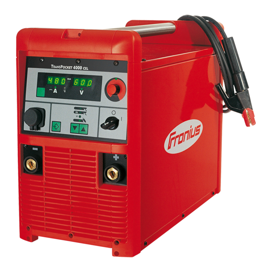
TransPocket 4000 CEL,
TransPocket 5000 CEL
42,0410,0781
Fronius prints on elemental chlorine free paper (ECF) sourced from certified sustainable forests (FSC).
/ Solar Energy
001-11032020
Bedienungsanleitung
Stabelektroden-Stromquelle
Operating Instructions
Rod electrode power source
Instructions de service
Source de courant électrodes
Advertisement
Chapters
Table of Contents

Related Manuals for Fronius TransPocket 4000 CEL


Summary of Contents for Fronius TransPocket 4000 CEL
- Page 1 / Solar Energy Bedienungsanleitung TransPocket 4000 CEL, TransPocket 5000 CEL Stabelektroden-Stromquelle Operating Instructions Rod electrode power source Instructions de service Source de courant électrodes 42,0410,0781 001-11032020 Fronius prints on elemental chlorine free paper (ECF) sourced from certified sustainable forests (FSC).
- Page 3 Fronius Produkt. Die vorliegende Anleitung hilft Ihnen, sich mit diesem vertraut zu machen. Indem Sie die Anleitung sorgfältig lesen, lernen Sie die viel- fältigen Möglichkeiten Ihres Fronius Produktes kennen. Nur so können Sie seine Vorteile bestmöglich nutzen. Bitte beachten Sie auch die Sicherheitsvorschriften und sorgen Sie so für mehr Sicherheit am Einsatzort des Produktes.
-
Page 5: Table Of Contents
Inhaltsverzeichnis Sicherheitsvorschriften..........................Erklärung Sicherheitshinweise......................Allgemeines ............................Bestimmungsgemäße Verwendung...................... Umgebungsbedingungen........................Verpflichtungen des Betreibers......................Verpflichtungen des Personals ......................Netzanschluss............................Fehlerstrom-Schutzschalter ........................Selbst- und Personenschutz ......................... Angaben zu Geräuschemissions-Werten ..................... Gefahr durch schädliche Gase und Dämpfe..................Gefahr durch Funkenflug ........................Gefahren durch Netz- und Schweißstrom..................... Vagabundierende Schweißströme...................... - Page 6 Funktion Hot-Start..........................Funktion Eln (Kennlinienauswahl)......................Funktion Anti-Stick ..........................WIG-Schweißen............................Sicherheit .............................. WIG-Schweißen............................ Option TIG-Comfort-Stop........................Das Setup-Menü: Ebene 1......................... Allgemeines ............................In das Setup-Menü für Parameter Verfahren einsteigen ..............Parameter ändern ..........................Das Setup-Menü verlassen........................Parameter ..............................Stabelektroden-Schweißen........................WIG-Schweißen............................ Das Setup-Menü: Ebene 2......................... Allgemeines ............................
-
Page 7: Sicherheitsvorschriften
Sicherheitsvorschriften Erklärung Sicher- GEFAHR! heitshinweise Bezeichnet eine unmittelbar drohende Gefahr. ► Wenn sie nicht gemieden wird, sind Tod oder schwerste Verletzungen die Folge. WARNUNG! Bezeichnet eine möglicherweise gefährliche Situation. ► Wenn sie nicht gemieden wird, können Tod und schwerste Verletzungen die Folge sein. -
Page 8: Bestimmungsgemäße Verwendung
Bestimmungsge- Das Gerät ist ausschließlich für Arbeiten im Sinne der bestimmungsgemäßen Verwendung mäße Verwen- zu benutzen. dung Das Gerät ist ausschließlich für die am Leistungsschild angegebenen Schweißverfahren bestimmt. Eine andere oder darüber hinaus gehende Benutzung gilt als nicht bestimmungsgemäß. Für hieraus entstandene Schäden haftet der Hersteller nicht. Zur bestimmungsgemäßen Verwendung gehört auch das vollständige Lesen und Befolgen aller Hinweise aus der Bedienungsanleitung das vollständige Lesen und Befolgen aller Sicherheits- und Gefahrenhinweise... -
Page 9: Netzanschluss
Vor Verlassen des Arbeitsplatzes sicherstellen, dass auch in Abwesenheit keine Perso- nen- oder Sachschäden auftreten können. Netzanschluss Geräte mit hoher Leistung können auf Grund ihrer Stromaufnahme die Energiequalität des Netzes beeinflussen. Das kann einige Gerätetypen betreffen in Form von: Anschluss-Beschränkungen Anforderungen hinsichtlich maximal zulässiger Netzimpedanz Anforderungen hinsichtlich minimal erforderlicher Kurzschluss-Leistung jeweils an der Schnittstelle zum öffentlichen Netz... -
Page 10: Angaben Zu Geräuschemissions-Werten
Personen, vor allem Kinder, während des Betriebes von den Geräten und dem Schweiß- prozess fernhalten. Befinden sich dennoch Personen in der Nähe diese über alle Gefahren (Blendgefahr durch Lichtbogen, Verletzungsgefahr durch Funkenflug, gesundheitsschädlicher Schweißrauch, Lärmbelastung, mögliche Ge- fährdung durch Netz- oder Schweißstrom, ...) unterrichten, geeignete Schutzmittel zur Verfügung stellen oder geeignete Schutzwände und -Vorhänge aufbauen. -
Page 11: Gefahr Durch Funkenflug
Wird nicht geschweißt, das Ventil der Schutzgas-Flasche oder Hauptgasversorgung schließen. Gefahr durch Funkenflug kann Brände und Explosionen auslösen. Funkenflug Niemals in der Nähe brennbarer Materialien schweißen. Brennbare Materialien müssen mindestens 11 Meter (36 ft. 1.07 in.) vom Lichtbogen ent- fernt sein oder mit einer geprüften Abdeckung zugedeckt werden. Geeigneten, geprüften Feuerlöscher bereithalten. -
Page 12: Vagabundierende Schweißströme
Wird das Gerät an einem Netz ohne Schutzleiter und an einer Steckdose ohne Schutzlei- ter-Kontakt betrieben, gilt dies als grob fahrlässig. Für hieraus entstandene Schäden haftet der Hersteller nicht. Falls erforderlich, durch geeignete Mittel für eine ausreichende Erdung des Werkstückes sorgen. -
Page 13: Emv-Maßnahmen
EMV-Maßnahmen In besonderen Fällen können trotz Einhaltung der genormten Emissions-Grenzwerte Be- einflussungen für das vorgesehene Anwendungsgebiet auftreten (z.B. wenn empfindliche Geräte am Aufstellungsort sind oder wenn der Aufstellungsort in der Nähe von Radio- oder Fernsehempfängern ist). In diesem Fall ist der Betreiber verpflichtet, angemessene Maßnahmen für die Störungs- behebung zu ergreifen. - Page 14 Während des Betriebes Sicherstellen, dass alle Abdeckungen geschlossen und sämtliche Seitenteile ord- nungsgemäß montiert sind. Alle Abdeckungen und Seitenteile geschlossen halten. Austritt des Schweißdrahtes aus dem Schweißbrenner bedeutet ein hohes Verletzungsri- siko (Durchstechen der Hand, Verletzung von Gesicht und Augen, ...). Daher stets den Schweißbrenner vom Körper weghalten (Geräte mit Drahtvorschub) und eine geeignete Schutzbrille verwenden.
-
Page 15: Anforderung An Das Schutzgas
Anforderung an Insbesondere bei Ringleitungen kann verunreinigtes Schutzgas zu Schäden an der Aus- das Schutzgas rüstung und zu einer Minderung der Schweißqualität führen. Folgende Vorgaben hinsichtlich der Schutzgas-Qualität erfüllen: Feststoff-Partikelgröße < 40 µm Druck-Taupunkt < -20 °C max. Ölgehalt < 25 mg/m³ Bei Bedarf Filter verwenden! Gefahr durch Schutzgas-Flaschen enthalten unter Druck stehendes Gas und können bei Beschädigung... -
Page 16: Sicherheitsmaßnahmen Im Normalbetrieb
Keine aktiven Geräte heben oder transportieren. Geräte vor dem Transport oder dem He- ben ausschalten! Vor jedem Transport des Gerätes, das Kühlmittel vollständig ablassen, sowie folgende Komponenten demontieren: Drahtvorschub Drahtspule Schutzgas-Flasche Vor der Inbetriebnahme, nach dem Transport, unbedingt eine Sichtprüfung des Gerätes auf Beschädigungen vornehmen. -
Page 17: Inbetriebnahme, Wartung Und Instandsetzung
Elektromagnetischen Verträglichkeits-Richtlinie (z.B. relevante Produkt- normen der Normenreihe EN 60 974). Fronius International GmbH erklärt, dass das Gerät der Richtlinie 2014/53/EU entspricht. Der vollständige Text der EU-Konformitätserklärung ist unter der folgenden Internet-Ad- resse verfügbar: http://www.fronius.com Mit dem CSA-Prüfzeichen gekennzeichnete Geräte erfüllen die Anforderungen der rele-... -
Page 18: Datensicherheit
Datensicherheit Für die Datensicherung von Änderungen gegenüber den Werkseinstellungen ist der An- wender verantwortlich. Im Falle gelöschter persönlicher Einstellungen haftet der Hersteller nicht. Urheberrecht Das Urheberrecht an dieser Bedienungsanleitung verbleibt beim Hersteller. Text und Abbildungen entsprechen dem technischen Stand bei Drucklegung. Änderungen vorbehalten. -
Page 19: Allgemeines
Schweißprozess. Laufend werden die Ist-Daten gemessen, auf Veränderungen wird sofort reagiert. Die von Fronius entwickelten Regel-Algorithmen sorgen dafür, dass der jeweils gewünschte Soll- Zustand erhalten bleibt. Dadurch ergeben sich eine bisher unvergleichliche Präzision im Schweißprozess, exakte Reproduzierbarkeit sämtlicher Ergebnisse und hervorragende Schweißeigenschaften. -
Page 20: Bedienelemente Und Anschlüsse
Bedienelemente und Anschlüsse Allgemeines Das Bedienpanel ist von den Funktionen her logisch aufgebaut. Die einzelnen für die Schweißung notwendigen Parameter lassen sich einfach mittels Taste anwählen und mit dem Einstellrad verändern während der Schweißung am Display anzeigen Auf Grund von Softwareupdates können Funktionen an Ihrem Gerät verfügbar sein, die in dieser Bedienungsanleitung nicht beschrieben sind oder umgekehrt. - Page 21 Taste Parameteranwahl zur Anwahl folgender Parameter Schweißstrom Dynamik Leuchtet die Anzeige an der Taste Parameteranwahl und am Einstellrad, kann der angezeigte / angewählte Parameter mit dem Einstellrad abgeändert werden. Die Parameter können für sämtliche Verfahren, welche mittels Taste Verfahren (3) anwählbar sind, gesondert eingestellt werden.
-
Page 22: Anschlüsse
(11) Anzeige Übertemperatur leuchtet auf, wenn sich die Stromquelle zu stark erwärmt (z.B. durch überschritte- ne Einschaltdauer). Weiterführende Informationen im Kapitel „Fehlerdiagnose und Fehlerbehebung“ (12) Anzeige TP 08 leuchtet auf, wenn an der Stromquelle eine Fernbedienung TP 08 angeschlossen ist. Auch wenn die Fernbedienung TP 08 bereits wieder abgeklemmt wurde, leuchtet die Anzeige TP 08 weiterhin. -
Page 23: Fernbdienung Tr 2000
Fernbdienung TR Einstellregler Schweißstrom 2000 zur Anwahl des Schweißstromes Einstellregler Dynamik zur Beeinflussung der Kurzschluss- Stromstärke im Moment des Trop- fenüberganges 0 weicher und spritzerarmer Licht- bogen 100 härterer und stabilerer Licht bo- Vorder- u. Rückansicht Stromquelle TP 4000 CEL / TP 5000 CEL Parameter, die an der Fernbedienung einstellbar sind, können nicht an der Stromquelle geändert werden. -
Page 24: Fernbdienung Tr 4000
Auswahlschalter Schweißstrom-Bereich zur Auswahl des mittels Einstellregler Schweißstrom (3) einstellbaren Schweiß- strom-Bereiches min - 150 A: 0 geringstmöglicher Schweißstrom 10 Schweißstrom beträgt 150 A 100 A - max: 0 Schweißstrom beträgt 100 A 10 größtmöglicher Schweißstrom Einstellregler Dynamik Stabelektroden-Schweißen ... zur Beeinflussung der Kurzschluss- Stromstärke im Moment des Trop- fenüberganges... -
Page 25: Fernbdienung Tr 1000 / Tr 1100
Einstellregler Hotstart Stabelektroden-Schweißen ... beeinflusst den Schweißstrom während der Zünd- phase 0 keine Beeinflussung 10 100%ige Erhöhung des Schweißstromes während der Zündphase Einstellregler Dynamik Stabelektroden-Schweißen ... zur Beeinflussung der Kurzschluss-Stromstärke im Moment des Tropfenüberganges 0 weicher und spritzerarmer Lichtbogen 100 härterer und stabilerer Lichtbogen WICHTIG! Parameter, die an der Fernbedienung einstellbar sind, können nicht an der Stromquelle geändert werden. - Page 26 Mit Taste „Verfahren“ das Verfahren (7) (2) Stabelektroden-Schweißen anwählen Masseklemme am Werkstück befesti- gen und Elektrodenhalterung an der (5) (6) Fernbedienung TP 08 festklemmen TP 08 auf das Werkstück aufsetzen, so dass eine satte Verbindung zwischen Werkstück und den beiden Kontakten (4) entsteht Fernbedienung TP 08 Die Schweißspannung wird mit einer Verzögerung von 3 s auf die Schweißbuchsen ge-...
-
Page 27: Optionen
Optionen Verteiler „Local- Mit dem Verteiler „LocalNet passiv“ können Net passiv“ am Anschluss LocalNet der Stromquelle mehrere Systemerweiterungen gleichzeitig angeschlossen und betrieben werden - z.B. TR 3000 und TR 1100 gemeinsam. Verteiler „LocalNet passiv“ Verteiler „LocalNet passiv“ funktioniert nur ordnungsgemäß, wenn beide Verteilenden be- nutzt / angeschlossen sind. -
Page 28: Polwender
Polwender Systemvoraussetzung: Software-Version 2.81.1 Fernbedienung TR 3000 Umschalter für Polwender TR 3000 zur Ansteuerung des Polwenders (Option) (+) Positives Schweißpotential an der (+) - Strombuchse (-) Negatives Schweißpotential an der (+) - Strombuchse Ansteuerung des Polwenders in Verbindung mit TR 3000... -
Page 29: Vor Der Inbetriebnahme
Vor der Inbetriebnahme Sicherheit WARNUNG! Gefahr durch Fehlbedienung. Schwerwiegende Personen- und Sachschäden können die Folge sein. ► Beschriebene Funktionen erst anwenden, wenn diese Bedienungsanleitung vollstän- dig gelesen und verstanden wurde. ► Beschriebene Funktionen erst anwenden, wenn sämtliche Bedienungsanleitungen der Systemkomponenten, insbesondere Sicherheitsvorschriften vollständig gelesen und verstanden wurden. - Page 30 HINWEIS! Nicht ausreichend dimensionierte Elektroinstallation kann zu schwerwiegenden Sachschäden führen. Die Netzzuleitung sowie deren Absicherung sind entsprechend der vorhandenen Strom- versorgung auszulegen. Es gelten die Technischen Daten auf dem Leistungsschild.
-
Page 31: Fahrwagen Everywhere Montieren
Fahrwagen Everywhere montieren Sicherheit WARNUNG! Gefahr durch einen elektrischen Schlag. Ist das Gerät während der Installation am Netz angesteckt, besteht die Gefahr schwerwie- gender Personen und Sachschäden. ► Sämtliche Arbeiten am Gerät nur durchführen, wenn der Netzschalter in Stellung - O - geschaltet ist. -
Page 32: Griffteil An Der Stromquelle Montieren
Arretierungen durch Verschieben der äußeren Gewindebolzen (4) bis zum Anschlag gerade stellen Sechs Flügelmuttern (3) festziehen Fahrwagen mit Stromquelle vorsichtig auf die Räder stellen Arretierungen gerade stellen und fixieren Griffteil an der Stromquelle mon- tieren Griffbleche und Griffrohr Griffbleche einrasten lassen WICHTIG! Beim Aneinanderfügen der beiden Griffbleche (1) darauf achten, dass die Ar- retierungen (2), an der Unterseite der Griffbleche (1), vollständig einrasten. -
Page 33: Bedienung Des Griffteiles
Griffbleche (1) mittels vier Schrauben Extrude-Tite (9) und (10) in der Mitte aneinander fixieren Bedienung des WICHTIG! Bei eingefahrenem Griffteil (1) den Griffteil unbedingt, durch Drehen nach links Griffteiles verriegeln. Zum Einfahren des Griffteiles (1): Griffteil nach links drehen (entriegeln) –... -
Page 34: Stabelektroden-Schweißen
Stabelektroden-Schweißen Sicherheit WARNUNG! Gefahr durch Fehlbedienung. Schwerwiegende Personen- und Sachschäden können die Folgen sein. ► Beschriebene Funktionen erst anwenden, wenn folgende Dokumente vollständig ge- lesen und verstanden wurden: ► diese Bedienungsanleitung ► sämtliche Bedienungsanleitungen der Systemkomponenten, insbesondere Sicher- heitsvorschriften WARNUNG! Gefahr durch einen elektrischen Schlag. -
Page 35: Funktion Hot-Start
WICHTIG! Parameter, die an der Fernbedienung TR 2000 / 3000 / 4000 einstellbar sind, können nicht an der Stromquelle geändert werden. Parameteränderungen können nur an der Fernbedienung TR 2000 / 3000 / 4000 erfolgen. Taste Parameteranwahl (2) drücken (Anzeige an der Taste muss leuchten) Mit Einstellrad (1) gewünschte Stromstärke einstellen (Wert kann an der linken Anzei- ge abgelesen werden) Taste Parameteranwahl (2) drücken (Anzeige an der Taste muß... - Page 36 Parameter „0,1 - 20“ (fallende Kennlinie mit einstellbarer Neigung) Mittels Parameter „0,1-20“ kann eine fallende Kennlinie (5) eingestellt werden. Der Ein- stellbereich erstreckt sich von 0,1 A / V (sehr steil) bis 20 A / V (sehr flach). Die Einstellung einer flachen Kennlinie (5) ist nur für Cellulose-Elektroden empfehlenswert.
-
Page 37: Funktion Anti-Stick
(10) (11) 50 100 150 200 250 300 350 400 450 (A) - 50 % Dynamik Einstellbeispiel: I = 250 A, Dynamik = 50 Arbeitsgerade für Stabelektrode Arbeitsgerade für Stabelektrode bei erhöhter Lichtbogen-Länge Arbeitsgerade für Stabelektrode bei reduzierter Lichtbogen-Länge Kennlinie bei angewähltem Parameter „con“ (konstanter Schweißstrom) Kennlinie bei angewähltem Parameter „0,1 - 20“... -
Page 38: Wig-Schweißen
WIG-Schweißen Sicherheit WARNUNG! Gefahr durch Fehlbedienung. Fehlbedienung kann schwerwiegende Personen- und Sachschäden verursachen. ► Beschriebene Funktionen erst anwenden, wenn diese Bedienungsanleitung vollstän- dig gelesen und verstanden wurde. ► Beschriebene Funktionen erst anwenden, wenn sämtliche Bedienungsanleitungen der Systemkomponenten, insbesondere Sicherheitsvorschriften vollständig gelesen und verstanden wurden. -
Page 39: Option Tig-Comfort-Stop
Schweißung durchführen Die zum Schutz von Wolframelektrode und Schweißung erforderliche Gas-Nachstömzeit nach Schweißende hängt vom Schweißstrom ab. Schweißstrom Gas-Nachströmzeit. Schweißstrom Gas-Nachströmzeit 50 A 100 A 150 A 200 A 250 A 12 s 300 A 13 s 350 A 14 s 400 A 16 s Zum Beenden des Schweißvorganges WIG Gasschieber-Brenner vom Werkstück... - Page 40 TIG-Comfort-Stop Schweißen Schweißbrenner heben: Lichtbogen wird deutlich verlängert Schweißbrenner absenken: – Lichtbogen wird deutlich verkürzt Funktion TIG-Comfort-Stop hat ausgelöst – Höhe des Schweißbrenners beibehalten Schweißstrom wird rampenförmig abgesenkt (Downslope) – Lichtbogen erlischt – Gas-Nachströmzeit abwarten und Schweißbrenner vom Werkstück abheben Ablauf WIG-Schweißen bei aktivierter Option TIG-Comfort-Stop Gas-Vorströmung eingestellter Schweißstrom...
-
Page 41: Das Setup-Menü: Ebene 1
Das Setup-Menü: Ebene 1 Allgemeines Es steckt bereits eine Menge an Expertenwissen in den digitalen Stromquellen. Jederzeit kann auf optimierte, im Gerät abgespeicherte Parameter zurückgegriffen werden. Das Setup-Menü bietet einfachen Zugriff auf dieses Expertenwissen sowie einige zusätz- liche Funktionen. Es ermöglicht eine einfache Anpassung der Parameter an die unter- schiedlichen Aufgabenstellungen In das Setup- Die Funktionsweise wird anhand des Verfahrens „Stabelektroden-Schweißen“... -
Page 42: Parameter
Parameter Stabelektroden- Die Funktion HCU (Hotstart-Strom) und der verfügbare Einstellbereich wird im Kapitel Schweißen „Stabelektroden-Schweißen“ beschrieben. Hot-start current - Hotstart-Strom Einheit m/min Einstellbereich 0 - 100 % Werkseinstellung 50 % Hot-current time - Hotstrom-Zeit Einheit Einstellbereich 0 - 2,0 s Werkseinstellung 0,5 s Factory - Stromquelle zurücksetzen... -
Page 43: Das Setup-Menü: Ebene 2
Das Setup-Menü: Ebene 2 Allgemeines Die Funktionen Eln (Kennlinien-Auswahl), r (Schweißkreis-Widerstand), L (Anzeige Schweißkreis-Induktivität) und ASt (Anti-Stick) wurden in einer zweiten Menüebene unter- gebracht. In zweite Menüebene (2nd) wechseln Wie im Kapitel „Das Setup-Menü: Ebene 1“ beschrieben, den Parameter „2nd“ anwäh- Taste Setup / Store (7) drücken und halten Taste Verfahren (3) drücken Taste Setup / Store (7) loslassen... -
Page 44: Parameter 2Nd
Parameter 2nd Allgemeines WICHTIG! Für das Verfahren WIG-Schweißen stehen nur die Parameter r (Schweißkreis- Widerstand) und L (Schweißkreis-Induktivität) zur Verfügung. Parameter 2nd Die Funktion Eln (Kennlinien-Auswahl) kann für die Verfahren „Stabelektroden-Schwei- ßen“, „Stabelektroden-Schweißen mit CEL-Elektrode“ und „Spezial-Verfahren“ gesondert eingestellt werden. Die Einstellung bleibt so lange gespeichert, bis der jeweilige Einstell- wert abgeändert wird. -
Page 45: Schweißkreis-Widerstand R Ermitteln
Schweißkreis-Widerstand r ermitteln Allgemeines Durch die Ermittlung des Schweißkreis-Widerstand r ist es möglich, auch bei unterschied- lichen Schweißkabel-Längen immer ein gleichbleibendes Schweißergebnis zu erzielen; die Schweißspannung am Lichtbogen ist unabhängig von Schweißkabel-Länge und - Querschnitt immer exakt geregelt. Der Schweißkreis-Widerstand wird nach der Ermittlung an der rechten Display angezeigt. r ... -
Page 46: Schweißkreis-Induktivität L Anzeigen
Schweißkreis-Induktivität L anzeigen Schweißkreis-In- Die Verlegung der Schweißkabel hat we- duktivität L anzei- sentliche Auswirkungen auf die Schweißei- genschaften. Abhängig von Länge und Verlegung der Schweißkabel, kann eine hohe Schweißkreis-Induktivität entstehen - der Stromanstieg während des Tropfen- überganges wird begrenzt. Die Schweißkreis-Induktivität L wird wäh- rend des Schweißvorganges errechnet und am rechten Display angezeigt. -
Page 47: Fehlerdiagnose, Fehlerbehebung
Fehlerdiagnose, Fehlerbehebung Sicherheit Die digitalen Stromquellen sind mit einem intelligenten Sicherheitssystem ausgestattet; auf die Verwendung von Schmelzsicherungen konnte daher zur Gänze verzichtet werden. Nach der Beseitigung einer möglichen Störung kann die Stromquelle - ohne den Wechsel von Schmelzsicherungen - wieder ordnungsgemäß betrieben werden. WARNUNG! Gefahr durch einen elektrischen Schlag. -
Page 48: Stromquelle Tp 4000 Cel / Tp 5000 Cel
Err | 051 Ursache: Netz-Unterspannung: Netzspannung hat den Toleranzbereich (+/- 15%) un- terschritten Behebung: Netzspannung kontrollieren Err | 052 Ursache: Netz-Überspannung: Netzspannung hat den Toleranzbereich (+/- 15%) über- schritten Behebung: Netzspannung kontrollieren Err | PE Ursache: Die Erdstrom-Überwachung hat die Sicherheitsabschaltung der Stromquelle ausgelöst. - Page 49 kein Schweißstrom Netzschalter eingeschaltet, Anzeigen leuchten Ursache: Masseanschluss falsch Behebung: Masseanschluss und Klemme auf Polarität überprüfen Ursache: Stromkabel im WIG Gasschieber-Brenner unterbrochen Behebung: WIG Gasschieber-Brenner tauschen kein Schutzgas alle anderen Funktionen vorhanden Ursache: Gasflasche leer Behebung: Gasflasche wechseln Ursache: Gas-Druckminderer defekt Behebung: Gas-Druckminderer tauschen Ursache: Gasschlauch nicht montiert oder schadhaft...
- Page 50 Stromquelle hat keine Funktion Netzschalter eingeschaltet, Anzeigen leuchten nicht Ursache: Netzzuleitung unterbrochen, Netzstecker nicht eingesteckt Behebung: Netzzuleitung überprüfen, ev. Netzstecker einstecken Ursache: Netzabsicherung Behebung: Netzabsicherung wechseln Ursache: Netz-Steckdose oder Netzstecker defekt Behebung: defekte Teile austauschen kein Schweißstrom Netzschalter eingeschaltet, Anzeige Übertemperatur leuchtet Ursache: Überlastung, Einschaltdauer überschritten Behebung: Einschaltdauer berücksichtigen...
-
Page 51: Pflege, Wartung Und Entsorgung
Pflege, Wartung und Entsorgung Allgemeines Die Stromquelle benötigt unter normalen Betriebsbedingungen nur ein Minimum an Pflege und Wartung. Das Beachten einiger Punkte ist jedoch unerlässlich, um die Schweißanlage über Jahre hinweg einsatzbereit zu halten. WARNUNG! Ein elektrischer Schlag kann tödlich sein. Vor Öffnen des Gerätes ►... -
Page 52: Technische Daten
Technische Daten Allgemeines Ist die Stromquelle für eine Sonderspannung ausgelegt, gelten die Technischen Daten am Leistungsschild. Netzstecker, Netzzuleitung sowie deren Absicherung sind entsprechend auszulegen TP 4000 CEL Netzspannung 3 x 400 V Netzspannungs-Toleranz +/- 15 % Netzabsicherung 35 A träge Netzanschluss Beschränkungen möglich Primär-Dauerleistung... -
Page 53: Tp 5000 Cel
Schweißstrom Bereich Stabelektrode 10 - 380 A 10 - 380 A Schweißstrom bei 10 min / 40 °C 40 % ED 380 A 10 min / 40 °C 60 % ED 360 A 10 min / 40 °C 100 % ED 320 A genormte Arbeitsspannung Stabelektrode... -
Page 54: Tp 5000 Cel Mv
An öffentliche Stromnetze mit 230/400 V und 50 Hz ED = Einschaltdauer TP 5000 CEL MV Netzspannung 3 x 200 - 400 V 3 x 380 - 460 V Netzspannungs-Toleranz +/- 10 % Netzabsicherung 200 - 240 V: 63 A 380 - 460 V: 35 A Netzanschluss Beschränkungen möglich... - Page 55 Thank you for the trust you have placed in our company and congratulations on buying this high-quality Fronius product. These instructions will help you familiarise yourself with the product. Reading the instructions carefully will enable you to learn about the many different features it has to offer.
- Page 57 Contents Safety rules ..............................Explanation of safety notices ........................ General ..............................Proper use ............................Environmental conditions........................Obligations of the operator........................Obligations of personnel ........................Mains connection ..........................Residual current protective device......................Protecting yourself and others ......................Noise emission values .......................... Danger from toxic gases and vapours ....................
- Page 58 HotStart function ........................... Eln function (characteristic selection) ....................Anti-stick function..........................TIG welding..............................Safety..............................TIG welding............................TIG Comfort Stop option ........................Setup menu: level 1 ........................... General ..............................Accessing the Setup menu for Process parameters................Changing welding parameters ......................Exiting the Setup menu......................... Parameters ..............................
-
Page 59: Safety Rules
Safety rules Explanation of DANGER! safety notices Indicates immediate danger. ► If not avoided, death or serious injury will result. WARNING! Indicates a potentially hazardous situation. ► If not avoided, death or serious injury may result. CAUTION! Indicates a situation where damage or injury could occur. ►... -
Page 60: Environmental Conditions
The device is intended solely for the welding processes specified on the rating plate. Any use above and beyond this purpose is deemed improper. The manufacturer shall not be held liable for any damage arising from such usage. Proper use includes: carefully reading and following all the instructions given in the operating instructions studying and obeying all safety and danger notices carefully performing all stipulated inspection and maintenance work. -
Page 61: Residual Current Protective Device
This may affect a number device types in terms of: Connection restrictions Criteria with regard to the maximum permissible mains impedance Criteria with regard to the minimum short-circuit power requirement at the interface with the public grid see "Technical data" In this case, the plant operator or the person using the device should check whether the device may be connected, where appropriate by discussing the matter with the power sup- ply company. -
Page 62: Danger From Toxic Gases And Vapours
It is not possible to provide a workplace-related emission value during welding (or cutting) as this is influenced by both the process and the environment. All manner of different weld- ing parameters come into play, including the welding process (MIG/MAG, TIG welding), the type of power selected (DC or AC), the power range, the type of weld metal, the resonance characteristics of the workpiece, the workplace environment, etc. -
Page 63: Risks From Mains Current And Welding Current
Welding must not be performed in areas that are subject to fire or explosion or near sealed tanks, vessels or pipes unless these have been prepared in accordance with the relevant national and international standards. Do not carry out welding on containers that are being or have been used to store gases, propellants, mineral oils or similar products. -
Page 64: Meandering Welding Currents
Meandering weld- If the following instructions are ignored, meandering welding currents can develop with the ing currents following consequences: Fire hazard Overheating of parts connected to the workpiece Irreparable damage to ground conductors Damage to device and other electrical equipment Ensure that the workpiece is held securely by the workpiece clamp. -
Page 65: Emf Measures
Supporting measures for avoidance of EMC problems: Mains supply If electromagnetic interference arises despite correct mains connection, addition- al measures are necessary (e.g. use a suitable line filter). Welding power leads must be kept as short as possible must run close together (to avoid EMF problems) must be kept well apart from other leads Equipotential bonding Earthing of the workpiece... -
Page 66: Requirement For The Shielding Gas
Power sources for work in areas with increased electric risk (e.g. near boilers) must carry the "Safety" sign. However, the power source must not be located in such areas. Risk of scalding from escaping coolant. Switch off cooling unit before disconnecting cool- ant flow or return lines. -
Page 67: Safety Measures At The Installation Location And During Transport
Only use shielding gas cylinders suitable for the application in hand, along with the correct and appropriate accessories (regulator, hoses and fittings). Only use shielding gas cylin- ders and accessories that are in good condition. Turn your face to one side when opening the valve of a shielding gas cylinder. Close the shielding gas cylinder valve if no welding is taking place. -
Page 68: Commissioning, Maintenance And Repair
Always fasten the shielding gas cylinder securely and remove it beforehand if the device is to be transported by crane. Only the manufacturer's original coolant is suitable for use with our devices due to its prop- erties (electrical conductibility, anti-freeze agent, material compatibility, flammability, etc.). Only use suitable original coolant from the manufacturer. -
Page 69: Disposal
(e.g. relevant product standards of the EN 60 974 se- ries). Fronius International GmbH hereby declares that the device is compliant with Directive 2014/53/EU. The full text on the EU Declaration of Conformity can be found at the following address: http://www.fronius.com... -
Page 70: General
The actual data is measured continuously and the machine responds immediately to any changes. The rule algorithms developed by Fronius ensure that the specified target status is maintained. This gives the welding process an unrivalled degree of precision, with exact reproducibility of all results and excellent weld properties. -
Page 71: Control Elements And Connections
Control elements and connections General The functions are all arranged in a logical way on the control panel. The various welding parameters can easily be selected with the press of a button and can just as easily be changed using the adjusting dial shown on the display during welding As a result of software updates, you may find that your device has certain functions that are not described in these Operating Instructions, or vice versa. - Page 72 Parameter selection button for selecting the following parameters Welding current Arc-force dynamic If the indicator is lit up on the parameter selection button and on the adjusting dial, then the indicated / selected parameter can be altered using the adjusting dial. The parameters can be set separately for all welding processes that can be select- ed using the Process button (3).
-
Page 73: Connections
(11) Overtemperature indicator Lights up if the power source overheats (e.g. because the duty cycle has been ex- ceeded). For more information on this, see the "Troubleshooting" section. (12) TP 08 indicator Lights up when a TP 08 remote control is connected to the power source. Even if the TP 08 remote control has already been disconnected, the TP 08 indi- cator remains lit. -
Page 74: Tr 2000 Remote Control
TR 2000 remote Welding current adjuster control For selecting the welding current Arc-force dynamic adjuster For influencing the short-circuiting amperage at the instant of droplet transfer 0 soft, low-spatter arc 100 harder, more stable arc Front and rear view of TP 4000 CEL / TP 5000 CEL po- wer source Parameters which can be adjusted on the remote control cannot be altered on the power source. -
Page 75: Tr 4000 Remote Control
Welding current range selector switch For selecting the welding current range that can be set using the welding current adjuster (3) min - 150 A: 0 minimum welding current 10 welding current is 150 A 100 A - max: 0 welding current is 100 A 10 maximum welding current Arc-force dynamic adjuster Manual metal arc welding ... -
Page 76: Tr 1000 / Tr 1100 Remote Control
HotStart adjuster Manual metal arc welding ... influences the welding current during the ignition phase 0 no influence 10 100% increase in the welding current during the ignition phase Arc-force dynamic adjuster Manual metal arc welding ... for influencing the short-circuiting amperage at the in- stant of droplet transfer 0 soft, low-spatter arc 100 harder, more stable arc... - Page 77 Press the "Process" button to select (7) (2) the MMA welding process Secure the earthing clamp to the work- piece and clamp the electrode holder to the TP 08 remote control (5) (6) Place the TP 08 on the workpiece so that a tight connection is created bet- ween the workpiece and the two con- tacts (4)
-
Page 78: Options
Options "LocalNet pas- With the "LocalNet passive" distributor, se- sive" distributor veral system add-ons can be connected to the LocalNet connection of the power source and operated simultaneously, e.g. the TR 3000 and TR 1100 together. "LocalNet passive" distributor The "LocalNet passive" distributor only functions correctly if both distributor ends are used/ connected. -
Page 79: Polarity Reverser
Polarity reverser System requirements: Software version 2.81.1 TR 3000 remote control Changeover switch for polarity TR 3000 reverser For controlling the polarity reverser (option) (+) Positive welding potential on the (+) current socket (-) Negative welding potential on the (+) current socket Control of the polarity reverser in conjunction with TR 3000... -
Page 80: Before Commissioning
Before commissioning Safety WARNING! Danger from incorrect operation. This can result in serious injury and damage to property. ► Do not use the functions described here until you have read and completely under- stood these Operating Instructions. ► Do not use the functions described here until you have fully read and understood all of the Operating Instructions for the system components, in particular the safety rules. -
Page 81: Mounting The Everywhere Trolley
Mounting the Everywhere trolley Safety WARNING! Risk of electric shock. If the device is plugged into the mains during installation, there is a high risk of serious in- jury and damage to property. ► Only carry out work on the device if the mains switch is in the "O" position. ►... -
Page 82: Fitting The Handle To The Power Source
Straighten the locking devices by mo- ving the outer threaded bolts (4) as far as they will go Tighten the six wing nuts (3) Carefully place the trolley with power source on its wheels Straighten the locking devices and secure them Fitting the handle to the power source... -
Page 83: Operating The Handle
Operating the IMPORTANT! When the handle (1) is retracted, it is essential to lock the handle by turning handle it to the left. To retract the handle (1): Turn the handle to the left (unlock) – – Turn the handle to the left again (lock) IMPORTANT! When the handle (1) is ex- tended, it is essential to lock the handle by turning it to the right. -
Page 84: Mma Welding
MMA welding Safety WARNING! Danger from incorrect operation. This can result in serious injury and damage to property. ► Do not use the functions described here until you have fully read and understood the following documents: ► These Operating Instructions ►... -
Page 85: Hotstart Function
Press the "Parameter selection" button (2) (indicator on the button must light up) Set the desired amperage using the adjusting dial (1) (value can be read off from the left-hand indicator) Press the "Parameter selection" button (2) (indicator on the button must light up) Set the desired arc-force dynamic using the adjusting dial (1) (value can be read off from the left-hand indicator) Start welding... - Page 86 "P" parameter (constant welding power) If the "P" parameter is set, the welding power is kept constant, irrespective of the welding voltage and welding current. This results in a hyperbolic characteristic (6). The "P" parameter is particularly suitable for cellulose electrodes. The "P" parameter is therefore also the factory setting when the "MMA welding with Cel electrode"...
-
Page 87: Anti-Stick Function
(10) (11) 50 100 150 200 250 300 350 400 450 (A) - 50 % Dynamik Settings example: I = 250 A, arc-force dynamic = 50 Load line for rod electrode Load line for rod electrode where arc length is increased Load line for rod electrode where arc length is reduced Characteristic where "con"... -
Page 88: Tig Welding
TIG welding Safety WARNING! Danger from incorrect operation. Operating the equipment incorrectly can cause serious injury and damage. ► Do not use the functions described here until you have read and completely under- stood these Operating Instructions. ► Do not use the functions described here until you have fully read and understood all of the Operating Instructions for the system components, in particular the safety rules. -
Page 89: Tig Comfort Stop Option
Carry out welding After the end of welding, the gas post-flow time required to protect the tungsten electrode and the welding operation depends on the welding current. Welding current gas post-flow time Welding current Gas post-flow time 50 A 100 A 150 A 200 A 250 A... - Page 90 TIG Comfort Stop Welding Raise the welding torch: the arc length is increased significantly Lower the welding torch: – The arc length is decreased significantly The TIG Comfort Stop function is triggered – Keep the welding torch at the same height The welding current is continuously decreased (downslope) –...
-
Page 91: Setup Menu: Level 1
Setup menu: level 1 General The digital power sources come with a wealth of expert knowledge already built in. You can retrieve and use any of the optimised parameters stored in the machine whenever you wish. The Setup menu provides simple access to this expert knowledge plus some additional functions. -
Page 92: Parameters
Parameters MMA welding The HCU (HotStart current) function and available setting range are described in the sec- tion headed "MMA welding". HotStart current Unit m/min Setting range 0 - 100% Factory setting Hot-current time Unit Setting range 0 - 2.0 s Factory setting 0.5 s Factory - reset power source... -
Page 93: Setup Menu: Level 2
Setup menu: level 2 General The Eln (characteristic selection), r (welding circuit resistance), L (welding circuit inductivity display) and ASt (anti-stick) functions are located in a second menu level. Changing to the second menu level (2nd) Select the "2nd" parameter as described in the section "Setup menu: level 1" Press and hold the Setup / Store (7) button Press the Process button (3) Release the Setup / Store (7) button... -
Page 94: 2Nd Parameter
2nd parameter General IMPORTANT! Only parameters r (welding circuit resistance) and L (welding circuit induc- tivity) are available for TIG welding. 2nd parameter The Eln function (characteristic selection) can be configured separately for the processes "MMA welding", "MMA welding with Cel electrode" and "Special processes". The setting is stored until the respective set value is changed. -
Page 95: Measuring Welding Circuit Resistance R
Measuring welding circuit resistance r General Measuring the welding circuit resistance "r" makes it possible to have a constant welding result at all times, even with different welding cable lengths. The welding voltage at the arc is then always precisely regulated, regardless of the welding cable length and cross sec- tion. -
Page 96: Displaying Welding Circuit Inductivity L
Displaying welding circuit inductivity L Displaying weld- The way that the welding power-leads are ing circuit induc- routed has a very significant effect on the tivity L weld properties. Depending on the length and routing of the welding power-leads, a high welding circuit inductivity can occur –... -
Page 97: Troubleshooting
Troubleshooting Safety The digital power sources are equipped with an intelligent safety system, which has made it possible to dispense with melting-type fuses entirely. After a possible malfunction or error has been remedied, the power source can be put back into normal operation again without any fuses having to be replaced. -
Page 98: Tp 4000 Cel / Tp 5000 Cel Power Source
Err | 049 Cause: Phase failure Remedy: Check the mains fuse, the mains lead and the mains plug Err | 051 Cause: Mains undervoltage: The mains voltage has fallen below the tolerance range (+/- 15%) Remedy: Check the mains voltage Err | 052 Cause: Mains overvoltage: The mains voltage has exceeded the tolerance range (+/... - Page 99 No welding current Mains switch is on, indicators are lit up Cause: Grounding (earthing) connection is incorrect Remedy: Check the grounding (earthing) connection and terminal for correct polarity Cause: Break in power cable in the TIG gas-valve torch Remedy: Replace TIG gas-valve torch No shielding gas All other functions are OK Cause:...
- Page 100 Power source does not function Mains switch is on, but indicators are not lit up Cause: There is a break in the mains lead; the mains plug is not plugged in Remedy: Check the mains lead, ensure that the mains plug is plugged in Cause: Mains fuse protection Remedy:...
-
Page 101: Care, Maintenance And Disposal
Care, maintenance and disposal General Under normal operating conditions, the power source requires only a minimum of care and maintenance. However, some important points must be noted to ensure that the welding system remains in a usable condition for many years. WARNING! An electric shock can be fatal. -
Page 102: Technical Data
Technical data General If the power source is designed for a special voltage, the technical data on the rating plate applies. The mains plug, mains lead and their fuse protection must be rated accordingly. TP 4000 CEL Mains voltage 3 x 400 V Mains voltage tolerance +/- 15% Mains fuse protection... -
Page 103: Tp 5000 Cel
Welding current at 10 min / 40°C 40% D.C. 380 A 10 min / 40°C 60% D.C. 360 A 10 min / 40 °C 100% D.C. 320 A Standardised working voltage 20.4 - 35.2 V 14.5 - 33 V Maximum working voltage 53 V (380A) 80 V (10 A) Open circuit voltage (pulsed) -
Page 104: Tp 5000 Cel Mv
TP 5000 CEL MV Mains voltage 3 x 200 - 400 V 3 x 380 - 460 V Mains voltage tolerance +/- 10% Mains fuse protection 200 - 240 V: 63 A 380 - 460 V: 35 A Mains connection Restrictions possible Primary continuous power 100% D.C. - Page 105 Nous vous remercions de la confiance que vous nous témoignez et vous félicitons d'avoir acquis ce produit Fronius de haute qualité technique. Les présentes Instructions de service doivent vous permettre de vous familiariser avec ce produit. Par une lecture attentive de ces instructions, vous apprendrez à...
- Page 107 Sommaire Consignes de sécurité ..........................109 Explication des consignes de sécurité ....................109 Généralités............................109 Utilisation conforme à la destination ..................... 110 Conditions environnementales......................110 Obligations de l'exploitant ........................110 Obligations du personnel ........................111 Couplage au réseau..........................111 Disjoncteur à courant résiduel ......................111 Protection de l'utilisateur et des personnes ..................
- Page 108 Fonction Hot-Start..........................138 Fonction Eln (sélection de la courbe caractéristique) ................138 Fonction Anti-Stick ..........................140 Soudage TIG.............................. 141 Sécurité..............................141 Soudage TIG............................141 Option TIG Comfort Stop ........................142 Menu Setup : niveau 1 ..........................144 Généralités............................144 Entrer dans le menu Setup pour accéder aux paramètres Procédés ........... 144 Modifier les paramètres ........................
-
Page 109: Consignes De Sécurité
Consignes de sécurité Explication des DANGER ! consignes de sé- curité Signale un risque de danger immédiat. ► S'il n'est pas évité, il peut entraîner la mort ou des blessures graves. AVERTISSEMENT ! Signale une situation potentiellement dangereuse. ► Si elle n'est pas évitée, elle peut entraîner la mort ou des blessures graves. ATTENTION ! Signale une situation susceptible de provoquer des dommages. -
Page 110: Utilisation Conforme À La Destination
Utilisation Cet appareil est exclusivement destiné aux applications dans le cadre d'un emploi conforme à la conforme aux règles en vigueur. destination L'appareil est exclusivement conçu pour le mode opératoire de soudage indiqué sur la plaque signalétique. Toute autre utilisation est considérée comme non conforme. Le fabricant ne saurait être tenu pour responsable des dommages consécutifs. -
Page 111: Obligations Du Personnel
Obligations du Toutes les personnes qui sont habilitées à travailler avec l'appareil s'engagent, avant de personnel commencer à travailler à respecter les dispositions de base relatives à la sécurité du travail et à la prévention des accidents à lire les présentes instructions de service, en particulier le chapitre « Consignes de sécurité... -
Page 112: Données Relatives Aux Valeurs Des Émissions Sonores
Font également partie des vêtements de protection : Protéger les yeux et le visage au moyen d'un écran de protection muni d'une car- touche filtrante conforme avec protection contre les rayons UV, la chaleur et les pro- jections d'étincelles. Derrière l'écran de protection, porter des lunettes de protection conformes avec pro- tection latérale. -
Page 113: Risques Liés À La Projection D'étincelles
Les composants suivants sont, entre autres, responsables du degré de nocivité des fu- mées de soudage : métaux utilisés pour la pièce à souder électrodes revêtements détergents, dégraissants et produits similaires process de soudage utilisé Tenir compte des fiches techniques de sécurité des matériaux et des consignes corres- pondantes des fabricants pour les composants mentionnés. -
Page 114: Intensités De Soudage Vagabondes
triques. Pour les câbles de courant avec prise de courant à baïonnette, tourner le câble de courant d'au moins 180° autour de l'axe longitudinal et le pré-tendre. Ne pas enrouler les câbles et les conduites autour du corps ou de parties du corps. Concernant les électrodes (électrodes enrobées, électrodes en tungstène, fil d'apport, ...) : ne jamais les tremper dans un liquide pour les refroidir ;... -
Page 115: Classification Cem Des Appareils
Pour les applications automatisées MIG/MAG, le cheminement du fil-électrode doit impé- rativement être isolé entre le fût de fil de soudage, la grande bobine ou la bobine de fil et le dévidoir. Classification Les appareils de la classe d'émissions A : CEM des appa- ne sont prévus que pour une utilisation dans les zones industrielles reils... -
Page 116: Mesures Liées Aux Champs Électromagnétiques
Mesures liées aux Les champs électromagnétiques peuvent provoquer des problèmes de santé qui ne sont champs électro- pas encore bien connus : magnétiques Répercussions sur l'état de santé des personnes se trouvant à proximité, par ex. por- teurs de stimulateurs cardiaques et d'appareils auditifs Les porteurs de stimulateurs cardiaques doivent consulter leur médecin avant de pou- voir se tenir à... -
Page 117: Exigences Liées Au Gaz De Protection
Utiliser uniquement les moyens de levage adaptés du fabricant pour le transport par grue des appareils. Accrocher les chaînes ou élingues à tous les points prévus à cet effet sur le moyen de levage adapté. Les chaînes ou les élingues doivent présenter un angle aussi réduit que possible par rapport à... -
Page 118: Mesures De Sécurité Sur Le Lieu D'installation Et Lors Du Transport
Si une soupape d'une bouteille de gaz de protection est ouverte, détourner le visage. Fermer la soupape de la bouteille de gaz de protection si aucun soudage n'est en cours. Laisser le capuchon sur la soupape de la bouteille de gaz de protection si celle-ci n'est pas utilisée. -
Page 119: Mise En Service, Maintenance Et Remise En État
Toujours bien fixer la bouteille de gaz de protection et la retirer avant le transport par grue. Utiliser exclusivement le réfrigérant d'origine du fabricant qui, en raison de ses propriétés (conductivité électrique, protection contre le gel, compatibilité des matériaux, combustibi- lité, ...) est adapté... -
Page 120: Élimination
électromagnétique (par ex. normes produits correspon- dantes de la série de normes EN 60 974). Fronius International GmbH déclare que l'appareil est conforme à la directive 2014/53/UE. Le texte intégral de la déclaration UE de conformité est disponible à l'adresse suivante : http://www.fronius.com... -
Page 121: Généralités
Les données réelles sont mesurées en permanence et les modifications sont prises en compte immédiatement. Les algorithmes de réglage mis au point par Fronius garantissent le maintien de l'état théorique souhaité. Ceci permet une précision incomparable du process de soudage, la reproductibilité exacte de l'ensemble des résultats et des caractéristiques de soudage excellentes. -
Page 122: Éléments De Commande Et Connexions
Éléments de commande et connexions Généralités Les commandes de fonction sont disposées de façon logique sur le panneau de com- mande. Les différents paramètres nécessaires au soudage peuvent être facilement sélec- tionnés à l'aide des touches : modifiés au moyen d'une molette de réglage ; et sont affichés sur l'écran durant le soudage. - Page 123 Touche Sélection de paramètre pour la sélection des paramètres suivants : intensité de soudage ; dynamique. Le paramètre affiché/sélectionné peut être modifié avec la molette de réglage lorsque le témoin de la touche Sélection de paramètre et celui de la molette sont allumés.
-
Page 124: Connecteurs
(11) Voyant Surcharge thermique s'allume lorsque la source de courant chauffe trop (par exemple parce que le fac- teur maximal de marche est dépassé). Vous trouverez de plus amples informations au chapitre « Diagnostic d'erreur, élimination de l'erreur ». (12) Voyant TP 08 s'allume lorsqu'une commande à... -
Page 125: Commande À Distance Tr 2000
Commande à dis- Bouton de réglage de l'intensité tance TR 2000 de soudage pour la sélection de l'intensité de soudage Bouton de réglage de la dynami- pour influencer l'intensité de cou- rant de court-circuit au moment du transfert de goutte 0 arc électrique doux et à... - Page 126 Sélecteur de procédé de souda- pour sélectionner les procédés de soudage : soudage manuel à l'électrode enrobée ; soudage manuel à l'électrode en- robée avec électrode cellulosique ; procédé de soudage spécial ; soudage TIG avec amorçage par Commande à distance TR 3000 – Vue de gauche contact.
-
Page 127: Commande À Distance Tr 4000
Commande à dis- Touche de commutation des pa- tance TR 4000 ramètres pour sélectionner et afficher les pa- ramètres Tension de soudage et In- tensité de soudage sur l'affichage numérique. Lors de la modification d'un para- mètre, la valeur du paramètre est brièvement indiquée par l'affichage numérique de la commande à... -
Page 128: Commande À Distance Tp 08
Touche(s) Affichage de paramè- (2) (1) pour sélectionner le paramètre à af- ficher (intensité de soudage, ...) Touche(s) Réglage de paramètre pour modifier le paramètre sélecti- onné Paramètre Intensité de soudage Principe de fonctionnement TR 1000 / TR 1100 Commande à dis- Configuration du système tance TP 08 version de logiciel 2.81.1... - Page 129 Code de service : -oFF Cause : mauvais contact avec la pièce à souder. Solution Satte Verbindung zum Werkstück herstellen Code de service : -E62- Cause : température supérieure à la normale de la commande à distance TP 08. Solution : TP 08 abkühlen lassen Tant que la source de courant ou une autre extension de système affiche un code de ser- vice, la commande à...
-
Page 130: Options
Options Répartiteur Le répartiteur « LocalNet passif » permet « LocalNet de raccorder et d'exploiter simultanément passif » plusieurs extensions de système sur la con- nexion LocalNet de la source de courant – par ex. TR 3000 et TR 1100 ensemble. Répartiteur «... -
Page 131: Commutateur De Pôle
Commutateur de Configuration du système : pôle version de logiciel 2.81.1 commande à distance TR 3000 Commutateur pour commutateur TR 3000 de pôle pour commander le commutateur de pôle (en option) Potentiel de soudage positif (+) sur le connecteur (+) Potentiel de soudage négatif (-) sur le connecteur (-) Commande du commutateur de pôle connecté... -
Page 132: Avant La Mise En Service
Avant la mise en service Sécurité AVERTISSEMENT ! Danger en cas d'erreur de manipulation. Cela peut entraîner des dommages corporels et matériels graves. ► N'utiliser les fonctions décrites qu'après avoir lu et compris l'intégralité des instructions de service. ► N'utiliser les fonctions décrites qu'après avoir lu et compris l'intégralité des instructions de service des composants périphérique, et notamment les consignes de sécurité. - Page 133 REMARQUE! Une installation électrique insuffisamment dimensionnée peut être à l'origine de dommages importants sur l'appareil. La ligne d'alimentation et ses fusibles doivent être configurés de manière adéquate par rapport à l'alimentation en courant disponible. Les spécifications techniques valables sont celles de la plaque signalétique.
-
Page 134: Monter Le Chariot Everywhere
Monter le chariot Everywhere Sécurité AVERTISSEMENT ! Danger en cas de décharge électrique. Si l'appareil est branché au réseau pendant l'installation, il existe un risque de dommages corporels et matériels graves. ► Ne réaliser des travaux sur l'appareil que lorsque l'interrupteur secteur est placé sur - O -. -
Page 135: Monter La Poignée Sur La Source De Courant
Placer les dispositifs de blocage en po- sition droite en déplaçant les goujons filetés extérieurs (4) jusqu'à la butée. Serrer les six écrous à ailettes (3). Placer précautionneusement le chariot avec la source de courant sur les rou- Placer les dispositifs de blocage en position droite et les fixer Monter la poignée sur la source de... -
Page 136: Utilisation De La Poignée
Fixer les tôles de poignée (1) l'une à l'autre au milieu à l'aide de quatre vis Extrude- Tite (9) et (10). Utilisation de la IMPORTANT ! Lorsque la poignée (1) est rentrée, la verrouiller impérativement en tour- poignée nant vers la gauche. Pour faire rentrer la poignée (1) : tourner la poignée vers la gauche (déverrouiller) ;... -
Page 137: Soudage À Électrode Enrobée
Soudage à électrode enrobée Sécurité AVERTISSEMENT ! Danger en cas d'erreur de manipulation. Cela peut entraîner des dommages corporels et matériels graves. ► Utiliser les fonctions décrites uniquement après avoir lu et compris l'intégralité des do- cuments suivants : ► les présentes instructions de service ; ►... -
Page 138: Fonction Hot-Start
IMPORTANT ! Les paramètres qui peuvent être réglés sur la commande à distance TR 2000 / 3000 / 4000 ne peuvent pas être modifiés à partir de la source de courant. Les modifications de paramètre peuvent uniquement être effectuées sur la commande à dis- tance TR 2000 / 3000 / 4000. - Page 139 Régler la dynamique sur « 100 » pour le gougeage. Paramètre « 0,1 - 20 » (caractéristique tombante à inclinaison réglable) Il est possible de régler une caractéristique tombante (5) avec le paramètre « 0,1 - 20 ». La plage de réglage s'étend de 0,1 A/V (très raide) à 20 A/V (très plate). Le réglage d'une caractéristique plate (5) n'est recommandé...
-
Page 140: Fonction Anti-Stick
Si la hauteur d'arc change, par ex. en fonction de la droite de travail (2), le point de travail est l'intersection de la caractéristique correspondante (4), (5) ou (6) avec la droite de travail (2). En ce qui concerne les caractéristiques (5) et (6) : l'intensité de soudage (I) diminue ou augmente également en fonction de la tension de soudage (hauteur d'arc) lorsque la va- leur réglée pour I est constante... -
Page 141: Soudage Tig
Soudage TIG Sécurité AVERTISSEMENT ! Danger en cas d'erreur de manipulation. Les erreurs de manipulation peuvent entraîner des dommages corporels et matériels graves. ► N'utiliser les fonctions décrites qu'après avoir lu et compris l'intégralité des instructions de service. ► N'utiliser les fonctions décrites qu'après avoir lu et compris l'intégralité des instructions de service des composants périphérique, et notamment les consignes de sécurité. -
Page 142: Option Tig Comfort Stop
Redresser lentement la torche de soudage, jusqu'à ce que l'électrode en tungstène touche la pièce à souder (b). Relever la torche de soudage et la mettre en position normale, l'arc électrique s'amorce (c). Réaliser la soudure. Le temps de post-gaz nécessaire pour la protection de l'électrode en tungstène et du sou- dage après la fin du soudage dépend de l'intensité... - Page 143 TIG Comfort Stop Souder. Relever la torche de soudage : l'arc électrique s'allonge nettement. Baisser la torche de soudage : l'arc électrique est nettement raccourci ; – la fonction TIG Comfort Stop est déclenchée. – Maintenir la hauteur de la torche de soudage : l'intensité...
-
Page 144: Menu Setup : Niveau 1
Menu Setup : niveau 1 Généralités De nombreux experts ont contribué à l'élaboration des sources de courant numériques grâce à leurs connaissances. Il est possible d'accéder à des paramètres optimisés enre- gistrés dans l'appareil à tout moment. Le menu Setup permet d'accéder facilement à ces connaissances d'experts ainsi qu'à plu- sieurs fonctions complémentaires. -
Page 145: Paramètres
Paramètres Soudage manuel La fonction HCU (courant Hotstart) et la plage de réglage disponible sont décrites au cha- à l'électrode enro- pitre « Soudage manuel à l'électrode enrobée ». bée Hot-start current - Courant Hotstart Unité m/min Plage de réglage 0 à... -
Page 146: Menu Setup : Niveau 2
Menu Setup : niveau 2 Généralités Les fonctions Eln (sélection de la courbe caractéristique), r (résistance du circuit de sou- dage), L (indication de l'inductance du circuit de soudage) et ASt (Anti-Stick) ont été pla- cées à un deuxième niveau de menu. Passer au deuxième niveau de menu (2nd). -
Page 147: Paramètres 2Nd
Paramètres 2nd Généralités IMPORTANT ! Pour le procédé de soudage TIG, seuls les paramètres r (résistance du cir- cuit de soudage) et L (inductance du circuit de soudage) sont disponibles. Paramètres 2nd La fonction Eln (sélection de la courbe caractéristique) peut être réglée séparément pour les procédés «... -
Page 148: Détermination De La Résistance R Du Circuit De Soudage
Détermination de la résistance r du circuit de sou- dage Généralités La détermination de la résistance r du circuit de soudage permet d'obtenir toujours le même résultat de soudage même avec des longueurs de câbles de soudage différentes ; la tension de soudage de l'arc électrique est toujours réglée exactement, quelles que soient la longueur et la section du câble de soudage. -
Page 149: Afficher L'inductance L Du Circuit De Soudage
Afficher l’inductance L du circuit de soudage Afficher l'induc- La pose du câble de soudage affecte les tance L du circuit caractéristiques de soudage de manière de soudage importante. En fonction de la longueur et de la pose du câble de soudage, l'inductance du circuit de soudage peut être élevée ;... -
Page 150: Diagnostic D'erreur, Élimination De L'erreur
Diagnostic d’erreur, élimination de l'erreur Sécurité Les sources de courant numériques sont équipées d'un système de sécurité intelligent ; il n'a donc pas été nécessaire d'utiliser des fusibles. La source de courant peut être exploitée normalement suite à l'élimination d'une panne éventuelle, ceci sans avoir à remplacer de fusibles. -
Page 151: Sources De Courant Tp 4000 Cel / Tp 5000 Cel
Err | 049 Cause : défaillance de phase. Solution : vérifier la protection par fusibles du réseau, la ligne d'alimentation et la fiche secteur. Err | 051 Cause : sous-tension du secteur : la tension du secteur est inférieure à la plage de to- lérance (+/- 15 %). - Page 152 Pas d'intensité de soudage Interrupteur secteur commuté, voyants allumés Cause : raccordement à la masse incorrect. Solution : vérifier la polarité de la connexion à la masse et de la borne de raccordement. Cause : câble d'alimentation interrompu dans la torche de soudage TIG avec vanne de gaz.
- Page 153 La source de courant ne fonctionne pas Interrupteur secteur commuté, voyants éteints Cause : ligne d'alimentation interrompue, fiche secteur non branchée. Solution : vérifier la ligne d'alimentation, brancher la fiche secteur. Cause : protection par fusibles du réseau. Solution : remplacer la protection par fusibles du réseau.
-
Page 154: Maintenance, Entretien Et Élimination
Maintenance, entretien et élimination Généralités Dans des conditions de fonctionnement normales, la source de courant ne nécessite qu'un minimum d'entretien et de maintenance. Il est toutefois indispensable de respecter cer- taines consignes, afin de garder l'installation de soudage en bon état de marche pendant des années. -
Page 155: Caractéristiques Techniques
Caractéristiques techniques Généralités Si la source de courant est conçue pour une tension spéciale, se référer aux caractéris- tiques techniques sur la plaquette signalétique. La fiche secteur, la ligne d'alimentation et leurs fusibles doivent être dimensionnés de manière adéquate. TP 4000 CEL Tension du secteur 3 x 400 V Tolérance de la tension du secteur... -
Page 156: Tp 5000 Cel
Rendement 90 % Plage de courant de soudage Électrode enrobée 10 à 380 A 10 à 380 A Intensité de soudage à 10 min/40 °C 40 % f.m. 380 A 10 min/40 °C 60 % f.m. 360 A 10 min/40 °C 100 % f.m. -
Page 157: Tp 5000 Cel Mv
Dimensions LxlxH 625 x 290 x 475 mm 24.6 x 11.4 x 18.7 in. Poids 37 kg 81.6 lbs À un réseau électrique public 230/400 V et 50 Hz f.m. = facteur de marche TP 5000 CEL MV Tension du secteur 3 x 200 - 400 V 3 x 380 - 460 V Tolérance de la tension du secteur... - Page 160 FRONIUS INTERNATIONAL GMBH Froniusstraße 1, A-4643 Pettenbach, Austria E-Mail: sales@fronius.com www.fronius.com Under www.fronius.com/contact you will find the addresses of all Fronius Sales & Service Partners and locations...
Need help?
Do you have a question about the TransPocket 4000 CEL and is the answer not in the manual?
Questions and answers