Siemens SIMATIC ET 200SP Manual
Technology module tm ecc pl st
Hide thumbs
Also See for SIMATIC ET 200SP:
- System manual (409 pages) ,
- Manual (270 pages) ,
- Operating instructions manual (166 pages)
Table of Contents
Advertisement
Quick Links
Advertisement
Table of Contents

Related Manuals for Siemens SIMATIC ET 200SP


Summary of Contents for Siemens SIMATIC ET 200SP
-
Page 3: Et 200Sp Documentation
Preface ET 200SP Documentation Guide Product overview SIMATICSIMATIC Wiring ET 200SPET 200SP Technology module TM ECC PL ST Configuring/address space (6FE1242-6TM20-0BB1) Programming Manual Interrupts/diagnostic messages Technical specifications 07/2019 A5E43919893B-AA... - Page 4 Note the following: WARNING Siemens products may only be used for the applications described in the catalog and in the relevant technical documentation. If products and components from other manufacturers are used, these must be recommended or approved by Siemens. Proper transport, storage, installation, assembly, commissioning, operation and maintenance are required to ensure that the products operate safely and without any problems.
-
Page 5: Preface
Siemens' products and solutions undergo continuous development to make them more secure. Siemens strongly recommends that product updates are applied as soon as they are available and that the latest product versions are used. Use of product versions that are no longer supported, and failure to apply the latest updates may increase customers' exposure to cyber threats. - Page 6 Preface See also IndustrialSecurity (http://www.siemens.com/industrialsecurity) http://support.automation.siemens.com (http://support.automation.siemens.com) Technology module TM ECC PL ST (6FE1242-6TM20-0BB1) Manual, 07/2019, A5E43919893B-AA...
-
Page 7: Table Of Contents
Table of contents Preface ..............................3 ET 200SP Documentation Guide ......................7 Product overview ..........................11 Properties ..........................11 Control Pilot ..........................16 Plug Present ........................... 18 Charge communication ......................20 2.4.1 Session Setup ......................... 21 2.4.2 Service Discovery ........................22 2.4.3 Service and Payment Selection .................... - Page 8 Table of contents 5.4.2 Response to errors ........................ 41 5.4.3 Possible circuitry of a frequency converter ................41 5.4.4 Authentication phase ......................42 5.4.5 "Parameter Discovery" phase ....................43 5.4.6 Checking safe isolation from supply on the charging cable (External Voltage Check) ..44 5.4.7 Carrying out the Cable Check ....................
-
Page 9: Et 200Sp Documentation Guide
ET 200SP Documentation Guide The documentation for the SIMATIC ET 200SP distributed I/O system is arranged into three areas. This arrangement enables you to access the specific content you require. Basic information The system manual describes in detail the configuration, installation, wiring and commissioning of the SIMATIC ET 200SP. - Page 10 You can download the product information free of charge from the Internet (https://support.industry.siemens.com/cs/us/en/view/73021864). Manual Collection ET 200SP The Manual Collection contains the complete documentation on the SIMATIC ET 200SP distributed I/O system gathered together in one file. You can find the Manual Collection on the Internet (https://support.automation.siemens.com/WW/view/en/84133942).
- Page 11 Solutions are shown in interplay with multiple components in the system - separated from the focus in individual products. You can find the application examples on the Internet (https://support.industry.siemens.com/sc/ww/en/sc/2054). TIA Selection Tool With the TIA Selection Tool, you can select, configure and order devices for Totally Integrated Automation (TIA).
- Page 12 ET 200SP Documentation Guide PRONETA With SIEMENS PRONETA (PROFINET network analysis), you analyze the plant network during commissioning. PRONETA features two core functions: ● The topology overview independently scans PROFINET and all connected components. ● The IO check is a fast test of the wiring and the module configuration of a system.
-
Page 13: Product Overview
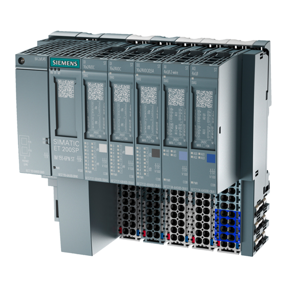
④ ⑩ Wiring diagram BU type ⑤ ⑪ Status LEDs Article number ⑥ LED for supply voltage Figure 2-1 View of the module SIMATIC ET 200SP TM ECC PL ST Technology module TM ECC PL ST (6FE1242-6TM20-0BB1) Manual, 07/2019, A5E43919893B-AA... - Page 14 2.1 Properties Properties The technology module SIMATIC ET 200SP TM ECC PL ST serves to control and monitor the conduction current charging of electric vehicles in accordance with the standard DIN SPEC 70121, Charging mode 4. To this purpose it provides a charging outlet.
- Page 15 Product information for documentation of the ET 200SP Distributed I/O System (https://support.industry.siemens.com/cs/document/73021864?dti=0&lc=en-US). You will find additional information on installation in the ET 200SP distributed I/O system System Manual (http://support.automation.siemens.com/WW/view/en/58649293). Disposal Electric and electronic devices do not belong in household waste. Dispose of the product according to the valid legal regulations at the end of its service life.
- Page 16 Product overview 2.1 Properties Configuration example The charging controller described here is a technology module for SIMATIC ET 200SP. Solutions for S7-1500 CPUs are possible. You have to use TIA Portal as the configuration software. Figure 2-2 Configuration example with one charging outlet...
- Page 17 Product overview 2.1 Properties Updating the firmware Information about carrying out the firmware update is provided in the ET 200SP System Manual. Note Firmware update Note that a firmware update can only be performed in STOP mode. If you initiate the update via TIA Portal, you have to switch the CPU manually to STOP.
-
Page 18: Control Pilot
Product overview 2.2 Control Pilot Control Pilot Control Pilot CP The module generates a Control Pilot signal for the charging outlet. This signal is a square wave signal with 1 kHz frequency and an amplitude of +/-12 V. The duty cycle of the Control Pilot signal is set fixed to 5%. - Page 19 Product overview 2.2 Control Pilot The vehicle indicates its state by applying corresponding resistances. In order to determine the vehicle state the positive component of the PWM signal is acquired as the peak value ) and is read in: Table 2- 1 States and level U State Vehicle...
-
Page 20: Plug Present
Product overview 2.3 Plug Present WARNING To ensure that a fault state (see IEC 61851-23) is sustained after an interruption of the CP signal as required by the standard, you must prevent, on the application level, the unwanted changeover to standby mode after the CP fault. Plug Present Plug Present (relevant for Type 1 plug in accordance with SAE-J1772) The state of the proximity contact (Plug Present;... - Page 21 Product overview 2.3 Plug Present Table 2- 2 Plug Present level Voltage between terminal (7) and (FE) Min [V] Nominal [V] Max [V] At the vehicle when the charging cable is not connect- 4.13 4.46 4.78 At the charging connector when the charging cable is 1.23 1.53 1.82...
-
Page 22: Charge Communication
Product overview 2.4 Charge communication Charge communication The DIN SPEC 70121 describes the digital communication between a direct current charging station and an electric vehicle for regulating the direct current charge in the combined charging system. This standard does not include the functions "Value added Service", "Plug&Charge", "V2G Energy Transfer"... -
Page 23: Session Setup
Product overview 2.4 Charge communication Figure 2-5 Charge phases in accordance with DIN SPEC 70121 Note The parameters are only listed as an example in the following descriptions of the charge phases. For further information, refer to DIN SPEC 70121. 2.4.1 Session Setup The communication starts with the setup of a session (Session Setup). -
Page 24: Service Discovery
Product overview 2.4 Charge communication 2.4.2 Service Discovery After a session has been established successfully the vehicle starts with the search of the offered services. However, DIN SPEC 70121 does not support the search. Therefore no applicable data are exchanged between the vehicle and the charge column in this phase. The vehicle nevertheless sends a ServiceDiscoveryReq message to the charge column. -
Page 25: Cable Check
Product overview 2.4 Charge communication ● Maximum charging voltage ● Maximum charging power during the complete charging process ● Current state of the vehicle (the possible states are described in DIN SPEC 70121) The charge column answers these by sending a ChargeParameterDiscoveryRes message. This includes for example: ●... -
Page 26: Power Delivery
Product overview 2.4 Charge communication This includes for example: ● Current state of the charge column ● Current voltage of the frequency converter This message exchange can be repeated several times until the vehicle accepts the voltage of the frequency converter that is offered. 2.4.8 Power Delivery The Power Delivery phase marks the moment as of which the vehicle is connected to the... -
Page 27: Current Demand
Product overview 2.4 Charge communication 2.4.9 Current Demand After passing through the power delivery phase (the "Ready to charge" status has to be "True" here), the current demand phase takes place. In this phase the charging of the vehicle takes place. To this purpose the vehicle sends the target voltage and the target current to the charge column. -
Page 28: Session Stop
Product overview 2.4 Charge communication 2.4.11 Session Stop After completion of the Welding Detection phase the charging session is completed. Information: If the Welding Detection is not requested by the vehicle, the "Session Stop" is started by the vehicle directly after the PowerDelivery phase. To this purpose the vehicle sends a SessionSetupReq message to the charge column. -
Page 29: Wiring
Wiring Terminal assignment and power supply You have to use a BaseUnit of the BU type B1 or BU type B0 for the SIMATIC ET 200SP TM ECC PL ST. Connect all the required inputs/outputs (CP, PP, DQ T, DQ P) - and in the case of a BaseUnit BU type B1 also a 24 V DC voltage source - to the BaseUnit of the technology module. - Page 30 3.1 Terminal assignment and power supply Information regarding selection of a suitable BaseUnit can be found in the ET 200SP Distributed I/O System System Manual (http://support.automation.siemens.com/WW/view/en/58649293) and in the ET 200SP BaseUnits Manual (http://support.automation.siemens.com/WW/view/en/58532597/133300). Pin assignment of the BaseUnit BU type B1 The table shows the pin assignment of the BaseUnit BU20-P12+A0+4B (6ES7193-6BP20- 0BB1).
- Page 31 Wiring 3.1 Terminal assignment and power supply Pin assignment of the BaseUnit BU type B0 To connect to or use an existing potential group, you must use the following BaseUnit. A new potential group is not created with the BaseUnit BU type B0 (BU20-P12+A4+0B / 6ES7193-6BP20-0BB0).
- Page 32 Wiring 3.1 Terminal assignment and power supply Switching contact DQ P, DQ T ● The digital outputs are protected against short-circuit. ● The digital outputs are equipped for switching inductive loads with a protective diode. Note Connect an external protection element to the relays or contactors to suppress self- inductance when switching off inductive loads.
- Page 33 Note L+- and M insulation at the technology module SIMATIC ET 200SP TM ECC PL ST with help of the BaseUnit type B1. The L+ and M connectors on the BaseUnit of type B1 are galvanically isolated from the neighboring BaseUnits to the left and right.
-
Page 34: Connection Examples
Wiring 3.2 Connection examples Connection examples Block diagrams The circuit diagrams below show the schematic wiring of the technology module with the typical options for use of the feedback input. Figure 3-2 Connection example of the technology module with fast shutdown (when a BU type B1 is used) Note Wiring The CP signal uses a bandwidth of 0 Hz ... -
Page 35: Installation Instruction
Wiring 3.3 Installation instruction Figure 3-3 Connection example of the technology module with fast shutdown (when a BU type B0 is used) Installation instruction Notes on IT security To prevent manipulation of the module, measures must be taken by the owner-operator or person responsible for the system so that unauthorized access is prevented. - Page 36 Wiring 3.3 Installation instruction Technology module TM ECC PL ST (6FE1242-6TM20-0BB1) Manual, 07/2019, A5E43919893B-AA...
-
Page 37: Configuring/Address Space
TM ECC PL ST Hardware Support Package (HSP) If you do not find the technology module SIMATIC ET 200SP TM ECC PL ST in the hardware catalog of the TIA Portal, you have to install the corresponding HSP file (HSP0261 ET200SP ECC PL). -
Page 38: Reaction To Cpu Stop
Breakdowns in communication, such as an interruption of the PROFINET connection, are treated as CPU STOPs. Required I/O address space Address space of the technology module Table 4- 2 Scope of the I/O addresses of the technology module SIMATIC ET 200SP TM ECC PL Inputs Outputs Scope 32 bytes... -
Page 39: Control And Feedback Interface
Configuring/address space 4.5 Control and feedback interface Adjustable parameters Table 4- 4 Configurable parameters and their defaults Parameter Value range Default setting Configuration in RUN Charge standard DIN SPEC 70121 DIN SPEC 70121 Control and feedback interface 4.5.1 Assignment of the control interface The module must be used with the function block DIN_70121. - Page 40 Configuring/address space 4.5 Control and feedback interface Technology module TM ECC PL ST (6FE1242-6TM20-0BB1) Manual, 07/2019, A5E43919893B-AA...
-
Page 41: Programming
Programming General information For operation of the SIMATIC ET 200SP TM ECC PL ST technology module in your application program, you must use the function block "DIN_70121". This function block can be downloaded from the SIEMENS Customer Support (https://support.industry.siemens.com/cs/products?dtp=Download&mfn=ps&pnid=18330&lc= en-DE). It is available in the form of the TIA library "ET200SP TM ECC". There you can find it in the Types/DIN_70121t folder. -
Page 42: Required Memory Of The Function Block Din_70121
Programming 5.3 Required memory of the function block DIN_70121 Required memory of the function block DIN_70121 Required memory The required memory of the DIN_70121 is as follows: Table 5- 1 Required memory of the DIN_70121 function block Charge memory Code work memory Data work memory First instance 1.04 MiB... -
Page 43: Response To Errors
Programming 5.4 Principle of operation of the DIN_70121 function block 5.4.2 Response to errors If an error has occurred, the SW status (out.swState) is initially set to "-1". The frequency converter is then ramped down, if necessary, and the breakers are opened. After the frequency converter is ramped down and the breakers are open, the SW status is set to "-2". -
Page 44: Authentication Phase
Programming 5.4 Principle of operation of the DIN_70121 function block ● Resistance of the Shunt in ohm: in.evseCfg.shuntValueInOhm ● Time monitoring of breakers: in.evseCfg.maxSwitchTimeBreaker ● Feedback signal of the DC breaker: in.values.dcbrk ● Feedback signal of the PreCharge breaker: in.values.prechbrk ●... -
Page 45: Parameter Discovery" Phase
Programming 5.4 Principle of operation of the DIN_70121 function block If no explicit activation is required (e.g. free charging), the parameter can remain permanently set to "2". Note This input is only evaluated during the authentication phase. As soon as the state "1" or "2" is applied, the system changes to the next charging phase. -
Page 46: Checking Safe Isolation From Supply On The Charging Cable (External Voltage Check)
Programming 5.4 Principle of operation of the DIN_70121 function block 5.4.6 Checking safe isolation from supply on the charging cable (External Voltage Check) Before the cable check (insulation measurement) is carried out, a check can optionally be carried out whether the voltage of the charging cable is de-energized. All breakers are open. The voltage of the corresponding voltmeter at the "in.values.extVoltageInVolt"... -
Page 47: Carrying Out The Cable Check
Programming 5.4 Principle of operation of the DIN_70121 function block 5.4.7 Carrying out the Cable Check The isolation of the cable is checked. The cable isolation is faulty if a maximum DC leakage current is exceeded when the maximum voltage of the frequency converter is applied. In this phase the breakers of the vehicle are open. - Page 48 Programming 5.4 Principle of operation of the DIN_70121 function block Corresponding parameters at the function block: ● Maximum charging voltage in Volt of the frequency converter: in.evseCfg.maxVoltageInVolt ● Minimum charging voltage in volt of the frequency converter: in.evseCfg.minVoltageInVolt ● Monitoring time for reaching the target voltage: in.evseCfg.maxTimeRampUpDown ●...
- Page 49 Programming 5.4 Principle of operation of the DIN_70121 function block Figure 5-4 "Cable Check" flow diagram Technology module TM ECC PL ST (6FE1242-6TM20-0BB1) Manual, 07/2019, A5E43919893B-AA...
-
Page 50: Carrying Out The Voltage Equalization Of The Frequency Converter (Precharge)
Programming 5.4 Principle of operation of the DIN_70121 function block 5.4.8 Carrying out the voltage equalization of the frequency converter (PreCharge) In this phase the target voltage and target current for frequency converter are specified by the vehicle. A check is carried out when the voltage required by the vehicle lies within the valid range. ●... -
Page 51: Execution Of The Charge Process (Current Demand)
Programming 5.4 Principle of operation of the DIN_70121 function block 5.4.10 Execution of the charge process (Current Demand) In this phase the frequency converter is controlled by the vehicle with the latest current/voltage specifications. The DIN_70121 function block carries out time monitoring whether the voltage / current / power values lie within the defined limits. -
Page 52: Termination Of The Charging Process
Programming 5.4 Principle of operation of the DIN_70121 function block ● Target voltage in Volt for the frequency converter: out.setpoints.voltageInVolt ● Target current in Ampere for the frequency converter: out.setpoints.currentInAmpere ● Current/voltage control of the frequency converter: out.setpoints.enableCurrentControl ● Measured voltage at the frequency converter in.values.voltageInVolt 5.4.11 Termination of the charging process... -
Page 53: Hardware States
Programming 5.4 Principle of operation of the DIN_70121 function block ● Monitoring time for reaching the target voltage or the target current: in.evseCfg.maxTimeRampUpDown ● Target voltage in Volt for the frequency converter: out.setpoints.voltageInVolt ● Target current in Ampere for the frequency converter: out.setpoints.currentInAmpere ●... - Page 54 Programming 5.4 Principle of operation of the DIN_70121 function block The individual phases as well as the state to be assumed are represented below. ● Initial state (no charging process active): swState = 2 (System in idle state) hwState = 1 (Idle state) ●...
-
Page 55: Din_70121 Parameter
EvseCfg hw_id HW_IO Hardware ID of the technology module SIMATIC ET 200SP TM ECC PL ST for the determination of the offset of the process image of the in- puts/outputs. If an invalid HW ID is entered, a corresponding error bit at the output is set to "True"... -
Page 56: Udt_Charger_Evsecfg
Programming 5.5 DIN_70121 parameter 5.5.2 UDT_Charger_EvseCfg The UDT_Charger_EvseCfg has the following structure: Table 5- 3 List of input parameters for the UDT_Charger_EvseCfg Parameter Data type Description cableCheckCurrentInAm- UInt Current setpoint (in A) during the "Cable check" phase. pere This parameter is relevant for such converters that are required for the start of a minimum current value. - Page 57 Programming 5.5 DIN_70121 parameter maxExtVoltageInVolt UInt The maximum permitted voltage on the cable (external voltage check) before the cable check (see chapter Checking the de-energized state (Page 44)). If exceeded, a corresponding error bit at the output is set to "True" (see section Error messages (Page 66)) maxPowerInkW UInt...
- Page 58 Programming 5.5 DIN_70121 parameter preChargeCurrentInAmpere UInt The maximum allowed charging current (in A) in the "PreCharge" phase. If a minimum current value is required by the frequency converter to start, its high limit is defined here. This current must be less than or equal to the value of "maxCurrentIn- Ampere";...
- Page 59 Programming 5.5 DIN_70121 parameter stopChargingCurrentInAm- UInt If this value is undershot when the charging process is terminated, the DC pere breaker is opened. This current must be less than or equal to the value of "maxCurrentIn- Ampere"; otherwise the error message bit 1 (parameterization error) is set. supportedEnergyTransfer- Word With this parameter you select the energy transfer variants supported by...
-
Page 60: Udt_Charger_Values
Programming 5.5 DIN_70121 parameter 5.5.3 UDT_Charger_Values The UDT_Charger_Values has the following structure: Table 5- 4 List of input parameters to the UDT_Charger_Values Parameter Data type Description authAccepted Byte This parameter indicates whether the charge column is authorized for the charging of a vehicle. It is relevant in the authentication phase. Here the vehicle owner has to, for example, authorize the charging process via RFID. - Page 61 Programming 5.5 DIN_70121 parameter stopCharging Bool Setting this bit to "True" indicates to the vehicle that the charging proce- dure is to be ended. The vehicle decides whether and when the charging process is terminated. voltageInVolt Currently measured voltage of the voltage measuring unit (in V) at the frequency converter output.
-
Page 62: Udt_Charger_Out
Programming 5.5 DIN_70121 parameter 5.5.4 UDT_Charger_Out The UDT_Charger_Out has the following structure: Table 5- 5 List of input parameters to the UDT_Charger_Out Parameter Data type Description UDT_Charger_ Information with regard to the vehicle pilotState USINT Charging state At this output the state is output according to IEC 61851-1. 0: State A1 (100% PWM) •... - Page 63 Programming 5.5 DIN_70121 parameter ppState USINT State of Plug Present (only relevant for Type 1 connector) 0: Vehicle is not connected to the charging station. • 1: Vehicle is connected to the charging station, the button at the con- • nector is pressed 2: Vehicle is connected to the charging station, the button at the con- •...
-
Page 64: Udt_Charger_Ev
Programming 5.5 DIN_70121 parameter 5.5.5 UDT_Charger_Ev The UDT_Charger_Ev has the following structure: Table 5- 6 List of input parameters for the UDT_Charger_Ev Parameter Data type Description Diagnostics UDT_Charger_ Status and diagnostic information with regard to the vehicle. Ev_Diagnostics evccId Array [0..7] of Unique ID of the vehicle. -
Page 65: Udt_Charger_Ev_Diagnostics
Programming 5.5 DIN_70121 parameter 5.5.6 UDT_Charger_Ev_Diagnostics The UDT_Charger_Ev_Diagnose has the following structure: Table 5- 7 List of input parameters to the UDT_Charger_Ev_Diagnose Parameter Data type Description cabinConditioning Bool Information by the vehicle (e.g. heating is on) According to DIN SPEC 70121 evEnergyTransferType Energy transfer type supported by the vehicle The designations of the types are taken directly from the DIN SPEC... -
Page 66: Udt_Charger_Ev_Limits
Programming 5.5 DIN_70121 parameter 5.5.7 UDT_Charger_Ev_Limits The UDT_Charger_Ev_Limits has the following structure: Table 5- 8 List of input parameters for the UDT_Charger_Ev_Limits Parameter Data type Description maxCurrentInAmpere UInt The maximum charging current permitted by the vehicle (in A) maxPowerInkW UInt The maximum charging power permitted by the vehicle (in kW) maxVoltageInVolt UInt... -
Page 67: Udt_Charger_Setpoints
Programming 5.5 DIN_70121 parameter 5.5.8 UDT_Charger_Setpoints The UDT_Charger_Setpoints has the following structure: Table 5- 9 List of input parameters to the UDT_Charger_Setpoints Parameter Data type Description currentInAmpere DInt The current (in A) which is required by the vehicle or the maximum current. Depends on whether the voltage control or current control via the function block is required by the frequency converter. -
Page 68: Error Messages
Programming 5.6 Error messages Error messages The error messages of the function block are described in the following table (refers to the output parameter "out.swError"): Table 5- 10 List of the error messages at the output of the function block Requires Description Remark... - Page 69 Programming 5.6 Error messages Module not ready The module is not ready yet for the next charging • process. The communication module does not report back. • Possible causes of the fault: External 24 V supply of the module is faulty. If possible, the frequency converter is ramped down in a controlled manner.
- Page 70 Programming 5.6 Error messages Current Demand Range errors current, voltage, power The "out.setpoints.voltageInVolt" voltage required by • the vehicle lies outside the valid range. The "out.setpoints.currentInAmpere" current required • by the vehicle lies outside the valid range. The output voltage of the frequency converter •...
- Page 71 Programming 5.6 Error messages The IO modules do not reach the corresponding HW state "out.setpoints.hwState" within the response time defined in "in.evseCfg.maxSwitchTimeHwState". The hardware state "in.values. hwState" has not adjusted to the corresponding HW state "out.setpoints.hwState" within the response time defined in "in.evseCfg.maxSwitchTimeHwState".
- Page 72 Programming 5.6 Error messages Timeout during status change of the The charging protocol provides for a CPU transition from CP from B to C State B to State C at this point. This bit is set if the transi- tion is not made within 1.5 s. Timeout during state change of the CP The charging protocol provides for a CPU transition from from C to B...
-
Page 73: Interrupts/Diagnostic Messages
Interrupts/diagnostic messages State and error displays Front view of the technology module SIMATIC ET 200SP TM ECC PL ST Figure 6-1 Device front with LED displays Meaning of the LED displays The following table shows the meaning of the state and error displays. Details on the error correction can be found in the chapter Diagnostic messages (Page 74). - Page 74 LED DIAG Backplane bus supply of the ET 200SP not OK. Check or switch on the supply voltage of the head station. Ensure that the SIMATIC ET 200SP TM ECC PL ST technology module is correctly plugged into the BaseUnit.
- Page 75 Interrupts/diagnostic messages 6.1 State and error displays Status LEDs LEDs Meaning Enable state Charging outlet (EN) locked by user program. The corresponding VS LED and Status LED F are also off in this case. Charging outlet (EN) activated flashes, S7 communication fault at the charging outlet (EN) •...
-
Page 76: Alarms
Device defect Repairs Repairs by the user or service engineers are not permitted. In case of error please contact Service&Support (https://support.industry.siemens.com/cs/ww/en/sc/3098). WARNING Electric shock hazard May cause death or serious injury Unauthorized opening of the device might place the user in danger or result in substantial damage to property. -
Page 77: Technical Specifications
Technical specifications Technical specifications 6FE1242-6TM20-0BB1 General information Product brand name SIMATIC Product range ET 200SP Product category Technology module Product type designation TM ECC PL ST Product designation Charge controller for conductive charging of electric vehicles Firmware version V1.0 FW update possible •... - Page 78 Technical specifications 7.1 Technical specifications 6FE1242-6TM20-0BB1 Type of digital output Transistor Number of outputs Short-circuit proof Short-circuit protection Yes, electronic / thermal Functions digital outputs, parameterizable PWM output Yes; according to IEC 61851 Max. number • No; 1 kHz Cycle duration parameterizable •...
- Page 79 SIMATIC S7-1500 Dimensions Width 20 mm Height 73 mm Depth 58 mm Weight 32 g Technical specifications related to the BaseUnit See Manual of the ET 200SP BaseUnits (http://support.automation.siemens.com/WW/view/en/58532597/133300). Technology module TM ECC PL ST (6FE1242-6TM20-0BB1) Manual, 07/2019, A5E43919893B-AA...
- Page 80 Technical specifications 7.1 Technical specifications Technology module TM ECC PL ST (6FE1242-6TM20-0BB1) Manual, 07/2019, A5E43919893B-AA...
-
Page 81: Index
Index Device configuration, 36 Address space, 36 Diagnostics alarm, 74 Adjustable parameters, 37, 37 DIN_70121 function block, 39, 53 Authentication phase, 42 Required memory, 40 DIN_70121 parameter, 53 Discovery phase parameters, 43 BaseUnit, 13, 27 DQ P, 30 BaseUnit BU type B0 DQ T, 30 Pin assignment, 29 BaseUnit BU type B1... - Page 82 Index Hardware Support Package (HSP), 35 PowerDelivery phase, 48 HSP download, 35 PP, 18 HSP file, 35, 36 PP function, 19 Pre Charge, 23 Pre Charge phase, 48 Inputs, 12 Product photo, 11 Inputs and outputs, 12 Properties, 12 Installation, 33 Properties of the module, 12 Installation instruction, 33 Protective diode, 30...
- Page 83 Index UDT_Charger_Ev, 62 UDT_Charger_Ev_Diagnose, 63 UDT_Charger_Ev_Limits, 64 UDT_Charger_EvseCfg, 54 UDT_Charger_In, 53 UDT_Charger_Out, 60 UDT_Charger_Setpoints, 65 UDT_Charger_Values, 58 View of the module, 11 Welding Detection, 25, 51 Wiring, 32 Technology module TM ECC PL ST (6FE1242-6TM20-0BB1) Manual, 07/2019, A5E43919893B-AA...
Need help?
Do you have a question about the SIMATIC ET 200SP and is the answer not in the manual?
Questions and answers