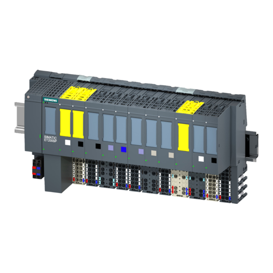
Siemens SIMATIC ET 200SP Operating Instructions Manual

Siemens SIMATIC ET 200SP Operating Instructions Manual

Technology module
Hide thumbs Also See for SIMATIC ET 200SP:
Table of Contents

Advertisement

SIMATIC
ET 200SP
Technology module TM SIWAREX
WP351 HF
Operating Instructions
7MH4138-6BA00-0CU0
01/2020
A5E47521010-AA
Introduction
Product overview
Installing
Connecting
Commissioning
Parameter assignment/
addressing
Operation requiring official
calibration
Service and maintenance
Interrupts/diagnostic
messages
Technical data
Product documentation and
support
Ordering data
1
2
3
4
5
6
7
8
9
10
A
B

Advertisement

Table of Contents
loading

Summary of Contents for Siemens SIMATIC ET 200SP

  • Page 1 Introduction Product overview Installing SIMATIC Connecting ET 200SP Technology module TM SIWAREX Commissioning WP351 HF Parameter assignment/ addressing Operating Instructions Operation requiring official calibration Service and maintenance Interrupts/diagnostic messages Technical data Product documentation and support Ordering data 7MH4138-6BA00-0CU0 01/2020 A5E47521010-AA...
  • Page 2 Note the following: WARNING Siemens products may only be used for the applications described in the catalog and in the relevant technical documentation. If products and components from other manufacturers are used, these must be recommended or approved by Siemens. Proper transport, storage, installation, assembly, commissioning, operation and maintenance are required to ensure that the products operate safely and without any problems.
  • Page 3: Table Of Contents

    View ............................15 Properties..........................16 Version dependencies of the functions ..................16 Installing ..............................17 Basic safety notes ........................17 3.1.1 ATEX/IECx special conditions for use..................17 Mounting on the SIMATIC ET 200SP ..................18 EMC-compliant installation.....................19 3.3.1 Introduction ..........................19 3.3.2 Possible effects of interference ....................19 3.3.3 Coupling mechanisms......................19...
  • Page 4 Table of contents 6.2.2 Calling the function block (FB) ....................41 6.2.3 Executing commands......................44 6.2.4 Cyclic data exchange via "cyclicIoData" ................46 6.2.5 Reading/writing data records ....................48 6.2.6 Design of hardware configuration ..................49 Web server..........................50 6.3.1 Calling the web server......................50 6.3.2 Reading/writing data records ....................51 Operating modes........................53 6.4.1 Weighing steps........................53...
  • Page 5 Table of contents 6.5.29 SecureDisplay version [secureDisplayVersion]..............70 6.5.30 Smallest zoom factor of SecureDisplay (%) [smallestZoomFactorOfSecureDisplay] ....70 DR04 Calibration curve check....................70 DR05 Tare and zero memory....................70 DR06 Configuration of limits ....................71 6.8.1 Reference (limits 1 and 2) [limitReference] ................71 6.8.2 Limit 3 - empty [emptyLimit] ....................71 6.8.3 Switch-on delay limit 3 (empty) (s) [delayTimeForEmptyLimit] ..........72 DR07 Interface parameters....................72...
  • Page 6 Table of contents 6.14.2 Enabling transitions........................85 6.15 DR20 Configuration of set point [setPoint] ................86 6.16 DR21 Configuration of total set point [totalSetPoint]..............86 6.16.1 DR21 Configuration of total set point in DTI................86 6.16.2 DR21 Configuration of total set point GFI ................87 6.17 DR22 Tolerance parameters....................88 6.17.1...
  • Page 7 Table of contents 6.20.5 Weighing start options [startOptions] ..................99 6.20.6 Cycle time for automatic zero setting (s) [cycleTimeAutomaticZeroSetting] ......99 6.20.7 Number of weighings without automatic taring/zero setting [numberOfCyclesWithoutZeroSetting]..................99 6.20.8 Check stop [checkStopAfterStep0 to checkStopAfterStep7]..........99 6.20.9 Automatic discharging [dischargeMode] ................100 6.20.10 Discharge time (s) [dischargeTime] ..................101 6.20.11 Maximum discharge time (s) [dischargeMonitoringTime].............101...
  • Page 8 Table of contents 6.26 DR38 Advanced diagnostic data..................108 6.27 DR39 Statistical data......................108 6.28 DR45 Protocol request......................109 6.29 DR46 Read out protocol content..................109 6.29.1 Overview ..........................109 6.29.2 Oldest protocol ID [oldestLogId]...................109 6.29.3 Youngest protocol ID [latestLogId] ..................109 6.29.4 Selected protocol ID, numerical [selectedLogId]..............109 6.29.5 Protocol string [log] ......................110 6.29.6...
  • Page 9 Table of contents 9.5.2 Meaning of the LEDs......................145 Hardware interrupts......................147 Technical data ............................149 10.1 General information......................149 10.2 Analog load cell interface connection...................150 10.3 Digital inputs DI ........................151 10.4 Digital outputs DQ ........................151 10.5 Counter input CI ........................152 10.6 RS-485 interface ........................152 10.7 Ethernet..........................153 10.8...
  • Page 10 Table of contents Technology module TM SIWAREX WP351 HF Operating Instructions, 01/2020, A5E47521010-AA...
  • Page 11: Introduction

    General information on installation and commissioning of ET 200SP is available in the ET 200SP System Manual. Generally applicable information/SIMATIC manual overview (https://support.industry.siemens.com/cs/ww/en/view/109742709) Use in hazardous area WARNING Use in hazardous area Risk of explosion.
  • Page 12: Security Information

    Siemens’ products and solutions undergo continuous development to make them more secure. Siemens strongly recommends that product updates are applied as soon as they are available and that the latest product versions are used. Use of product versions that are no longer supported, and failure to apply the latest updates may increase customer’s exposure to cyber...
  • Page 13: Open Source Software

    We are liable for the product described, including the open-source software contained in it, pursuant to the conditions applicable to the product. Siemens accepts no liability for the use of the open source software over and above the intended program sequence, or for any faults caused by modifications to the software.
  • Page 14 Introduction 1.4 Open Source Software Technology module TM SIWAREX WP351 HF Operating Instructions, 01/2020, A5E47521010-AA...
  • Page 15: Product Overview

    ⑦ Below: Ethernet Figure 2-1 View of the electronic weighing system See also ET 200SP Distributed I/O System (http://support.automation.siemens.com/WW/view/en/ 58649293) Product information on documentation for the ET 200SP Distributed I/O System (http:// support.automation.siemens.com/WW/view/en/73021864) Technology module TM SIWAREX WP351 HF Operating Instructions, 01/2020, A5E47521010-AA...
  • Page 16: Properties

    Product overview 2.3 Version dependencies of the functions Properties The electronic weighing system has the following properties: ● Technical properties – One channel – Interfaces: Load cell connection with 10 V DC supply voltage; 0.5 µV/e; 3x6000 d ±20,000,000 digit resolution at 1 kHz sampling rate Digital input signals DI.0, DI.1 and DI.2 24 V DC Digital output signals DQ.0, DQ.1 and DQ.2 24 V DC Counter input CI;...
  • Page 17: Installing

    Installing Basic safety notes WARNING Open equipment The devices are "open equipment" according to the standard IEC 61010-2-201 or UL 61010-2-201 / CSA C22.2 No. 61010-2-201. To fulfill requirements for safe operation with regard to mechanical stability, flame retardation, stability, and protection against contact, the following alternative types of installation are specified: ●...
  • Page 18: Mounting On The Simatic Et 200Sp

    Mounting on the SIMATIC ET 200SP Mounting on the SIMATIC ET 200SP Only use the electronic weighing system in conjunction with a SIMATIC ET 200SP distributed I/O system. Install the electronic weighing system in a control cabinet. Observe the information on the protection class and degree of pollution in the section Technical data (Page 149).
  • Page 19: Emc-Compliant Installation

    Installing 3.3 EMC-compliant installation EMC-compliant installation 3.3.1 Introduction Overview The electronic weighing system described here was developed for use in industrial environments and complies with high EMC requirements. Nevertheless, before installing your devices you should prepare an EMC plan and identify and take into consideration possible interference sources.
  • Page 20: Five Basic Rules For Securing Emc

    Installing 3.3 EMC-compliant installation 3.3.4 Five basic rules for securing EMC Observe these five basic rules to secure EMC. Rule 1: Large area grounding contact ● When installing the devices, make sure that the surfaces of inactive metal parts are properly bonded to chassis ground (see following sections).
  • Page 21 Installing 3.3 EMC-compliant installation Rule 5: Homogeneous reference potential ● Create a homogeneous reference potential and ground all electrical equipment. ● Use sufficiently dimensioned equipotential bonding conductors if potential differences exist or are expected between your system components. Equipotential bonding is absolutely mandatory for applications in hazardous areas.
  • Page 22 Installing 3.3 EMC-compliant installation Technology module TM SIWAREX WP351 HF Operating Instructions, 01/2020, A5E47521010-AA...
  • Page 23: Connecting

    Connecting Basic safety notes WARNING Safety extra low voltage The equipment is designed for operation with Safety Extra-Low Voltage (SELV) by a Limited Power Source (LPS). (This does not apply to 100 V...240 V devices.) This means that only SELV / LPS complying with IEC 60950-1 / EN 60950-1 / VDE 0805-1 must be connected to the power supply terminals.
  • Page 24: Connection To Electronic Weighing System

    Information on wiring the BaseUnit, creating the cable shield, etc., can be found in the ET 200SP Distributed I/O System System Manual (http:// support.automation.siemens.com/WW/view/en/58649293) in the section Connecting. Technology module TM SIWAREX WP351 HF Operating Instructions, 01/2020, A5E47521010-AA...
  • Page 25 Connecting 4.2 Connection to electronic weighing system Supply voltage L+/M With a dark BaseUnit, the supply voltage of the left BaseUnit is used. The electronic weighing system monitors whether the supply voltage is connected. Load cell connection In case of 6-wire load cells, the supply voltage is measured over the terminals 1 (SEN+) and 7 (SEN-) and used as reference.
  • Page 26 Connecting 4.2 Connection to electronic weighing system DIAG Bus ASIC RJ45 15 LEDs SEN+ DI.0 SIG+ DI.1 SIG- DI.2 SEN- DQ.0 EXC+ DQ.1 EXC- DQ.2 485+ 485- ① ⑨ Backplane bus interface Color identification label CCxx (optional) ② ⑩ MCU (microcontroller) RS485 device ③...
  • Page 27: Connection Of Analog Load Cells

    Connecting 4.3 Connection of analog load cells Input delay for digital inputs In order to suppress noise you can configure an input delay for the digital inputs. Note If you select the "None" or "0.0001 " option, you must use shielded cables for connection of the digital inputs.
  • Page 28: Connecting Siwarex Jb To The Electronic Weighing System And Load Cell

    Connecting 4.3 Connection of analog load cells 4.3.1 Connecting SIWAREX JB to the electronic weighing system and load cell Procedure 1. Open the cover of the SIWAREX JB. 2. Screw in an M16 x 1.5 cable gland for each load cell. 3.
  • Page 29 Connecting 4.3 Connection of analog load cells SHIELD SENSE- SENSE- EXC- EXC- SIGNAL- SIGNAL- SENSE+ SENSE+ EXC+ EXC+ SIGNAL+ SIGNAL+ Figure 4-3 Cable shield of the signal cable connected to shield terminal The following wire jumpers are set by default: Wire jumper From terminal To terminal...
  • Page 30: Load Cells With Six-Wire System

    Connecting 4.3 Connection of analog load cells 4.3.2.2 Load cells with six-wire system SHIELD SENSE- SENSE- EXC- EXC- SIGNAL- SIGNAL- SENSE+ SENSE+ EXC+ EXC+ SIGNAL+ SIGNAL+ Figure 4-4 Cable shield of load cell cable connected to EMC cable gland SHIELD SENSE- SENSE- EXC-...
  • Page 31: Connecting Cables To Siwarex Jb

    Connecting 4.3 Connection of analog load cells 4.3.3 Connecting cables to SIWAREX JB Requirement You require a screwdriver with a maximum blade width of 3.5 mm. Procedure 1. In EMC cable glands, lay the cable shielding over a large area. Figure 4-6 Place the cable shield in the EMC cable gland 2.
  • Page 32 Connecting 4.3 Connection of analog load cells Technology module TM SIWAREX WP351 HF Operating Instructions, 01/2020, A5E47521010-AA...
  • Page 33: Commissioning

    Commissioning Calibration with calibration weights Introduction As a rule, the characteristic curve can be determined with 2 calibration points. Only determine additional calibration points for non-linear systems. Requirement The scale characteristic curve of the scale consisting of calibration weights and adjustment digits of the electronic weighing system is not known.
  • Page 34 Commissioning 5.1 Calibration with calibration weights 12.Save the calibration data as a backup. 13.Optional: Start the "Check calibration (83)" command. Example The diagram below illustrates the relationship between calibration digits and the calibration weight. Load Comment Load Digits 100 kg load cell (2 mV/V) not loa‐ Approx.
  • Page 35: Automatic Calibration

    Commissioning 5.2 Automatic calibration Load Comment Load Digits 100 kg load cell (2 mV/V) not Approx. 0 loaded Mechanical installation on For 25 kg Approx. 5 000 000 load cell (dead load) Calibration weight 1 placed on‐ For 60 kg Approx.
  • Page 36 Commissioning 5.2 Automatic calibration Requirements Automatic calibration requires the following criteria: ● Correct mechanical installation of the scale without shunt forces ● Scale is empty (only mechanical installation (= dead load) present on the cells) ● Installed load cells are evenly loaded Procedure 1.
  • Page 37: Parameter Assignment/Addressing

    ● Modbus TCP/IP commissioning and parameter assignment – Communication via Modbus (Page 118) Parameter table In addition to the parameter descriptions, the parameter table (https:// support.industry.siemens.com/cs/ww/en/ps/7MH4138-6BA00-0CU0/dl) on the Internet provides information on: ● DR number ● Parameter name ● S7 name ●...
  • Page 38: Tia Portal User Program

    Commissioning the electronic weighing system with TIA Portal Procedure 1. Download the "Ready to use" TIA Portal example project for the technology module TM SIWAREX WP351 HF (https://support.industry.siemens.com/cs/ww/en/ps/17781/dl) from the Internet. The example project must be compatible with your SIMATIC controller.
  • Page 39 Parameter assignment/addressing 6.2 TIA Portal user program 5. In the left-hand tree, navigate to TM SIWAREX WP351 HF. Web server Activate the access for the Web server. HTTPS Function is not supported with FW version 1.0.0. Logon name / Access right / Create up to five different users.
  • Page 40 Parameter assignment/addressing 6.2 TIA Portal user program 6. Enable the desired diagnostic interrupts. Monitoring is always active. When an error is detected, a diagnostic interrupt is only triggered when the corresponding diagnostic interrupt is enabled in the device configuration. 7. Enable the desired hardware interrupts. With the help of the following event types, parameterize the triggering of a hardware interrupt if they are to be used for controlling dosing.
  • Page 41: Calling The Function Block (Fb)

    Parameter assignment/addressing 6.2 TIA Portal user program See also Calling the web server (Page 50) 6.2.2 Calling the function block (FB) Introduction Call the FB WP351 [FB351] separately once for each electronic weighing system cyclically in the user program. For each call of the FB, adapt the input parameters to the electronic weighing system.
  • Page 42 Parameter assignment/addressing 6.2 TIA Portal user program 4. Assign the interface DB to the electronic weighing system for the parameter interface "Interface". HW_ID HW ID of the electronic weighing system Interface Interface DB of the electronic weighing system ERROR "true" = Error RET_VAL The meaning of the error codes can be found in the section: Operating errors (Page 130).
  • Page 43 Parameter assignment/addressing 6.2 TIA Portal user program Example: 2 FBs for 2 electronic weighing systems The following example shows the setup of 2 FBs in 2 networks for 2 electronic weighing systems. Network 1 Interface DB of the flour scale "Instance_flour_scale" "Network 1"...
  • Page 44: Executing Commands

    Parameter assignment/addressing 6.2 TIA Portal user program 6.2.3 Executing commands Introduction Data records (DR) are read or written via specific command codes. There are three command mailboxes within the interface DB for this purpose. The command mailboxes are managed and processed according to priority. When all three command mailboxes are triggered at the same time by the user program, the FB executes them in the following order: Command...
  • Page 45 Parameter assignment/addressing 6.2 TIA Portal user program 3. Set the associated command trigger [trigger] to "true". 4. Evaluate the associated status bits: Command in progress. [inProgress] Command finished without error. [finishedOk] Command rejected or finished with error. [finishedError] [errorCode (Page 133)] [errorAddInfo (Page 137)] You can find a list of data and operating errors in section Operating errors (Page 130).
  • Page 46: Cyclic Data Exchange Via "Cycliciodata

    Parameter assignment/addressing 6.2 TIA Portal user program 6. Write DR03 by entering the command code 4003 for the "code" parameter in the "Command1" command mailbox. 7. Set the associated command trigger "trigger" to "true". 8. Evaluate the associated status bits: Command finished without error.
  • Page 47 Parameter assignment/addressing 6.2 TIA Portal user program Input [inProcessValueReal1 to inProcessValueR‐ I/O process values in Real format according to de‐ eal4] fined parameters in DR07 (Page 72). [inProcessValueDWord1 to inProcessValueD‐ I/O process values in DWord format according to de‐ Word4] fined parameters in DR07 (Page 72).
  • Page 48: Reading/Writing Data Records

    Parameter assignment/addressing 6.2 TIA Portal user program [transitions] Interlock weighing steps [step0 to step7] with the fol‐ lowing bits. Selection code 0 locks weighing step 0. Selection code 1 locks weighing step 1. Selection code 2 locks weighing step 2. Selection code 3 locks weighing step 3.
  • Page 49: Design Of Hardware Configuration

    Parameter assignment/addressing 6.2 TIA Portal user program 1. Switch on service mode by entering the command code 1 for the "code" parameter in the "Command1" command mailbox. 2. Open the interface DB. 3. Read DR07 by entering the command code 2007 for the "code" parameter in the "Command1"...
  • Page 50: Web Server

    Parameter assignment/addressing 6.3 Web server Web server 6.3.1 Calling the web server NOTICE Low degree of protection against unauthorized access If you activate the web server, you reduce protection against unauthorized access to functions and data of the electronic weighing system from outside and via the internal network. ●...
  • Page 51: Reading/Writing Data Records

    Parameter assignment/addressing 6.3 Web server Procedure in case of loss of user data ① 1. Press the pushbutton at the upper left in the enclosure for at least 3 seconds. ② ⇒ LED lights up yellow. 2. Enter the IP address of the electronic weighing system in the Mozilla Firefox or Google Chrome browser within 2 minutes.
  • Page 52 Parameter assignment/addressing 6.3 Web server Example: Reading and writing DR06 1. Read DR06 by selecting "Online > Read data record" in the shortcut menu. Figure 6-6 Reading DR 2. Set the scale parameters for DR06 (Page 71). 3. Write DR06 by selecting "Editor > Write data record" in the shortcut menu. Figure 6-7 Writing DR Technology module TM SIWAREX WP351 HF...
  • Page 53: Operating Modes

    Parameter assignment/addressing 6.4 Operating modes Operating modes 6.4.1 Weighing steps Dosing is always executed in weighing steps. These weighing steps involve the same task in each weighing operating mode and are presented below. The scale status in the interface DB of the "cyclicIoData"...
  • Page 54: Nawi - Non-Automatic Weighing Instrument - Emptying

    Parameter assignment/addressing 6.4 Operating modes 4. Coarse/fine dosing phase starts 5. If configured and necessary, post-dosing occurs (DR22) 6. The electronic weighing system jumps to the "Stopped" state and waits for the "Next" command (1141) by the operator 7. If the "Next" command is issued, the dosed weight is written in the log memory and the final tolerance check is performed.
  • Page 55: Gfi - Gravimetric Filling Instrument

    Parameter assignment/addressing 6.4 Operating modes 6.4.3 GFI - Gravimetric filling instrument In GFI mode, the electronic weighing system also allows a set point to be set, which the dosing functionality of the electronic weighing system then automatically doses. The dosing signals "Coarse flow/Fine flow" can be used to directly control the corresponding dosing elements (e.g.
  • Page 56: Cwi - Catchweighing Instrument/ Cw - Automatic Check Weigher - Emptying

    Parameter assignment/addressing 6.4 Operating modes In contrast to the NAWI weighing operating mode, the logging of the dosed single weight is written automatically to the log memory without an operator intervention. Dosing in continuous operation is possible. In practice, the dosing process may proceed as follows: 1.
  • Page 57: Dti Discontinuous Totalizing Automatic Weighing Instrument

    Parameter assignment/addressing 6.4 Operating modes 6. If configured and necessary, post-dosing occurs (DR 22) (weighing step 3) 7. Dosing result is automatically checked and logged (weighing step 4) 8. Emptying signal is set, if necessary (based on DR 25) (weighing step 5) 9.
  • Page 58: Cw - Automatic Check Weigher

    Parameter assignment/addressing 6.5 DR03 Calibration parameters 6.4.6 CW - Automatic check weigher You set the CW weighing operating mode in data record 3. The CW weighing operating mode enables you to implement a static automatic checkweigher with the electronic weighing system. Test objects are checked for a default set point;...
  • Page 59: Scale Name [Scalename]

    Parameter assignment/addressing 6.5 DR03 Calibration parameters See also Commands (Page 111) 6.5.2 Scale name [scaleName] You can select any name, but it may not exceed 12 characters. You can enter any designation. Note The scale name cannot be changed after official verification. 6.5.3 Weight unit [weightUnit] Sets the weight units.
  • Page 60: Restriction Code [Restrictioncode]

    Parameter assignment/addressing 6.5 DR03 Calibration parameters 6.5.5 Restriction code [restrictionCode] Activates a parameter check in accordance with OIML for operation requiring verification of the scales. Selection code 0 (default) No regulations OIML regulations 6.5.6 Set number of weighing ranges [numberOfWeighingRanges] For legal trade scales, specify whether the scales are operated as single-, dual- or triple-range scales (3x6000d).
  • Page 61: Multi Range / Multi Interval Scale [Multirangemultiintervalscale]

    Parameter assignment/addressing 6.5 DR03 Calibration parameters For scales requiring official calibration, the specification must be greater than the minimum weight for weighing range 2 and is dependent on the number and type of connected load cell(s). Minimum weight weighing range 3 [minWeightWeighingRange3] For scales not requiring official calibration, you can use the default value 0.
  • Page 62: Calibration Weights 0, 1, 2, 3, 4 [Calibrationweight] And Calibration Digits [Calibrationdigit]

    Parameter assignment/addressing 6.5 DR03 Calibration parameters The maximum number of legal-for-trade scale intervals depends on the load cells used (e.g. 6000d with C6 load cells or 3000d with C3 load cells) and may not be exceeded in any of the set ranges in the case of legal-for-trade scales.
  • Page 63: Scale Interval For Weighing Range 1, 2, 3 [Scaleintervalweighingrange]

    Parameter assignment/addressing 6.5 DR03 Calibration parameters 6.5.9 Scale interval for weighing range 1, 2, 3 [scaleIntervalWeighingRange] Can be defined in accordance with the standard EN 45501 (0.0001 to 50). It defines the smallest indicated weight change and conforms to the accuracy of the overall system for scales requiring official calibration.
  • Page 64: Enable Weight Simulation [Weightsimulationenabled]

    Parameter assignment/addressing 6.5 DR03 Calibration parameters The display value is hidden when a subtractive tare is enabled if the gross value exceeds the maximum weighing range by more than 9e. With a subtractive tare device, a maximum of up to 100% of the maximum weighing range (see "Maximum tare load") can be tared.
  • Page 65: Weighing Range Data In Securedisplay [Weighingrangedatainsecuredisplay]

    Parameter assignment/addressing 6.5 DR03 Calibration parameters 6.5.16 Weighing range data in SecureDisplay [weighingRangeDataInSecureDisplay] In legal trade operation, the software version of the HMI device must be recorded so that it can be checked by an official verification officer. 6.5.17 Automatic zero tracking in dosing cycle [automaticZeroTrackingInCycle] The parameter defines whether the zero tracking (if activated) is to be active only outside the automatic dosing cycle (only in weighing step 0) or also inside the dosing cycle.
  • Page 66: Semi-Automatic Zero-Setting Device Limit Negative (% Of Max.) [Semiautomaticzerosettinglimitnegative]

    Parameter assignment/addressing 6.5 DR03 Calibration parameters Example Maximum weighing range= 100 kg Maximum positive zeroing limit = 10% → Up to 10 kg (10% of 100 kg) can be set to zero by the function on power on. 6.5.21 Semi-automatic zero-setting device limit negative (% of max.) [semiAutomaticZeroSettingLimitNegative] Max.
  • Page 67 Parameter assignment/addressing 6.5 DR03 Calibration parameters Stability 1 applies to dosing steps 0, 1, 5, and 6; Stability 2 applies to the remaining dosing steps 2 to 4. Figure 6-8 Stability monitoring Stability weight 1 [stabilityWeight1] The parameter defines the permissible deviation (+/-) by which the weight is allowed to fluctuate within the stability time to detect stability.
  • Page 68: Digital Signal Filters

    Parameter assignment/addressing 6.5 DR03 Calibration parameters Stability weight 2 [stabilityWeight2] The parameter defines the permissible deviation (+/-) at which the weight is allowed to fluctuate within the stability time to detect stability. The input is made in the unit of weight. Stability time 2 (s) [stabilityTime2] Defines the time window in which the current weight value may fluctuate only within the stability weight (+/-) to report stability.
  • Page 69: Operating Mode [Scaleoperatingmode]

    Parameter assignment/addressing 6.5 DR03 Calibration parameters Cut-off frequency low pass filter [cutOffFrequencyLowPassFilter] Defines the limit frequency in Hz of the low pass filter in the range from 0.05 to 200 Hz. Period of dosing filter [dosingFilterPeriod] Defines the period of the dosing filter in seconds. The dosing filter has an additional effect on the weight value during the coarse feed or fine feed.
  • Page 70: Securedisplay Version [Securedisplayversion]

    Parameter assignment/addressing 6.7 DR05 Tare and zero memory 6.5.29 SecureDisplay version [secureDisplayVersion] For applications requiring official calibration, the "SecureDisplay" software is used to display the calibratable weight value. The parameter defines the version of the "SecureDisplay" software that is running in the HMI device. If the version is not entered correctly, a weight value will not be output in "SecureDisplay", and the display stays in the "Start Up"...
  • Page 71: Dr06 Configuration Of Limits

    Parameter assignment/addressing 6.8 DR06 Configuration of limits See also Commands (Page 111) DR06 Configuration of limits 6.8.1 Reference (limits 1 and 2) [limitReference] Defines the weight to which the limits 1 and 2 relate and the interpretation of the ON/OFF values. Selection code Interpretation of the ON/OFF values for limit 1 and lim‐...
  • Page 72: Switch-On Delay Limit 3 (Empty) (S) [Delaytimeforemptylimit]

    Parameter assignment/addressing 6.9 DR07 Interface parameters 6.8.3 Switch-on delay limit 3 (empty) (s) [delayTimeForEmptyLimit] Switch-on delay limit 3 (empty) can be deliberately delayed by a delay time. This is helpful, for example, if the weight is undershot at the moment of opening when the scale is being emptied, which would cause Limit 3 to be fallen below already.
  • Page 73: Filtering Di.0, Di.1, Di.2 And Ci

    Parameter assignment/addressing 6.9 DR07 Interface parameters 6.9.2 Filtering DI.0, DI.1, DI.2 and CI Specify the following values for filtering the digital inputs and the counter input: Selection codes Function Filter DI.0 [filterDI0] Filter DI.1 [filterDI1] Filter DI.2 [filterDI2] Filter CI [filterCI] 0 (default) No filtering 1 …...
  • Page 74: Monitoring Of Digital Outputs [Monitoringofdq]

    Parameter assignment/addressing 6.9 DR07 Interface parameters 6.9.5 Monitoring of digital outputs [monitoringOfDQ] Selection code Function Monitoring inactive Monitoring active 6.9.6 Reaction of digital outputs to a CPU stop / failure [behaviourOfDQOnCPUStopOrFailure] Selection code Function Set substitute values Retain function 6.9.7 Behavior of digital outputs on error [behaviourOfDQOnError] Selection code Function...
  • Page 75: Trace Rate [Tracerate]

    Parameter assignment/addressing 6.9 DR07 Interface parameters 1. Set the "DQ behavior on failure" parameter [behaviourOfDQOnError] to "Set substitute values": Selection code 0. 2. Assign substitute values for the event of an error or stop to the digital outputs (DQ.0, DQ.1 and DQ.2).
  • Page 76: Modbus Tcp Unit Identifier, Port, Swap Options

    Parameter assignment/addressing 6.9 DR07 Interface parameters 6.9.12 Modbus TCP Unit Identifier, port, SWAP options The following options are available for the Modbus TCP/IP interface: Selection code Function [modbusUnitIdentifier1] -1 (default) Unit Identifier is not evaluated Modbus TCP port connection [modbusPort] Defines the port for the Modbus connections.
  • Page 77: I/O Process Values 5 To 8 [Ioprocessvalue5 To Ioprocessvalue8]

    Parameter assignment/addressing 6.9 DR07 Interface parameters I/O process value Selection code Last net process weight Last net weight [lastNetWeight] Totalizer 2 Youngest protocol ID Current dosing step / Number of dosings in continuous mode Load cell impedance Load cell signal voltage Load cell sense voltage Current fine weight Current trailing weight...
  • Page 78: Event Hardware Interrupts 4 To 8 [Hardwareinterrupt4 To Hardwareinterrupt8]

    Parameter assignment/addressing 6.11 DR10 Load cell parameters 6.9.17 Event hardware interrupts 4 to 8 [hardwareInterrupt4 to hardwareInterrupt8] 1. Select the following defined events for up to five additional hardware interrupts [hardwareInterrupt4 to hardwareInterrupt8]: Selection code [hardwareInterrupt4 to hardwar‐ eInterrupt8] 0 ... 79 Scale status bits (see DR30) 100 ...
  • Page 79: Connection Technology [Foursixwiresensor]

    The load cell characteristic value is required to correctly interpret the output voltage from the load cell. When Siemens WL series load cells are used, the exact characteristic value can be read from label on the cell. If the exact characteristic value of the utilized cell(s) is not available, a rounded value can also be specified.
  • Page 80: Power Line Frequency [Powerlinefrequency]

    Parameter assignment/addressing 6.12 DR15 Preset tare 6.11.7 Power line frequency [powerLineFrequency] The parameter defines the line frequency of the power supply grid. A selection between 50 Hz and 60 Hz can be made. By making the correct setting, interferences caused by the power supply grid can be better suppressed.
  • Page 81: Dr16 Configuration Of Weight Simulation

    Parameter assignment/addressing 6.13 DR16 Configuration of weight simulation 3. Write DR15. 4. Activate the current preset tare value with an "Activate preset tare from DR15 (1013)" command. TIA Portal procedure 1. Activate service mode: Command code 1. 2. Read DR07: Command code 2007. 3.
  • Page 82: Simulating Dosing

    Parameter assignment/addressing 6.13 DR16 Configuration of weight simulation 9. Read DR16. 10.in DR16, enter a simulation weight in the measuring range of the scale. 11.Write DR16. 12.Start the simulation using the "Weight simulation ON (3)" command. ⇒ The notice "SIMULATION" is shown on the main display and a status bit is set. ⇒...
  • Page 83: Material Flow, Delay Time And Opening/Closing Time

    Parameter assignment/addressing 6.13 DR16 Configuration of weight simulation Example of emptying time An emptying time of 1 s has the result with enabled simulation (DR03) that emptying at the end of an automatic dosing cycle is simulated within 1 s. Simulation takes place linearly from the dosed weight down to 0 weight units.
  • Page 84: Dr18 Digital Output And Transition Control

    Parameter assignment/addressing 6.14 DR18 Digital output and transition control Extra coarse/coarse/fine/empyting delay time Delay time until the respective material flow is activated or deactivated by switch-on/switch-off. Extra coarse/coarse/fine/empyting opening/closing time Duration until the respective material flow is fully established or terminated. 6.14 DR18 Digital output and transition control 6.14.1...
  • Page 85: Enabling Transitions

    Parameter assignment/addressing 6.14 DR18 Digital output and transition control 5. Deactivate service mode: Command code 2. 6. Control one to three digital outputs in the "cyclicIoData" structure: Selection code 0 activates DQ.0. Selection code 1 activates DQ.1. Selection code 2 activates DQ.2. 6.14.2 Enabling transitions Introduction...
  • Page 86: Dr20 Configuration Of Set Point [Setpoint]

    Parameter assignment/addressing 6.16 DR21 Configuration of total set point [totalSetPoint] 6.15 DR20 Configuration of set point [setPoint] Introduction The set point in "CW - Automatic check weigher" defines the reference weight of an individual dosing to be checked with the defined weight unit (Page 59). Procedure 1.
  • Page 87: Dr21 Configuration Of Total Set Point Gfi

    Parameter assignment/addressing 6.16 DR21 Configuration of total set point [totalSetPoint] Procedure 1. Read DR21. 2. In DR21, define the following parameters with the defined weight unit: – Total set point [totalSetPoint] When you specify a total set point during continuous operation which is smaller than the weighing operations already carried out, continuous operation is stopped following the current weighing operation.
  • Page 88: Dr22 Tolerance Parameters

    Parameter assignment/addressing 6.17 DR22 Tolerance parameters 6.17 DR22 Tolerance parameters 6.17.1 Overview In DR22, you specify the tolerance limits that are to be used in a tolerance check by the electronic weighing system. You can define two tolerance bands around the set point. After the tolerance check, the result of the check is available in the scale status.
  • Page 89: Tolerance Limit Th1 (Weight Unit) [Tolerancelimitth1]

    Parameter assignment/addressing 6.17 DR22 Tolerance parameters 6.17.4 Tolerance limit TH1 (weight unit) [toleranceLimitTh1] This parameter defines the limit of the first tolerance band above the set point. The setting conforms to the selected tolerance reference (percentage or absolute) and must be less than or equal to tolerance limit TH2.
  • Page 90: Pulse Duration For Pulse Post Dosing (S) [Pulseduration]

    Parameter assignment/addressing 6.17 DR22 Tolerance parameters 4: Post-dosing with pulsing. "Fine signal" is switched on in pulsing mode until TL1 is exceeded. The tolerance check is performed again and the weighing cycle is completed with "Dosing completed" as long as a tolerance error is no longer present. The pulse/pause ratio in pulsing mode is defined by the pulse duration (DR22) and the sum of "Stability time 2 + deceleration time before stability 2"...
  • Page 91: Capture Of Weighings Into Statistics [Statisticsdata]

    Parameter assignment/addressing 6.18 DR23 Material parameters 6.17.11 Capture of weighings into statistics [statisticsData] Defines, based on the tolerance evaluation, which dosing results are to be included in the statistics calculation. Selection code Meaning 0 (default) All dosings (with tolerance check) are included following "Dosing completed" in the calculated statistics.
  • Page 92: Trailing Weight Fine [Trailingweightfine]

    Parameter assignment/addressing 6.18 DR23 Material parameters 6.18.3 Trailing weight fine [trailingWeightFine] This parameter defines how much material still flows onto the scale after the fine signal is shut off. Depending on the selected unit reference (DR23), the value must be interpreted as a percentage of the set point (DR20) or as an absolute weight value.
  • Page 93: Coarse Weight [Coarseweight]

    Parameter assignment/addressing 6.18 DR23 Material parameters used by the electronic weighing system can be seen in DR30 (always expressed in DR30 in the weight unit). 6.18.4 Coarse weight [coarseWeight] Relevant with dosing in three dosing steps (extra coarse, coarse and fine). In the case of classic coarse or fine dosing, the coarse weight remains at 0 (default setting).
  • Page 94: Blocking Time Coarse Signal (S) [Blockingtimecoarse]

    Parameter assignment/addressing 6.18 DR23 Material parameters 6.18.8 Blocking time coarse signal (s) [blockingTimeCoarse] This parameter defines a timer that starts when the coarse signal is switched. While the timer is active, the electronic weighing system does not perform a check to determine whether the coarse shut-off point has been reached.
  • Page 95: Minimum Material Flow (Weight/S) [Minimummaterialflowrate]

    Parameter assignment/addressing 6.19 DR24 Controller parameters 6.18.13 Minimum material flow (weight/s) [minimumMaterialFlowRate] The material flow is constantly being measured. The sign of the material flow is always positive for the selected weighing application. Example: You have selected the weighing application "Non-automatic weighing instrument – Removal".
  • Page 96: Control Factor Of Proportional Controller (%) [Controlfactorpcontroller]

    Parameter assignment/addressing 6.19 DR24 Controller parameters Note Blocking time error If blocking time errors occur in two consecutive dosing operations, the shut-off points of the next dosing are reset. The shut-off points are automatically reset to the values currently entered in DR 23.
  • Page 97: Proportional Controller Deadband - Lower Limit [Deadbandpcontrollerminus]

    Parameter assignment/addressing 6.19 DR24 Controller parameters 6.19.7 Proportional controller deadband - lower limit [deadBandPControllerMinus] When proportional controller is activated, a deadband for the controller can be defined. If the achieved final weight of a dosing (with check) is above the lower limit of the deadband, the controller does not correct the shut-off points.
  • Page 98: Adopt Corrected Fine-/Trailing Values To Dr23 Automatically [Adoptcorrectedvalues]

    Parameter assignment/addressing 6.20 DR25 Dosing system parameters 6.19.11 Adopt corrected fine-/trailing values to DR23 automatically [adoptCorrectedValues] At the initial start of a dosing with "Material A", the electronic weighing system calculates the shut-off points for the coarse/fine signal according to settings from DR23 (fine/trailing weight). If the P-controller is active, the fine/trailing weight of "Material A"...
  • Page 99: Maximum Weighing Time (S) [Maximumdosingtime]

    Parameter assignment/addressing 6.20 DR25 Dosing system parameters 6.20.4 Maximum weighing time (s) [maximumDosingTime] This parameter represents a timer that is started at the start of an automatic dosing cycle. If the dosing cycle has not yet finished after expiration of the timer, the electronic weighing system outputs a corresponding technology message that has no further effect on the running dosing cycle.
  • Page 100: Automatic Discharging [Dischargemode]

    Parameter assignment/addressing 6.20 DR25 Dosing system parameters Example: ● The check stop bits are set for weighing steps 1 and 2 and DR25 is transmitted to the electronic weighing system. The "Activate check stop (1122)" command is issued. → The "Check stop follows" bit is set in the AWI Status. ●...
  • Page 101: Discharge Time (S) [Dischargetime]

    Parameter assignment/addressing 6.20 DR25 Dosing system parameters 6.20.10 Discharge time (s) [dischargeTime] The parameter defines a fixed time during which the emptying signal is activated in the emptying step. It applies only when selection code 2 (Emptying according to specified time) is selected as the emptying option in DR25.
  • Page 102: Dosing Signals

    Parameter assignment/addressing 6.21 DR28 Configuration of additional string for protocols 6.20.14 Dosing signals Dosing signals during extra coarse phase [feedOptionsXCoarse] Defines which signals are switched in the "Extra coarse" dosing phase in three-stage dosing (with extra coarse, coarse and fine phase). Selection code Meaning 0 (default)
  • Page 103: Log Single Loadings (Oiml R-107) [Logsingleloadings]

    Parameter assignment/addressing 6.23 DR30 Read out process state 6.21.2 Log single loadings (OIML R-107) [logSingleLoadings] The parameter defines whether single fillings of a load are logged in THW mode in addition to the master totalizer. If single fillings of a load are logged, the single fillings are permanently labeled with the string "delta n", whereby 'n' stands for the number of the current single filling.
  • Page 104: Digits Unfiltered (Linearized) [Unfiltereddigitsnotlin]

    Parameter assignment/addressing 6.23 DR30 Read out process state (https://support.industry.siemens.com/cs/ww/en/ps/7MH4138-6BA00-0CU0/dl) on the Internet. See also section: Introduction (Page 37). Note Reading of DR30 to the PLC via command is not mandatory. In DR07 Interface parameters (Page 72), the user can freely select four process variables that are transmitted automatically via the S7-I/O to the CPU and are available there.
  • Page 105: Refresh Counter [Refreshcounter]

    Parameter assignment/addressing 6.23 DR30 Read out process state 6.23.8 Refresh counter [refreshcounter] The measured values are formed again every millisecond in the electronic weighing system. A counter is incremented by one each time. Once the counter reaches the value 65536, it starts again from zero.
  • Page 106: Gross Process Weight 1 [Grossprocessweight1], Net Process Weight 1

    Parameter assignment/addressing 6.23 DR30 Read out process state 6.23.15 Gross process weight 1 [grossProcessWeight1], Net process weight 1 [netProcessWeight1], Tare process weight [tareProcessWeight] These are the gross, net and tare weights in high-resolution process form. 6.23.16 Gross weight [grossWeight], Net weight [netWeight], Tare weight [tareWeight] These are the gross, net and tare weights after rounding and filtering defined in data record 3.
  • Page 107: Date & Time

    Parameter assignment/addressing 6.24 DR32 Read out error messages 6.23.22 Date & time The Year, Month, Day, Hour, Minute, Second, Millisecond, and Day of the week parameters represent the current date and time set in the electronic weighing system. The electronic weighing system automatically synchronizes the time with the time of the connected CPU.
  • Page 108: Dr34 Weight Indicator

    Parameter assignment/addressing 6.27 DR39 Statistical data 6.25 DR34 Weight indicator DR 34 provides an ASCII string with 16 characters, that can be used as a weight display. The string contains the current gross or net weight after rounding according to DR03, as well as the weight unit.
  • Page 109: Dr45 Protocol Request

    Parameter assignment/addressing 6.29 DR46 Read out protocol content ● No. of weighings per hour ● Number of weighings 6.28 DR45 Protocol request The protocol ID of the log to be displayed in data record 46 is entered here. The protocol ID to be read is also used for the calibratable reading of the log via SecureDisplay. For example, if ID 129 is to be displayed, the value 129 must be entered in DR45 and sent to SIWAREX.
  • Page 110: Protocol String [Log]

    Parameter assignment/addressing 6.29 DR46 Read out protocol content 6.29.5 Protocol string [log] The protocol string contains the following information depending on the scale type: Weighing operating mode DTI - Discontinuous totalizing automatic weighing instruments [Identifier];[Weight value];[Weight unit];[Additional string];[8 spaces] Example: T1;100;kg;Wheat; Designation Data type Length (bytes)
  • Page 111: Dr47 Read Out Logbook Content

    Parameter assignment/addressing 6.31 Commands 6.30 DR47 Read out logbook content Changes to the used software version of SecureDisplay of the legal-for-trade main display [HMI] and changes to the firmware of the electronic weighing system are recorded in the logbook. Scrolling in the logbook is possible using commands 881 to 883. Legal-for-trade reading of the logbook is carried out using the SecureDisplay legal-for-trade main display.
  • Page 112: Commands

    Parameter assignment/addressing 6.31 Commands 6.31.2 Commands Table 6-3 Service commands Com‐ Command Description Write protec‐ mand tion code Service mode ON Turn on service mode Service mode OFF Turn off service mode Weight Simulation on Requirement: You have generally released simulation mode in DR03. Turn on test mode.
  • Page 113 Parameter assignment/addressing 6.31 Commands Com‐ Command Description Write protec‐ mand tion code Automatic calibration Calculating the scale characteristic curve based on the load cell pa‐ rameters from DR10. The calculated characteristic curve is entered directly in DR03 and DR04, and thus activated immediately after exe‐ cuting the command.
  • Page 114 Parameter assignment/addressing 6.31 Commands Table 6-6 Totalization commands Com‐ Command Description Write pro‐ mand tection code Delete total 1 Deletes total 1 in DR30 (not possible for THW in OIML mode) Delete total 2 Deletes total 2 in DR30 Log and delete total 1 Logs total 1 in alibi memory and then deletes it (THW mode) Table 6-7 Display changeover for DR34 and SecureDisplay...
  • Page 115 Parameter assignment/addressing 6.31 Commands Com‐ Command Description Write pro‐ mand tection code SecureDisplay position 1 Shows the SecureDisplay on the HMI in position 1 (see DisplayCa‐ li.xml). SecureDisplay position 2 Shows the SecureDisplay on the HMI in position 2 (see DisplayCa‐ li.xml).
  • Page 116 Parameter assignment/addressing 6.31 Commands Table 6-9 Weighing commands Com‐ Command Description Write pro‐ mand tection code 1101 Start single weighing Starts an individual dosing cycle. 1103 Start continuous mode Starts n dosing cycles in continuous succession Continuous operation ends automatically if a total set point (DR21) was specified and reached or alternatively using the "Stop continuous mode (1123)"...
  • Page 117 Parameter assignment/addressing 6.31 Commands Com‐ Command Description Write pro‐ mand tection code 1128 Rest emptying The command can only be accepted if an emptying option (emptying based on Limit 3 or time) is configured in DR25. Within a weighing cycle, the command causes the coarse and fine signal to be shut off immediately and the scale jumps directly to the emptying step.
  • Page 118: Command Groups Of The Electronic Weighing System

    You can exchange the current process values and parameters via Ethernet with Modbus TCP/ IP. You can find the Modbus address in the parameter table (https:// support.industry.siemens.com/cs/ww/en/ps/7MH4138-6BA00-0CU0/dl) on the Internet. See also section: Introduction (Page 37). The following chapters describe the specifications for handling communication. You can perform the following functions: ●...
  • Page 119: Principle Of Data Transmission

    Parameter assignment/addressing 6.32 Communication via Modbus 6.32.2 Principle of data transmission This description is valid for communication via Modbus TCP/IP. The standardized Modbus protocol is used for communication. The connected communication partner always has the master function, while the electronic weighing system is always the slave.
  • Page 120: Reading Registers

    If you wish to read the registers from the data records DR03 to DR29, you must first export these as a complete data record to the internal output buffer. All Modbus registers of the individual parameters can be found in section → Parameter table (https://support.industry.siemens.com/cs/ww/en/ps/17781/dl). Example A parameter is to be read from DR03.
  • Page 121: Writing Registers

    You can find all other command codes in section → Commands (Page 111). A document for working with the electronic weighing system and Modbus is also available online →Modbus communication of WP231 (https://support.industry.siemens.com/cs/ww/en/ view/77913998). Technology module TM SIWAREX WP351 HF...
  • Page 122 Parameter assignment/addressing 6.32 Communication via Modbus Technology module TM SIWAREX WP351 HF Operating Instructions, 01/2020, A5E47521010-AA...
  • Page 123: Operation Requiring Official Calibration

    ● You have printed the ID labels for the scales and the calibratable main display on the labeling foil. Templates ID labels (https://support.industry.siemens.com/cs/ww/en/view/109764526) ● You have commissioned the scales. ● You have installed SIMATIC HMI or the computer so that it is visible from the scales.
  • Page 124 Use the SIWAREX SecureDisplay software to convert your SIMATIC HMI or computer into the calibratable main display of the scales. SIWAREX SecureDisplay software and description (https:// support.industry.siemens.com/cs/ww/de/view/109477602) 2. Integrate the WP351 example project in your SIMATIC HMI project. - Or - Create your own visualization.
  • Page 125: Checking Parameters Relevant To The Calibration

    Operation requiring official calibration 7.2 Checking parameters relevant to the calibration 9. Place the unlock protection on the BaseUnit in such a way that the top end of the unlock protection is placed in the housing of the electronic weighing system. ①...
  • Page 126 Operation requiring official calibration 7.2 Checking parameters relevant to the calibration Procedure 1. Check the following parameters in the legal-for-trade main display in the "legal-for-trade verification" view. – The software ID of the SIWAREX SecureDisplay (DisplayCali.exe function) corresponds to the requirements in the SIWAREX SecureDisplay test certificate (EC). –...
  • Page 127: Service And Maintenance

    Further information about devices containing batteries can be found at: Information on battery/product return (WEEE) (https:// support.industry.siemens.com/cs/document/109479891/) Note Special disposal required The device includes components that require special disposal. ● Dispose of the device properly and environmentally through a local waste disposal contractor.
  • Page 128 Service and maintenance 8.1 Disposal Technology module TM SIWAREX WP351 HF Operating Instructions, 01/2020, A5E47521010-AA...
  • Page 129: Interrupts/Diagnostic Messages

    Interrupts/diagnostic messages Message and error types Three types are distinguished: Operating errors Operating errors can occur spontaneously at any time due to an unforeseen event. They include internal and external hardware problems which can occur spontaneously during weighing, e.g. wire break of the load cell cable. Data and operating errors Data and command errors arise always as response to a command or a data record transfer.
  • Page 130: Evaluating Errors/Messages Using The Fb

    Interrupts/diagnostic messages 9.4 Operating errors Evaluating errors/messages using the FB In the event of an error, the FB of WP351 reads out DR32 automatically. Data/operating errors and technology messages are reported for 3 s. Operating errors remain permanently until the cause is resolved.
  • Page 131: Technology Messages

    Interrupts/diagnostic messages 9.4 Operating errors Operating errors Error Description and remedy code 1107 SecureDisplay failure 1107 The calibratable main display (SIWAREX SecureDisplay on SIMATIC HMI) no longer communicates with the electronic weighing system ● Check the wiring between the SIMATIC HMI and the CPU or the electronic weighing system and the SIMATIC controller.
  • Page 132 Interrupts/diagnostic messages 9.4 Operating errors Technology messages Error code Description and remedy 2105 Set point too small 2105 The currently specified set point is too small. Remedy: Check the set point setting in DR20. 2106 Error fine weight 2106 Trailing weight (DR23) and single set point (DR20) are incompati‐ ble.
  • Page 133: Data And Command Errors

    Interrupts/diagnostic messages 9.4 Operating errors Technology messages Error code Description and remedy 2122 Inhibition time "extra coarse" error 2122 Inhibition time extra course. After expiration of the inhibition time extra coarse, the extra coarse shut-off point was already exceeded 2123 Extra coarse shut-off point already 2123 The extra coarse shut-off point is already exceeded before switch‐...
  • Page 134 Interrupts/diagnostic messages 9.4 Operating errors Data and command errors Error code Add info Description [errorCode] [errorAd‐ dInfo] 9511 Write protection enabled 9520 Increment between calibration digits too small 9521 Sequence of calibration points is not correct 9522 Calibration not yet complete 9523 Calibration digits out of valid range 9524...
  • Page 135 Interrupts/diagnostic messages 9.4 Operating errors Data and command errors Error code Add info Description [errorCode] [errorAd‐ dInfo] 9500 Fault present 9501 No stability 9502 Waiting for stability 9511 Write protection enabled 9532 Current weight is out of defined weighing range 9533 Total too small 9550...
  • Page 136 Interrupts/diagnostic messages 9.4 Operating errors Data and command errors Error code Add info Description [errorCode] [errorAd‐ dInfo] 9510 Service mode not active 9530 Weight is outside the permissible tare weight range 9531 Weight is outside the permissible zero setting range 7055 Parameter error DR06 7055 Additional information indicates an implausible parameter in DR06 Parame‐...
  • Page 137: Add Info [Erroraddinfo] For Dr03

    Interrupts/diagnostic messages 9.4 Operating errors Data and command errors Error code Add info Description [errorCode] [errorAd‐ dInfo] 9192 Coarse dribbling is not plausible 9183 Filter depth material flow is too high 9182 Minimum material flow is negative 7063 Parameter error DR 24 7063 Additional information indicates an implausible parameter in DR 24 Parame‐...
  • Page 138 Interrupts/diagnostic messages 9.4 Operating errors Parameter Add info [errorAddInfo] Minimum weight weighing range 2 Maximum weight weighing range 2 Minimum weight weighing range 3 Maximum weight weighing range 3 Calibration weight 0 Calibration weight 1 Calibration weight 2 Calibration weight 3 Calibration weight 4 Calibration digits 0 (measured) Calibration digits 1 (measured)
  • Page 139: Add Info [Erroraddinfo] For Dr05 And Dr06

    Interrupts/diagnostic messages 9.4 Operating errors Parameter Add info [errorAddInfo] Filter 2 period (s) Characteristic low pass filter Ordinal number low pass filter Cut-off frequency low pass filter Operating mode Totalization scale interval dt Minimum totalized load SecureDisplay interface Stringheader FW-Version SecureDisplay Version SecureDisplay Smallest zoom factor of SecureDisplay (%) Period of dosing filter...
  • Page 140 Interrupts/diagnostic messages 9.4 Operating errors Parameter Add info [errorAddInfo] Assignment digital input DI.2 Assignment CI Filter DI.0 (0.1ms) Filter DI.1 (0.1ms) Filter DI.2 (0.1ms) Filter CI (0.1ms) Assignment digital output DQ.0 Assignment digital output DQ.1 Assignment digital output DQ.2 DQ monitoring DQ substitute values DQ.0 substitute value on error / CPU-Stop DQ.1 substitute value on error / CPU-Stop...
  • Page 141: Add Info [Erroraddinfo] For Dr10

    Interrupts/diagnostic messages 9.4 Operating errors Parameter Add info [errorAddInfo] Modbus TCP Port number connection 2 Modbus settings connection 2 Enable connection Byte swap for text fields Byte swap for 16 bit tags Byte swap for 32 bit tags (1 # 2, 3 # 4) Word swap for 32 bit tags (1, 2 # 3, 4) I/O process value 1 I/O process value 2...
  • Page 142: Add Info [Erroraddinfo] For Dr20 To Dr24

    Interrupts/diagnostic messages 9.4 Operating errors Parameter Add info [errorAddInfo] Stringheader load cell order number 1028 Load cell order number 1029 9.4.8 Add info [errorAddInfo] for DR20 to DR24 Table 9-7 Add info [errorAddInfo] for DR20 to DR24 Parameter Add info [errorAddInfo] Set point 2001 Total set point...
  • Page 143: Add Info [Erroraddinfo] For Dr25 And Dr28

    Interrupts/diagnostic messages 9.4 Operating errors Parameter Add info [errorAddInfo] Bitfield: Controller settings 2408 Controller behavior in case of exceeding max. control access 2409 Intervention of fine time controller 2410 Set point fine time controller (s) 2430 Adopt corrected fine-/trailing values to DR23 automatically 2431 Max.
  • Page 144: Diagnostic Messages

    Interrupts/diagnostic messages 9.5 Diagnostic messages Diagnostic messages 9.5.1 Error codes and corrective measures Diagnostic results are displayed as plain text in STEP 7 (TIA Portal) via the online and diagnostic message view. Evaluate the error codes by means of the user program. Error code Message Cause/Remedy No supply voltage L+...
  • Page 145: Meaning Of The Leds

    Interrupts/diagnostic messages 9.5 Diagnostic messages and in function manual Diagnostics (https://support.industry.siemens.com/cs/ww/en/view/ 59192926), section "System diagnostics in user program". If the module is being operated as a distributed module in an ET 200SP system with PROFIBUS DP, you have the option of reading out diagnostic data with the RDREC or RD_REC instruction using data record 0 and 1.
  • Page 146 Interrupts/diagnostic messages 9.5 Diagnostic messages LEDs Meaning Solution ③ DI.2 Green/of Input is not active Green/o Input is active ④ DQ.0 Green/of Output is not active Green/o Output is active Green/ Fault at DQ.0, 1 or 2 ● Check the wiring of the outputs. flashing ⑤...
  • Page 147: Hardware Interrupts

    Interrupts/diagnostic messages 9.6 Hardware interrupts LEDs Meaning Solution ⑬ Yellow/o Weight within the weighing range Yellow/o Weight outside of the weigh‐ ing range ⑭ Green/ Stability 1 is not available flashing Green/o Stability 1 is available ⑮ Green/of No automatic weighing cycle is active Green/o Automatic weighing cycle is...
  • Page 148 Interrupts/diagnostic messages 9.6 Hardware interrupts What is a hardware interrupt? In accordance with the parameters assigned, the electronic weighing system triggers a hardware interrupt when certain events or states occur. When a hardware interrupt occurs, the CPU interrupts execution of the user program and processes the associated hardware interrupt organization block (OB).
  • Page 149: Technical Data

    Technical data 10.1 General information Article number 7MH4138-6BA00-0CU0 General information Product type designation Technology module TM SIWAREX WP351 HF Firmware version V1.0 ● FW update possible usable BaseUnits BU type U0 Reliability Mean Time Between Failure MTBF 60 years @T = 40 °C (continuous operation) Product function I&M data...
  • Page 150: Analog Load Cell Interface Connection

    Technical data 10.2 Analog load cell interface connection 10.2 Analog load cell interface connection Article number 7MH4138-6BA00-0CU0 Analog load cell interface connection Error limit according to DIN 1319-1 at 20 °C +/-10 K ≤ 0.002% v.E. Relative accuracy (absolute accuracy can only be achieved with local calibration with calibration standards) Measuring accuracy in ac‐...
  • Page 151: Digital Inputs Di

    Technical data 10.4 Digital outputs DQ 10.3 Digital inputs DI The digital inputs are non-isolated with the ground of the electronic weighing system supply voltage 24 V. Article number 7MH4138-6BA00-0CU0 Digital inputs Number of inputs Input voltage 24 V ● Rated value (DC) 30 V DC ●...
  • Page 152: Counter Input Ci

    Technical data 10.6 RS-485 interface Article number 7MH4138-6BA00-0CU0 Output delay with resistive load typ. 16 µs turn-on typ. 29 µs turn-off RDSON < 0.2 Ω Electrical isolation 500 V AC Cable length 500 m ● Shielded, max. 150 m ● Unshielded, max. 10.5 Counter input CI The counter input is isolated from L+ / M of the 24 V supply voltage of the electronic weighing...
  • Page 153: Ethernet

    Technical data 10.9 Mechanical requirements and data Article number 7MH4138-6BA00-0CU0 Stop bits 1 or 2 Terminating resistors (permanently installed) 390 Ω / 220 Ω / 390 Ω Electrical isolation 500 V AC Cable length ≤ 115 Kbps max. 1,000 m (fieldbus cable 2-wire, shielded, e.g.
  • Page 154: Electrical, Emc And Climatic Requirements

    Technical data 10.10 Electrical, EMC and climatic requirements Article number 7MH4138-6BA00-0CU0 5 ... 8.4 Hz: 3.5 mm out. ● IEC 61131-2:2017 8.4 to 150 Hz: 9.8 m/s (= 1 G) ● IEC 60068-2-6:2007 ● Test Fc Shock load during operation ●...
  • Page 155 Technical data 10.10 Electrical, EMC and climatic requirements Article number 7MH4138-6BA00-0CU0 Air gaps and IEC 61131-2:2017 Overvoltage category II creepage distan‐ IEC 61010-1:2016 Pollution degree 2 UL 61010-2-201:2018 CSA C22.2, No. 142 Isolation stability IEC 61131-2:2017 Ethernet port: CSA C22.2, No. 142 1 500 V AC UL 61010-2-201:2018 Other electrical circuits:...
  • Page 156 Technical data 10.10 Electrical, EMC and climatic requirements Article number 7MH4138-6BA00-0CU0 Interference im‐ munity in indus‐ trial area in ac‐ cordance with EN 61000-6-2 Burst pulses on EN 61000-4-4:2004 ±1.0 kV / ±2.0 kV 5/50 ns/5 kHz power supply ca‐ EN 45501:2015 bles OIML R 76:2006...
  • Page 157: Ambient Conditions

    With a total current ≥ 0.6 A of the digital outputs DQ, reduce the ambient temperature by -1 °C per 100 mA. The maximum permissible total current is 1.5 A. 10.12 Certificates and approvals The approvals are available online at Certificates (https://support.industry.siemens.com/cs/ww/ en/ps/7MH4138-6BA00-0CU0/cert). When using the electronic weighing system in a hazardous area, observe the ATEX/IECx special conditions for use (Page 17). Note The current approvals for your device can be found on the nameplate.
  • Page 158 Technical data 10.12 Certificates and approvals Symbol Standard Marking → CE approval Explosion protection in accordance with c- ANSI / ISA 12.12.01 UL-us (USA/Canada) CSA C22.2 No. 213-M1987 CL. I, Div. 2 GP.A.B.C.D T.. T4 CL. I, Zone 2, GP. IIC, T.. T4 Report no.: E239877 Explosion protection in accordance with II 3 G Ex ec IIC T..
  • Page 159: Product Documentation And Support

    Additional information on our technical support can be found at Technical Support (http:// www.siemens.com/automation/csi/service). Service & support on the Internet In addition to our technical support, Siemens offers comprehensive online services at Service & Support (http://www.siemens.com/automation/serviceandsupport). Technology module TM SIWAREX WP351 HF Operating Instructions, 01/2020, A5E47521010-AA...
  • Page 160 Product documentation and support A.2 Technical support Contact If you have further questions about the device, contact your local Siemens representative at Personal Contact (http://www.automation.siemens.com/partner). To find the contact for your product, go to "all products and branches" and select "Products &...
  • Page 161: Ordering Data

    Product Information for the documentation of the ET 200SP Distributed I/O System (http://support.automation.siemens.com/WW/view/en/73021864). Information regarding selection of the suitable BaseUnit can be found in the ET 200SP Distributed I/O System (http://support.automation.siemens.com/WW/view/en/58649293) system manual and in the ET 200SP BaseUnits (http:// support.automation.siemens.com/WW/view/en/58532597/133300) manual.
  • Page 162 Ordering data B.1 Accessories Technology module TM SIWAREX WP351 HF Operating Instructions, 01/2020, A5E47521010-AA...
  • Page 163: Index

    Index Access, 15, 27, 37, 39, 50, 51, 112, 118, 147 Data record, 44, 48, 51, (DR) activateModbusConnection1, 75 ~ read, 48, 51 activateModbusConnection2, 75 ~ write, 48, 51 Acyclic data exchange, 48, 51 ~read, 44 addAdditionalText, 102 ~write, 44 addInfo, 48 Data type, 37 additionalText, 102...
  • Page 164 Index Gravimetric filling instrument, (GFI) NAWI - Non automatic weighing instrument, 53, 54 Hardware configuration, 49 ~ fill, 53 Hardware interrupts, 40 ~ remove, 54 Hardware Support Package, 49 Non-automatic weighing instrument, (NAWI) Hotline, (Refer to Support request) numberOfWeighingRanges, 60 HTTPS, 39 HW_ID, 41 Operating errors, 130, 131...
  • Page 165 Index SIWATOOL, (Web server) Stability, 55, 58, 67, 90, 131, 132, 133, 134, 135 stabilityTime1, 67 stabilityTime2, 68 stabilityWeight1, 67 stabilityWeight2, 68 Standstill, (Stability) Standstill time, (Stability time) Status information, 37, 104 STEP 7 (TIA Portal), 37 substituteValueDQ0, 75 substituteValueDQ1, 75 substituteValueDQ2, 75 substituteValueDQ3, 75 Support, 159...
  • Page 166 Index Technology module TM SIWAREX WP351 HF Operating Instructions, 01/2020, A5E47521010-AA...

This manual is also suitable for:

Tm siwarex wp351 hf

Table of Contents