
Subscribe to Our Youtube Channel
Related Manuals for Quanmax QBOX-100P Series


Summary of Contents for Quanmax QBOX-100P Series
- Page 1 USER GUIDE QBOX-100P Series Doc. User Guide, Rev. 1.0 Doc. ID: [To be Determined] // 1...
- Page 2 QBOX-100P Series - User Guide, Rev. 1.0 This page has been intentionally left blank // 2...
- Page 3 QBOX-100P Series - User Guide, Rev. 1.0 QBOX-100P SERIES - USER GUIDE Disclaimer We would like to point out that the information contained in this user guide may be subject to alteration, particularly as a result of the constant upgrading of our products. This document does not entail any guarantee on the part of us with respect to technical processes described in the user guide or any product characteristics set out in the user guide.
- Page 4 QBOX-100P Series - User Guide, Rev. 1.0 High Risk Applications Hazard Notice THIS DEVICE AND ASSOCIATED SOFTWARE ARE NOT DESIGNED, MANUFACTURED OR INTENDED FOR USE OR RESALE FOR THE OPERATION OF NUCLEAR FACILITIES, THE NAVIGATION, CONTROL OR COMMUNICATION SYSTEMS FOR AIRCRAFT OR OTHER TRANSPORTATION, AIR TRAFFIC CONTROL, LIFE...
- Page 5 QBOX-100P Series - User Guide, Rev. 1.0 Revision History Revision Brief Description of Changes Date of Issue Initial Issue 2019-Jul-17 Terms and Conditions We warrant products in accordance with defined regional warranty periods. For more information about warranty compliance and conformity, and the warranty period in your region, refer to our website or contact us.
-
Page 6: Symbols
QBOX-100P Series - User Guide, Rev. 1.0 Symbols The following symbols may be used in this user guide DANGER indicates a hazardous situation which, if not avoided, will result in death or serious injury. WARNING indicates a hazardous situation which, if not avoided, could result in death or serious injury. -
Page 7: For Your Safety
QBOX-100P Series – User Guide, Rev. 1.0 For Your Safety Your new ordered product was developed and tested carefully to provide all features necessary to ensure its compliance with electrical safety requirements. It was also designed for a long fault-free life. However, the life expectancy of your product can be drastically reduced by improper treatment during unpacking and installation. -
Page 8: Lithium Battery Precautions
QBOX-100P Series - User Guide, Rev. 1.0 Lithium Battery Precautions If your product is equipped with a lithium battery, take the following precautions when replacing the battery. Danger of explosion if the battery is replaced incorrectly. Replace only with same or equivalent battery type recommended by the manufacturer. -
Page 9: Table Of Contents
4.3. Internal View ......................................23 4.3.1. DDR3L SO-DIMM Memory Socket ..............................24 4.3.2. SATA Power / Data Connector ................................ 24 4.3.3. M.2 Socket ......................................24 Accessing Internal Components ..............................25 5.1. Opening and Closing the QBOX-100P Series ........................... 26 // 9... -
Page 10: List Of Tables
QBOX-100P Series - User Guide, Rev. 1.0 5.1.1. Installing an HDD / SSD ..................................27 5.1.2. Installing an M.2 expansion card ..............................28 Thermal Considerations ................................. 29 6.1. Available Processors....................................29 6.2. Convection Cooling ....................................29 6.3. System Clearance ....................................29 6.4. -
Page 11: List Of Figures
Figure 3: Internal view (without cover) ..............................23 Figure 4: Internal view (bottom side of the baseboard) ........................23 Figure 5: Descrewing the access cover of the QBOX-100P Series ....................26 Figure 6: Descrewing the baseboard of the QBOX-100P Series ...................... 26 Figure 7: Installing an HDD / SSD ................................ -
Page 12: 1/ General Safety Instructions For It Equipment
QBOX-100P Series - User Guide, Rev. 1.0 1/ General Safety Instructions for IT Equipment Please read this chapter carefully and take careful note of the instructions, which have been compiled for your safety and to ensure to apply in accordance with intended regulations. If the following general safety instructions are not observed, it could lead to injuries to the operator and/or damage of the product;... - Page 13 QBOX-100P Series - User Guide, Rev. 1.0 Additional safety instructions for DC power supply circuits To guarantee safe operation of devices with DC power supply voltages larger than 60 volts DC or a power consumption larger than 240 VA, please observe that: ...
-
Page 14: Electrostatic Discharge (Esd)
QBOX-100P Series - User Guide, Rev. 1.0 1.1. Electrostatic Discharge (ESD) A sudden discharge of electrostatic electricity can destroy static-sensitive devices or micro-circuitry. Therefore proper packaging and grounding techniques are necessary precautions to prevent damage. Always take the following precautions: Transport boards in ESD-safe containers such as boxes or bags. - Page 15 QBOX-100P Series - User Guide, Rev. 1.0 A battery subjected to extremely low air pressure that may result in an explosion or the leakage of flammable liquid or gas Do not dispose of lithium batteries in general trash collection. Dispose of the battery according to the local regulations dealing with the disposal of these special materials, (e.g.
-
Page 16: 2/ Electromagnetic Compatibility
QBOX-100P Series - User Guide, Rev. 1.0 2/ Electromagnetic Compatibility For detailed information refer to section 10.3 “CE Directives and Standards”. 2.1. Electromagnetic Compatibility (EU) This product has been designed for low level of radiated emission for residential, commercial and light industrial environments and high immunity level for industrial environmental. -
Page 17: 3/ Shipment And Unpacking
If you notice any shipping damage or inconsistencies between the contents and your order, please contact us for help and information. 3.2. Scope of Delivery 3.2.1. Standard 1x QBOX-100P Series (corresponding to the ordered system configuration) 1x Power adapter (Phoenix power plug terminal attached) 1x Power cord (plug type depending on country) ... -
Page 18: 4/ System Overview
QBOX-100P Series - User Guide, Rev. 1.0 4/ System Overview The QBOX-100P Series is an embedded system enclosed within a compact chassis, offering an optimal ration of computational power and form factor. It can be optionally factory-equipped with an M.2 Wi-Fi, Bluetooth or combo card for two antennas. Users may choose the implementation of a 2.5"... -
Page 19: System Expansion Capabilities
4.1. System Expansion Capabilities 4.1.1. System Expansion via SATA Interface The QBOX-100P Series comes with a 15+7-pin SATA power / data connector. Users can expand the system with a 2.5" SATA HDD / SSD drive. 4.1.2. System Expansion via M.2 Card Interface The baseboard comes with an onboard M.2 interface connector with Key A Type 2232 support. -
Page 20: Front I/O Panel
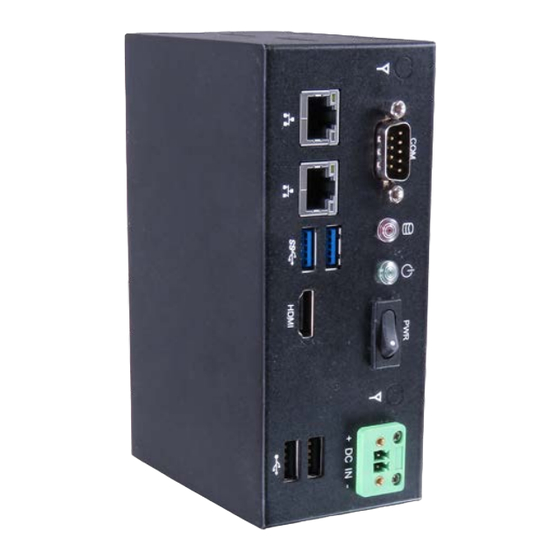
QBOX-100P Series - User Guide, Rev. 1.0 4.2. Front I/O Panel Figure 1: Front I/O Panel DC-In (see Chapter 4.2.1) Power Switch (See Chapter 4.2.2) Power LED (see Chapter 4.2.3) Storage LED (see Chapter 4.2.4) HDMI (see Chapter 4.2.5) GbE (see Chapter 4.2.6) USB 3.0 (see Chapter 4.2.7) -
Page 21: Power Switch
Steady Green - Link is up, no activity Off - 10 Mbit/s link established 4.2.7. USB 3.0 The QBOX-100P Series provides two USB 3.0 / 2.0 interfaces. These connectors allow connection of USB 3.0 or USB 2.0 compatible devices to the system. // 21... -
Page 22: Usb 2.0
RS232/422/485 serial communication which can be configured via BIOS setup. 4.2.10. Wi-Fi Antenna Port The QBOX-100P Series reserves two covered cutouts for the Reverse (RP) SMA connectors of the WLAN antennas (M.2 WLAN card with 2 antennas is an option). -
Page 23: Internal View
QBOX-100P Series - User Guide, Rev. 1.0 4.3. Internal View Figure 3: Internal view (without cover) 15+7-pin SATA Power / Data Connector (see Chapter 4.3.2) Figure 4: Internal view (bottom side of the baseboard) DDR3L SO-DIMM Memory Socket (DIMM1, see Chapter 4.3.1) M.2 Key A Socket (SLOT1, see Chapter 4.3.3) -
Page 24: Ddr3L So-Dimm Memory Socket
HDD power output wafer for installing a 2.5" HDD / SSD. The HDD / SSD is intended to be fixed on the underside of the access cover. 4.3.3. M.2 Socket The QBOX-100P Series reserves one M.2 Key A socket, allowing the expansion with a Type 22x32 Wi-Fi, Bluetooth or combo card. // 24... -
Page 25: 5/ Accessing Internal Components
QBOX-100P Series - User Guide, Rev. 1.0 5/ Accessing Internal Components This section contains important information that you must read before accessing the internal components. You must follow these procedures properly when installing, removing or handling any board. It is recommended to expand your system with an additional M.2 card before it is installed into an equipment, machine or cabinet. -
Page 26: Opening And Closing The Qbox-100P Series
Close all applications. Shut down the system properly and disconnect the connection to the main power source. Disconnect all peripherals. The QBOX-100P Series should lay on a flat, clean surface with the access cover facing upwards. Loosen and remove the Phillips screws (three located on the top side), that secure the access cover to the chassis. -
Page 27: Installing An Hdd / Ssd
To install a 2.5" HDD / SSD please proceed according to the steps described: Open the device as described in the subsection 5.1 "Opening and Closing the QBOX-100P Series" (step 1-5). Align the HDD / SSD with the hard disk bracket (Figure 7, pos. 1) located on the back side of the access cover and then screw the HDD / SSD to the bracket. -
Page 28: Installing An M.2 Expansion Card
Hard Disk Bracket Connect the SATA power / data connector (Figure 3, pos. 1) to the HDD / SSD. In order to close the QBOX-100P Series, proceed step 10 & 11 described in the subsection 5.1 "Opening and Closing the QBOX-100P Series". -
Page 29: 6/ Thermal Considerations
The applied cooling method provides adequate cooling of the device during operation and performs a one-way thermal transfer to the airflow. There are ventilation meshes located on the two sides of the QBOX-100P Series. They provides heat dissipation during operation. -
Page 30: 7/ Installation Instructions
We reject all liability for any and all damages resulting from operation of the unit with foreign objects inside the chassis. The QBOX-100P Series has to be installed and operated only by trained and qualified personnel. Only personnel with appropriate qualifications, trainings and authorization are permitted to install and work with the QBOX-100P Series. -
Page 31: System Mounting
QBOX-100P Series configuration with a DIN rail mounting kit for vertical installation into a control cabinet QBOX-100P Series as desktop unit Depending on the ordered QBOX-100P Series configuration, your system may be supplied with a DIN rail mounting kit (Figure 8). Figure 8: Optional DIN rail mounting kit... -
Page 32: Figure 10: Clamping The Qbox-100P Series Onto The Din Rail
Clip the top of the DIN rail clamp into the DIN rail and push the bottom of the DIN rail firmly until it clamps onto the bottom of the DIN rail. Figure 10: Clamping the QBOX-100P Series onto the DIN rail For a sufficient air circulation around the device, we recommend keep a proper clearance and not mount / operate any other devices within the clearance around the QBOX-100P Series. -
Page 33: Dc Power Connection
QBOX-100P Series - User Guide, Rev. 1.0 7.2. DC Power Connection The QBOX-100P Series is connected by a 2-pin Phoenix connector (Figure 1, pos. 1) via a DC power supply wiring to a DC power source. The QBOX-100P Series is delivered with a power adapter with a 2-pin Phoenix power plug terminal attached as well as a power cable. -
Page 34: 8/ Starting Up
8.1. Connecting to DC Power Supply The Phoenix connector (Figure 1, pos. 1) is located on the front side of the QBOX-100P Series. The QBOX-100P Series will be connected to a AC-to-DC power adapter via the supplied Phoenix power plug terminal (see Figure 11) and... - Page 35 Connect the Phoenix power plug terminal prepared as described in the subsection 7.2.1 "Cabling" to the DC input Phoenix connector (Figure 1, pos. 1) of the QBOX-100P Series. The DC input connector is located on the front side. Connect the other ends of the DC power wires to the connections of the DC main power supply. Pay attention to the polarity of the connections.
-
Page 36: Operating System And Hardware Component Drivers
If you have ordered The QBOX-100P Series without a pre-installed operating system, you will need to install the operating system and the appropriate drivers for the system configuration you have ordered (optional hardware components) yourself. -
Page 37: 9/ Maintenance And Cleaning
Our equipment requires only minimum servicing and maintenance for proper operation. For light soiling, clean the QBOX-100P Series with a dry cloth. Carefully remove dust from the surface of the cooling fins of the chassis using a clean, soft brush. -
Page 38: Technical Specifications
QBOX-100P Series - User Guide, Rev. 1.0 Technical Specifications Table 1: Technical Specifications System Processor Intel® Apollo Lake SoC Processors Memory 1x DDR3L SO-DIMM memory socket Video Display Interface 1x HDMI (on front) Network Connection Ethernet ... -
Page 39: Mechanical Drawing
QBOX-100P Series - User Guide, Rev. 1.0 Construction Metal Chassis Dimensions (W x D x H) 145 mm x 94 mm x 60 mm / 5.71" x 3.70" x 2.36" Weight 700 g / 1.54 lb Mounting DIN Rail Mount 10.1.1. -
Page 40: Environmental Conditions
QBOX-100P Series - User Guide, Rev. 1.0 10.2. Environmental Conditions Table 3: Environmental Conditions Operating Temperature 0 °C ~ 50 °C / 32 °F ~ 122 °F Storage Temperature -20 °C ~ 80 °C / -4 °F ~ 176 °F... -
Page 41: 11/ Standard Interfaces - Pin Assignments
QBOX-100P Series - User Guide, Rev. 1.0 11/ Standard Interfaces – Pin Assignments Low-active signals are indicated by a minus sign. 11.1.1. 12 V DC Power Input Table 5: 12 V DC Power Input (see Figure 1, pos.1) Signal Name... -
Page 42: Usb 2.0 Port
QBOX-100P Series - User Guide, Rev. 1.0 11.1.4. USB 2.0 Port Table 8: USB 3.0 Port (see Figure 1, pos. 8) Signal Name 4-pin USB Connector Type A Version 2.0 +USBVCC USB_D- USB_D+ 11.1.5. HDMI Connector Table 9: HDMI Connector (see Figure 1, pos. 5) Signal Name HDMI Connector Type A Version 1.4... -
Page 43: Rs232/422/485 Serial Port
QBOX-100P Series - User Guide, Rev. 1.0 11.1.6. RS232/422/485 Serial Port Table 10: RS232/422/485 Serial Port (see Figure 1, pos. 9) RS232 RS422 RS485 RS485 COM (9-pin D-SUB Male Connector) Half Full Duplex Duplex DATA- DATA+ // 43... -
Page 44: 12/ Uefi Bios
Supervisor Password (see Security menu), press <RETURN>, and proceed with step 5. 5. A setup menu will appear. The QBOX-100P Series uEFI BIOS setup program uses a hot key-based navigation system. A hot key legend bar is located on the bottom of the setup screens. -
Page 45: Setup Menus
QBOX-100P Series - User Guide, Rev. 1.0 12.2. Setup Menus The Setup utility features shows six menus in the selection bar at the top of the screen: Main Advanced Power Boot Security Save & Exit The Setup menus are selected via the left and right arrow keys. -
Page 46: Figure 13: Bios Main Menu Screen System Data And Time
QBOX-100P Series - User Guide, Rev. 1.0 Figure 13: BIOS Main Menu Screen System Data and Time BIOS SETUP UTILITY Main Advanced Power Boot Security Save & Exit Product Information Product Name QBOX-102P BIOS Version R1.01 (x64) BIOS Build Date... -
Page 47: Advanced Setup Menu
QBOX-100P Series - User Guide, Rev. 1.0 12.2.2. Advanced Setup Menu The Advanced setup menu provides sub-screens and functions for advanced configurations. The following sub- screen functions are included in the menu: LAN & Audio Configuration Display Configuration ... -
Page 48: Figure 15: Bios Advanced Menu - Display Configuration
QBOX-100P Series - User Guide, Rev. 1.0 Figure 15: BIOS Advanced Menu - Display Configuration BIOS SETUP UTILITY Main Advanced Power Boot Security Save & Exit Display Information Primary Display [IGD] → ←: Select Screen UWA Frame Buffer Size [256MB] ↑... -
Page 49: Figure 16: Bios Advanced Menu - Super Io Configuration
QBOX-100P Series - User Guide, Rev. 1.0 Figure 16: BIOS Advanced Menu - Super IO Configuration BIOS SETUP UTILITY Main Advanced Power Boot Security Save & Exit Super IO Configuration > Serial Port 1 Configuration → ←: Select Screen ↑ ↓: Select Item Enter: Select +/-: Change Opt. - Page 50 QBOX-100P Series - User Guide, Rev. 1.0 Feature Option Description 11, 12;] Serial Port 1 Type [RS232], [RS422], Select an appropriate type for Serial Port 1. [RS485] RS485 Duplex Mode [Half Duplex], [Full Select an appropriate RS485 Duplex Mode. Duplex]...
-
Page 51: Figure 18: Bios Advanced Menu - Cpu Chipset Configuration
QBOX-100P Series - User Guide, Rev. 1.0 Figure 18: BIOS Advanced Menu - CPU Chipset Configuration BIOS SETUP UTILITY Main Advanced Power Boot Security Save & Exit CPU Chipset Configuration EIST [Enabled] → ←: Select Screen Turbo Mode [Enabled] ↑ ↓: Select Item... -
Page 52: Figure 19: Bios Advanced Menu - Sata Configuration
QBOX-100P Series - User Guide, Rev. 1.0 Figure 19: BIOS Advanced Menu - SATA Configuration BIOS SETUP UTILITY Main Advanced Power Boot Security Save & Exit SATA Configuration SATA Controller(s) [Enabled] → ←: Select Screen SATA Mode Selection [AHCI] ↑ ↓: Select Item... -
Page 53: Figure 20: Bios Advanced Menu - Usb Configuration
QBOX-100P Series - User Guide, Rev. 1.0 Figure 20: BIOS Advanced Menu - USB Configuration BIOS SETUP UTILITY Main Advanced Power Boot Security Save & Exit USB Configuration USB Devices: → ←: Select Screen 1 Keyboard, 1 Mouse ↑ ↓: Select Item... -
Page 54: Figure 21: Bios Advanced Menu - Trusted Computing
QBOX-100P Series - User Guide, Rev. 1.0 Figure 21: BIOS Advanced Menu - Trusted Computing BIOS SETUP UTILITY Main Advanced Power Boot Security Save & Exit Configuration Security Device Support [Disabled] No Security Device Found → ←: Select Screen ↑ ↓: Select Item Enter: Select +/-: Change Opt. -
Page 55: Figure 22: Bios Advanced Menu - Network Stack
QBOX-100P Series - User Guide, Rev. 1.0 Figure 22: BIOS Advanced Menu - Network Stack BIOS SETUP UTILITY Main Advanced Power Boot Security Save & Exit Network Stack [Disabled] Ipv4 PXE Support* [Enabled] Ipv6 PXE Support* [Enabled] → ←: Select Screen ↑... -
Page 56: Figure 23: Bios Advanced Menu - H/W Monitor
QBOX-100P Series - User Guide, Rev. 1.0 Figure 23: BIOS Advanced Menu - H/W Monitor BIOS SETUP UTILITY Main Advanced Power Boot Security Save & Exit PC Health Status CPU Temperature : +37 C System Temperature : +37 C → ←: Select Screen... -
Page 57: Power Setup Menu
QBOX-100P Series - User Guide, Rev. 1.0 12.2.3. Power Setup Menu The Power setup menu provides functions and a sub-screen for power configurations. The following sub-screen function is included in the menu: WatchDog Timer Configuration Figure 24: BIOS Power Setup Menu... -
Page 58: Figure 25: Bios Power Setup Menu - Watchdog Timer Configuration
QBOX-100P Series - User Guide, Rev. 1.0 Figure 25: BIOS Power Setup Menu - WatchDog Timer Configuration BIOS SETUP UTILITY Main Advanced Power Boot Security Save & Exit WatchDog Timer Configuration WDT Function [Disabled] → ←: Select Screen WDT Count Mode* [Second] ↑... -
Page 59: Boot Setup Menu
QBOX-100P Series - User Guide, Rev. 1.0 12.2.4. Boot Setup Menu The boot setup menu lists the for boot device priority order, that is generated dynamically. Figure 26: BIOS Boot Setup Menu BIOS SETUP UTILITY Main Advanced Power Boot Security Save &... -
Page 60: Security Setup Menu
12.2.5. Security Setup Menu The Security setup menu provides information about the passwords and functions for specifying the security settings, as well as a sub-screen for secure boot. The passwords are case-sensitive. The QBOX-100P Series provides no factory-set passwords. If there is already a password installed, the system asks for this first. To clear a password, simply enter nothing and acknowledge by pressing <RETURN>. -
Page 61: Figure 28: Bios Security Setup Menu - Secure Boot
QBOX-100P Series - User Guide, Rev. 1.0 Password length requirements are maximum 20 characters and minimum 3 characters. Figure 28: BIOS Security Setup Menu - Secure Boot BIOS SETUP UTILITY Main Advanced Power Boot Security Save & Exit System Mode... -
Page 62: Figure 29: Bios Security Setup Menu - Secure Boot - Key Management
QBOX-100P Series - User Guide, Rev. 1.0 Figure 29: BIOS Security Setup Menu - Secure Boot - Key Management* BIOS SETUP UTILITY Main Advanced Power Boot Security Save & Exit Provision Factory Default keys [Disabled] > Reset to Setup Mode >... -
Page 63: Remember The Password
QBOX-100P Series - User Guide, Rev. 1.0 12.2.5.1. Remember the password It is highly recommended to keep a record of all passwords in a safe place. Forgotten passwords results in being locked out of the system. If the system cannot be booted because the User Password or the Supervisor Password are not know, contact our Technical Support for further assistance. -
Page 64: Save & Exit Setup Menu
QBOX-100P Series - User Guide, Rev. 1.0 12.2.6. Save & Exit Setup Menu The exit setup menu provides functions for handling changes made to the UEFI BIOS settings and the exiting of the setup program. Figure 30: BIOS Boot Setup Menu... -
Page 65: Appendix A: List Of Acronyms
QBOX-100P Series - User Guide, Rev. 1.0 Appendix A: List of Acronyms The following table does not contain the complete acronyms used in signal names, signal type definitions or similar. A description of the signals is included in the I/O Connector and Internal connector chapters within this user guide. - Page 66 QBOX-100P Series – User Guide, Rev. 1.0 // 66...
Need help?
Do you have a question about the QBOX-100P Series and is the answer not in the manual?
Questions and answers