Festo CPX-FB13 Electronic Manual
Cpx terminal. cpx field bus node
Hide thumbs
Also See for CPX-FB13:
- Manual (167 pages) ,
- Electronic manual (153 pages) ,
- Brief description (62 pages)

Related Manuals for Festo CPX-FB13


Summary of Contents for Festo CPX-FB13
- Page 1 CPX terminal Electronics manual CPX field bus node Type CPX-FB13 Field bus protocol PROFIBUS-DP as per EN 50170 Manual 526 428 en 0112NH [653 614]...
- Page 3 ....... . . 526 428 E (Festo AG & Co., D-73726 Esslingen, Federal Republic of Germany, 2002) Internet: http://www.festo.com...
- Page 4 Contents and general instructions Festo P.BE-CPX-FB13-EN en 0112NH...
- Page 5 ..... . . 2-31 2.3.1 Faultless commissioning, normal operating status ... . . 2-32 Festo P.BE-CPX-FB13-EN en 0112NH...
- Page 6 ..........Technical specifications of field bus node CPX-FB13 .
- Page 7 ............Festo P.BE-CPX-FB13-EN en 0112NH...
- Page 8 Contents and general instructions Festo P.BE-CPX-FB13-EN en 0112NH...
- Page 9 Contents and general instructions Designated use The field bus node type CPX-FB13 described in this manual has been designed exclusively for use as a slave on the PROFIBUS-DP. The CPX terminal may only be used as follows: – in accordance with designated use –...
- Page 10 PROFIBUS-DP. Service Please consult your local Festo service centre if you have any technical problems. Notes on the use of this manual This manual contains specific information on installing, confi- guring, parametrizing, commissioning, programming and diagnosing with the CPX field bus node for PROFIBUS-DP.
- Page 11 This means that failure to observe this instruction may result in damage to property. The following pictogram marks passages in the text which describe activities with electrostatically sensitive compo- nents. Electrostatically sensitive components may be damaged if they are not handled correctly. Festo P.BE-CPX-FB13-EN en 0112NH...
- Page 12 Accessories: Information on necessary or sensible accessories for the Festo product. Environment: Information on environment-friendly use of Festo products. Text markings The bullet indicates activities which may be carried out in • any order. 1. Figures denote activities which must be carried out in the numerical order specified.
- Page 13 Manual CPA pneumatics” sioning CPA pneumatics (type 12) type P.BE-CPA-... “Valve terminals with Instructions on fitting, installing and commis- Midi/Maxi pneumatics” sioning CPA Midi/Maxi pneumatics (type 03) type P.BE-Midi/Maxi-03-... Tab. 0/1: Manuals on the CPX terminal Festo P.BE-CPX-FB13-EN en 0112NH...
- Page 14 Number of address bytes assigned by the CPX terminal. Output byte Output byte PLC/IPC Programmable logic controller/industrial PC Pneumatic interface The pneumatic interface is the interface between the modular electric periphery and the pneumatics. Tab. 0/2: Product-specific terms and abbreviations Festo P.BE-CPX-FB13-EN en 0112NH...
- Page 15 Installation Chapter 1 Festo P.BE-CPX-FB13-EN en 0112NH...
- Page 16 ........1-26 Festo P.BE-CPX-FB13-EN en 0112NH...
- Page 17 Information on installing the I/O modules and the pneumatic interfaces can be found in the manual for the CPX pneumatic interfaces and the CPX I/O modules (P.BE-CPX-EA-..). Instructions on installing the pneumatics can be found in the relevant pneumatics manual. Festo P.BE-CPX-FB13-EN en 0112NH...
- Page 18 Do not therefore touch any contacts. • Observe the regulations for handling electrostatically • sensitive components. You will then prevent the electronics from being damaged. Information on fitting the CPX terminal can be found in the CPX system manual (P.BE-CPX-SYS-..). Festo P.BE-CPX-FB13-EN en 0112NH...
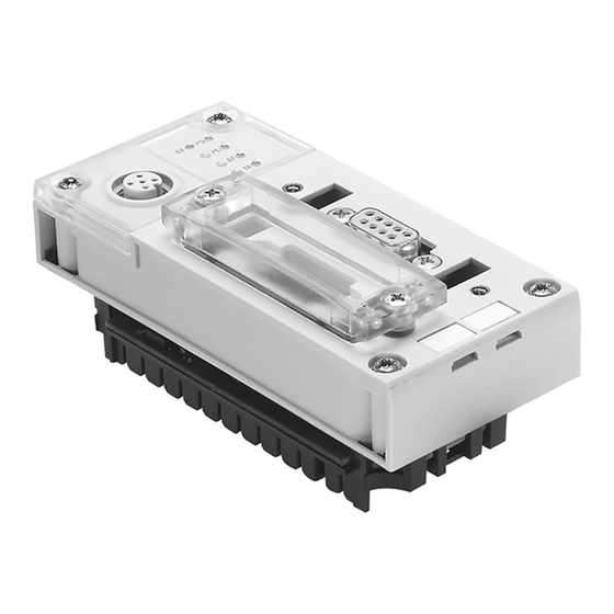
- Page 19 CPX field bus node for PROFIBUS-DP: Bus status and CPX-specific LEDs Service interface for handheld (V24) Field bus connection (9-pin sub-D socket) Cover of the DIL switches Fig. 1/1: Connecting and display elements on the CPX field bus node Festo P.BE-CPX-FB13-EN en 0112NH...
- Page 20 T10. 2. Pull the field bus node carefully and without tilting away from the contact rails of the manifold sub-base. Field bus node CPX-FB13 Manifold sub-base Contact rails Screws Fig. 1/2: Fitting/removing the field bus node Festo P.BE-CPX-FB13-EN en 0112NH...
- Page 21 2. Tighten the screws only by hand. Place the screws so that the self-cutting threads can be used. Tighten the screws with a Torx screwdriver size T10 with torque 0.9...1.1 Nm. Festo P.BE-CPX-FB13-EN en 0112NH...
- Page 22 Fitting 1. Place the cover carefully on the node. Please note Make sure that the seal is seated correctly. • 2. Tighten the two fastening screws at first by hand and then with torque 0.5...0.8 Nm. Festo P.BE-CPX-FB13-EN en 0112NH...
- Page 23 3. Assign an unused station number to the CPX terminal. Set the desired station number (8-position DIL switch, elements 1...7). 4. Set the diagnostic mode (8-position DIL switch, element 8). 5. Fit the cover again (section 1.2.1). Festo P.BE-CPX-FB13-EN en 0112NH...
- Page 24 Fig. 1/3: DIL switch in the field bus node Reserved DIL switches Leave all switch elements of the 2-element DIL switches 1 and 2 at OFF: Reserved Fig. 1/4: Setting of the 2-element DIL switch 1-10 Festo P.BE-CPX-FB13-EN en 0112NH...
- Page 25 CPX terminal will be sent to the master system, e.g. short circuit at the outputs or undervoltage at the valves (see sec- tion 3.5). Device-related diagnosis Device-related diagnosis active inactive Fig. 1/5: Setting the diagnostic mode 1-11 Festo P.BE-CPX-FB13-EN en 0112NH...
- Page 26 The following station numbers are permitted: Protocol Address Permitted station identification numbers PROFIBUS-DP PROFIBUS address 1; ...; 125 Recommendation: Assign the station numbers in ascending order. Assign the station addresses to suit the machine structure of your system. 1-12 Festo P.BE-CPX-FB13-EN en 0112NH...
- Page 27 Set station number: 38 2 + 4 + 32 = 1 + 4 = Fig. 1/7: Examples of set station numbers (binary coded) The following pages contain a summary of the settings for the station numbers. 1-13 Festo P.BE-CPX-FB13-EN en 0112NH...
- Page 28 1. Installation Sta- Sta- tion tion reserved Tab. 1/1: Settings of station numbers 1...31: Position of the DIL switch elements 1-14 Festo P.BE-CPX-FB13-EN en 0112NH...
- Page 29 1. Installation Sta- Sta- tion tion Tab. 1/2: Settings of station numbers 32...63: Position of the DIL switch elements 1-15 Festo P.BE-CPX-FB13-EN en 0112NH...
- Page 30 1. Installation Sta- Sta- tion tion Tab. 1/3: Settings of station numbers 64...95: Position of the DIL switch elements 1-16 Festo P.BE-CPX-FB13-EN en 0112NH...
- Page 31 1. Installation Sta- Sta- tion tion Tab. 1/4: Settings of station numbers 96...125: Position of the DIL switch elements 1-17 Festo P.BE-CPX-FB13-EN en 0112NH...
- Page 32 Core diameter: > 0.64 mm Core cross-sectional area: > 0.34 mm If the Festo IP65 plug is used, cables with a diameter of 5...8 or 7...10 mm are permitted. Bus length Exact specifications on the bus length can be found in section 1.3.2 and in the manuals for your control system.
- Page 33 187.5 1000 m 33.3 m 400 m 20 m 1500 200 m 6.6 m 3000...12000 100 m — Tab. 1/5: Max. field bus length and branch line length for PROFIBUS-DP depending on the baud rate. 1-19 Festo P.BE-CPX-FB13-EN en 0112NH...
- Page 34 There is a 9-pin sub-D socket on the field bus node for con- necting the CPX terminal to the field bus. This connection serves for the incoming and continuing field bus cable. You can connect the CPX terminal with the sub-D plug from Festo (part nos. 18529). Bus connection...
- Page 35 Only connected capacitively CPX field bus node (smaller than actual size) Pin assignment in the plug BF PS A: RxD/TxD-N B: RxD/TxD-P Fig. 1/8: Sub-D plugs from Festo: Pin assignment and screening connection 1-21 Festo P.BE-CPX-FB13-EN en 0112NH...
- Page 36 1. Installation Please note The cable clip in the sub-D plug from Festo is connected internally only capacitively with the metallic outer ring of the plug. This is to prevent equalizing currents flowing through the screening of the field bus cable (Fig. 1/8).
- Page 37 Fit a bus termination to both ends of the bus segment. • Recommendation: Use the sub-D plug from Festo (part no. 18529) for the bus termination. A suitable resistor network is incorporated in the housing of this plug. The bus termination must be switched manually with slide switches.
- Page 38 (data cable B) Pin 3 220 Ω 120 nH Receive/send data N (data cable A) Pin 8 390 Ω Pin 5 Fig. 1/10: Circuit diagram for bus connection network for cable type A as per EN 50170 1-24 Festo P.BE-CPX-FB13-EN en 0112NH...
- Page 39 Siemens Optical Link Module (OLM) for PROFIBUS plus – Siemens Optical Link Plug (OLM) for PROFIBUS (IP20) ® – Harting Han-InduNet Media converter IP65 in combina- tion with adapter cable for Festo valve terminals (optical data transmission in DESINA installation concept). 1-25 Festo P.BE-CPX-FB13-EN en 0112NH...
- Page 40 The current consumption of a CPX terminal depends on the number and type of integrated modules and components. Read the information on power supply as well as on the earthing measures to be carried out in the CPX system manual. 1-26 Festo P.BE-CPX-FB13-EN en 0112NH...
- Page 41 Fig. 1/11: Pin assignment of the system supply (manifold sub-base type CPX-GE-EV-S) Pin assignment 1: Not connected 2: Load voltage 3: 0 V 4: Earth/ground connection Fig. 1/12: Pin assignment of the additional supply (manifold sub-base type CPX-GE-EV-..) 1-27 Festo P.BE-CPX-FB13-EN en 0112NH...
- Page 42 1. Installation 1-28 Festo P.BE-CPX-FB13-EN en 0112NH...
- Page 43 Commissioning Chapter 2 Festo P.BE-CPX-FB13-EN en 0112NH...
- Page 44 ..... . . 2-31 2.3.1 Faultless commissioning, normal operating status ... . . 2-32 Festo P.BE-CPX-FB13-EN en 0112NH...
- Page 45 CPX system manual (P.BE-CPX-SYS-..). Information on commissioning the pneumatic interfaces and I/O modules can be found in the manual for the CPX I/O mod- ules (P.BE-CPX-EA-..). Instructions on commissioning the pneumatics can be found in the relevant pneumatics manual. Festo P.BE-CPX-FB13-EN en 0112NH...
- Page 46 The following FREEZE com- mand causes the input image to be updated. The updated input image is then sent constantly to the master. Return to normal operation: UNFREEZE command. Festo P.BE-CPX-FB13-EN en 0112NH...
- Page 47 Depending on the configuration, the field bus node can occupy status information as logical inputs. Outputs – Counting is module-orientated, irrespective of the posi- tion of the field bus node. – Counting from left to right. Festo P.BE-CPX-FB13-EN en 0112NH...
- Page 48 1 byte I + 1 byte O (Y: CPX-8DE-8DA) Analogue 2-input module 2 words I (U: CPX-2AE-U/I) Analogue 2-output module 2 words O (P: CPX-2AA-U/I) Identifiers can be grouped together Tab. 2/1: Overview of identifiers for CPX modules Festo P.BE-CPX-FB13-EN en 0112NH...
- Page 49 You can only group together modules of the same type: – input modules – output modules Any other module types may be placed between the grouped modules. Further information can be found in the configur- ation example below. Festo P.BE-CPX-FB13-EN en 0112NH...
- Page 50 – 1...16 valve coils, 2 bytes O 16DO (VI: CPX type 03: 1-...VS) – 1...24 valve coils, 3 bytes O 24DO – 1...26 valve coils, 4 bytes O 32DO Tab. 2/2: Overview of identifiers for CPX pneumatic interfaces Festo P.BE-CPX-FB13-EN en 0112NH...
- Page 51 2. Commissioning Configuration example The following CPX terminal is used throughout this manual as the configuration example: Module no.: 4DO 8DI Field bus node CPX-FB13 Multi I/O module 8-input module 4-output module 8-input module Pneumatic interface (set with DIL switch to 1...16 valve coils)
- Page 52 The identifier with the star symbol is used in loca- tion 5. Please note Make sure that the modules are correctly grouped together. This is not checked by the planning software COM PROFIBUS or STEP 7. 2-10 Festo P.BE-CPX-FB13-EN en 0112NH...
- Page 53 Cpx_059e.gsd (German version) – Cpx_059e.gse (International version) Symbol files In order to represent the CPX terminal in your configuration software, you will find symbol files for Festo CPX terminals at the above-mentioned Internet addresses: Normal operating Diagnostic case Special operating...
- Page 54 The following sections describe as an example the most im- portant steps required for configuring the Festo valve ter- minal with the “COM PROFIBUS software or with “STEP 7”. In the following, it is assumed that the user is already familiar with the contents of the manual for the COM PROFIBUS soft- ware or for STEP 7.
- Page 55 ...\SIEMENS\CPBV50\BITMAPS on your PC or programmer. This will make the configur- ation easier. 3. Make entries in the following fields in the mask “Bus parameter” in the menu “Configure:” – Bus profile – Baud rate. 2-13 Festo P.BE-CPX-FB13-EN en 0112NH...
- Page 56 Fig. 2/3: Station selection with COM PROFIBUS 5.0 (explanations see text) 1. Open the following directory in the hardware catalogue: \DP slave\valves\... 1. The Festo valve terminals are listed. (Prerequisites: You must have copied the GSD files as in step 1 of the prepara- tions).
- Page 57 – The PROFIBUS address must be assigned (see above). – Station type “FESTO CPX” must be selected (see above). Configuring Access the dialogue window “Configure” as follows: 1. Double click with the left-hand mouse key or once with the right-hand mouse key on the symbol of the CPX ter- minal.
- Page 58 The module appears in the configuration table. 4. Repeat step 2 for further modules in your CPX terminal. Please note Accept the modules in the configuration table correspon- ding to the physical sequence (from left to right) on your CPX terminal. 2-16 Festo P.BE-CPX-FB13-EN en 0112NH...
- Page 59 In the case of a marked I/O address range, the function “Auto address” carries out an automatic assignment of the free addresses of the system depending on the system limits. This concludes the configuration and address assignment. 2-17 Festo P.BE-CPX-FB13-EN en 0112NH...
- Page 60 STEP 7 project (station GSD). This can cause the updating/reading of new GSD files to appear as if incor- rect. Please inform yourself about handling the station GSD files in the STEP 7 help. 2-18 Festo P.BE-CPX-FB13-EN en 0112NH...
- Page 61 “Bitmap” in HW Config. 3. Process the following entries in the dialogue window “Properties of the DP Master:” – the bus profile – the baud rate. 4. Activate the DP master in the rack. 2-19 Festo P.BE-CPX-FB13-EN en 0112NH...
- Page 62 Fig. 2/5: Station selection with STEP 7 V5.1 – HW Config (The masks shown are not all visible at the same time, see text) 1. If the hardware catalogue is not open: Click on the cata- logue symbol 1. The hardware catalogue now opens. 2-20 Festo P.BE-CPX-FB13-EN en 0112NH...
- Page 63 Field Devices” if you have copied the GSD correctly (see step 1 of the preparations). 3. Pull the folder “FESTO CPX” onto the PROFIBUS line on the DP master (Drag & Drop) 3. The dialogue window “Properties – PROFIBUS Interface”...
- Page 64 The dialogue window “Properties – DP slave” appears. 2. Modify the starting address of the inputs/outputs. Please note With S7-400 controllers, 4 bytes of addresses are in some cases reserved for each DP identifier. This concludes the station selection and configuration. 2-22 Festo P.BE-CPX-FB13-EN en 0112NH...
- Page 65 – (42) (* A: CPX-4DA) CPA pneumatic interface 16DO – (VI: CPX type 12: 1-16VS) Occupies bits 4...7 of output byte 042 automatically. Tab. 2/6: Input and output addresses for the example from Fig. 2/2 2-23 Festo P.BE-CPX-FB13-EN en 0112NH...
- Page 66 2. Commissioning 4DO 8DI Field bus node CPX-FB13 CPA pneumatics Pneumatic interface Fig. 2/7: Addressing the CPX terminal on the example from Fig. 2/2 2-24 Festo P.BE-CPX-FB13-EN en 0112NH...
- Page 67 2.2.1 Parametrizing when the terminal is switched on The parameter PROFI- PLC/ set is loaded into BUS-DP Master the node by the master. The parameter set is distributed to the modules by the node. Fig. 2/8: Sequence of the start parametrizing 2-25 Festo P.BE-CPX-FB13-EN en 0112NH...
- Page 68 3. Click the value of the parameter you wish to modify. A dropdown list with the possible values will open up 4. 4. Modify the value by clicking and confirm with OK. 2-26 Festo P.BE-CPX-FB13-EN en 0112NH...
- Page 69 1. Click the value of the parameter “Diag.Buffer – Mode” or “Diag.Buffer – Error end” A dropdown list with the possible values will open up. 2. Modify the value as follows and confirm with OK. 2-27 Festo P.BE-CPX-FB13-EN en 0112NH...
- Page 70 Fig. 2/10: Parametrizing the diagnostic memory with STEP 7 Possibilities of parametrizing the diagnostic memory (fault end filter): – “Record Coming/going”: Outgoing faults (fault ends) are recorded. – “Record coming only”: Outgoing faults (fault ends) are not recorded. 2-28 Festo P.BE-CPX-FB13-EN en 0112NH...
- Page 71 2. Proceed further as described in “System parameters” under 3. and 4. Fig. 2/11: Parametrizing the module with STEP 7 Please note Module parameters can refer to: – features of the complete module – features of an individual channel of a module. 2-29 Festo P.BE-CPX-FB13-EN en 0112NH...
- Page 72 0.1 ms: It is possible to register shorter sig- nals. (Applies to the complete module). – Modification of the signal extension time to 50 ms: The signal is registered reliably by the controller. (Applies only to the input channel of the 2nd. sensor). 2-30 Festo P.BE-CPX-FB13-EN en 0112NH...
- Page 73 Providing the safety concept of your machine/system permits this, commission the CPX terminal with both operating volt- ages (pins 1 and 2), but without compressed air. You can then test the CPX terminal without triggering undesired reactions. 2-31 Festo P.BE-CPX-FB13-EN en 0112NH...
- Page 74 3 of this manual and in the CPX system manual (P.BE-CPX-SYS-..). Colour Operating status Error treatment Green Normal None lights up Green Normal None lights up LED is off Normal None Tab. 2/7: Normal operating status of the CPX terminal 2-32 Festo P.BE-CPX-FB13-EN en 0112NH...
- Page 75 Diagnosis Chapter 3 Festo P.BE-CPX-FB13-EN en 0112NH...
- Page 76 Read diagnostic buffer with STEP 7 (version 4.x, 5.1) ..3-27 3.7.2 Read device-specific diagnosis with STEP 7 (version 5.1) ..3-29 Festo P.BE-CPX-FB13-EN en 0112NH...
- Page 77 CPX system manual (P.BE-CPX-SYS-..). Information on diagnosing the pneumatic interface and the I/O modules can be found in the manual CPX I/O modules (P.BE-CPX-EA-..). Information on diagnosing the pneumatics can be found in the relevant pneumatics manual. Festo P.BE-CPX-FB13-EN en 0112NH...
- Page 78 Access to all system data of Extended access to diag- Appendix A.3 PROFIBUS DPV1 the CPX terminal via the nostic data in the PLC user field bus. program (e.g. diagnostic memory). Tab. 3/1: Diagnostic possibilities – part 1 Festo P.BE-CPX-FB13-EN en 0112NH...
- Page 79 Tab. 3/2: Diagnostic possibilities – part 2 Please note Note that the diagnostic information shown can depend on the settings (see section 1.2.2) as well as on the parame- trizing (see section 2.2) of the CPX terminal. Festo P.BE-CPX-FB13-EN en 0112NH...
- Page 80 PS: Power system (green) PL: Power load (green) SF: System fault (red) M: Modify (yellow) Fig. 3/1: LEDs of the CPX node The LEDs in their various states are represented as follows: lights up flashes ; Festo P.BE-CPX-FB13-EN en 0112NH...
- Page 81 • circuited or faulty field bus connection – Configuration not Configuration of the master in • correct respect of the modules of the CPX terminal. Tab. 3/3: Error diagnosis with the red LED “BF” Festo P.BE-CPX-FB13-EN en 0112NH...
- Page 82 (default) Power Off/On necessary • Load voltage (valves and Check load voltage connection for the outputs) not applied electronics LED is out Tab. 3/4: Error diagnosis with the LEDs PS and PL Festo P.BE-CPX-FB13-EN en 0112NH...
- Page 83 The system fault LED flashes in accordance with the error class. Error class 1 (simple fault): 1 flash, interval Error class 2 (fault): 2 flashes, interval Error class 3 (serious fault): 3 flashes, interval Tab. 3/5: Error diagnosis with the LED SF Festo P.BE-CPX-FB13-EN en 0112NH...
- Page 84 (see system parameter Force mode; function no. 4402). LED flashes The display of the function Force (LED flashes) has precedence over the display of the setting for system start (LED lights up). Tab. 3/6: Messages of the LED M 3-10 Festo P.BE-CPX-FB13-EN en 0112NH...
- Page 85 The CPX terminal will provide a 16-bit diagnostic interface if you have configured it with option “FB13 DP slave system diagnosis.” Information on the I/O diagnostic interface can be found in the CPX system manual P.BE-CPX-SYS-.. . 3-11 Festo P.BE-CPX-FB13-EN en 0112NH...
- Page 86 One bit is reserved pro module for displaying a current diagnosis. – Channel-related diagnosis (see section 3.5.5). - module number - channel number and type - type of diagnosis (fault number). Device-related diagnosis Module-related diagnosis Channel-related diagnosis Fig. 3/2: Diagnostic possibilities 3-12 Festo P.BE-CPX-FB13-EN en 0112NH...
- Page 87 The diagnostic information is only sent to the master sys- tem if the device-related diagnosis is activated with the DIL switch. In order to do this, set switch element 8 of the 8-element DIL switch to “ON.” 3-13 Festo P.BE-CPX-FB13-EN en 0112NH...
- Page 88 Master address: The address of the master, which parametrized the CPX terminal, is entered in this byte. Ident_number high byte Manufacturer identifier high byte (05 Ident_number low byte Manufacturer identifier low byte (9E Tab. 3/8: Overview of diagnostic bytes: Standard diagnostic information 3-14 Festo P.BE-CPX-FB13-EN en 0112NH...
- Page 89 11 = Module has failed or does not exist (work data invalid) Modules 4...7 Like byte 10 Modules 8...10 Like byte 10 (bits 6 and 7 are reserved) 13...21 Reserved – Tab. 3/9: Overview of device-related diagnosis (fixed at length of 16 bytes) 3-15 Festo P.BE-CPX-FB13-EN en 0112NH...
- Page 90 Channel number and input/output Channel-related diagnostic module z byte 3 Fault type and channel type x, y, z: See explanation in the following text. Tab. 3/11: Overview of diagnostic bytes: Channel-related diagnosis (details in section 3.5.5) 3-16 Festo P.BE-CPX-FB13-EN en 0112NH...
- Page 91 – In the case of several channel-orientated faults on a mod- ule, only the diagnostic message of the channel with the lowest channel number will be entered. – Maximum 11 diagnostic messages can be processed. 3-17 Festo P.BE-CPX-FB13-EN en 0112NH...
- Page 92 1 = CPX terminal does not support the function requested Diag.Invalid_Slave_Response Always 0 (set by CPX terminal) Diag.Prm_Fault Last parametrizing telegram faulty Diag.Master_Lock Always 0 (set by CPX terminal) Valve terminal related bits Tab. 3/12: Diagnostic bits Station status_1 3-18 Festo P.BE-CPX-FB13-EN en 0112NH...
- Page 93 Station status_3 Meaning Explanation 0...6 – Reserved Diag.Ext_Diag_Overflow 1 = CPX terminal has more diagnostic messages than can be buffered or master receives more diagnostic messages than it can buffer. Tab. 3/14: Diagnostic bits station status_3 3-19 Festo P.BE-CPX-FB13-EN en 0112NH...
- Page 94 Module 7 has diagnosis Fig. 3/5: Module-related diagnosis 3.5.5 Channel-related diagnosis 3 bytes of diagnostic data are available for each channel. – Byte 1: Module number – Byte 2: Channel number – Byte 3: Type of diagnosis 3-20 Festo P.BE-CPX-FB13-EN en 0112NH...
- Page 95 000 = reserved 100 = 1 byte 001 = 1 bit 101 = 1 word 010 = 2 bits 110 = 2 words 011 = 4 bits 111 = reserved Fig. 3/8: Channel-related diagnostic byte 3 3-21 Festo P.BE-CPX-FB13-EN en 0112NH...
- Page 96 Parametrizing fault (lower limit) Reserved Parametrizing fault (upper limit) Reserved Reserved Reserved Reserved Reserved Reserved Reserved Reserved Reserved Slave has no bus connection Reserved Channel failure Tab. 3/15: Fault types (byte 3 of the channel-related diagnosis) 3-22 Festo P.BE-CPX-FB13-EN en 0112NH...
- Page 97 – Single-solenoid valves move to the basic position. – Double-solenoid valves remain in the current position. – Mid-position valves move to the mid-position (depend- ing on valve type: pressurized, exhausted or blocked). 3-23 Festo P.BE-CPX-FB13-EN en 0112NH...
- Page 98 Almost all configuration programs contain the function “Response monitoring.” For the operating modes named, the time specified corresponds to the drop-off time of the valves and electric outputs. Further details on response monitoring can be found in the relevant manuals. 3-24 Festo P.BE-CPX-FB13-EN en 0112NH...
- Page 99 OB is programmed DP slave QVZ: Quitting delay OB: Organisation module PEU: Periphery not clear Tab. 3/16: Fault reaction of the control system Further details can be found in the relevant manuals for the control systems. 3-25 Festo P.BE-CPX-FB13-EN en 0112NH...
- Page 100 (see mask “Properties – DP slave” in HW Config) When errors occur, output error code RET_VAL:=MW100 Pointer at start of data range for diagnosis RECORD:=P#M110.0 BYTE 64 and length of diagnostic data Reading concluded BUSY:=M10.0 Fig. 3/9: Program example in STL 3-26 Festo P.BE-CPX-FB13-EN en 0112NH...
- Page 101 3. Select the register “Diagnostic Buffer” 4. 4. Mark the event and read the details on the event. These supply more detailed information on the further pro- cedure and depend on the S7 controller 5 used. 3-27 Festo P.BE-CPX-FB13-EN en 0112NH...
- Page 102 3. Diagnosis Fig. 3/10: Online diagnosis via diagnostic buffer (explanation see text) 3-28 Festo P.BE-CPX-FB13-EN en 0112NH...
- Page 103 2. Click with the right-hand mouse key on the symbol of the CPX terminal 1. Click on “Module information” in the con- text menu which now appears. The dialogue window “Module information” appears. 3. Select the register “DP Slave Diagnostics.” 4. Read the diagnostic information 2. 3-29 Festo P.BE-CPX-FB13-EN en 0112NH...
- Page 104 3. Diagnosis Fig. 3/11: Device-related diagnosis with STEP 7 V5.1 (explanation see text) 3-30 Festo P.BE-CPX-FB13-EN en 0112NH...
- Page 105 Technical appendix Appendix A Festo P.BE-CPX-FB13-EN en 0112NH...
-
Page 106: Table Of Contents
..........Technical specifications of field bus node CPX-FB13 . -
Page 107: Technical Appendix
Technical specifications of field bus node CPX-FB13 General General technical specifications See CPX system manual: – P.BE-CPX-SYS-.. Protection class as per EN 60529, CPX-FB13 fitted IP65 completely, plug connector inserted or provided with protective cap Protection against electric shock By means of PELV power units... -
Page 108: Operation With The General Dp Master
A. Technical appendix Operation with the general DP master The Festo CPX terminal can be controlled from any PLC, PC or industrial PC with a PROFIBUS-DP module in accordance with EN 50170 (DIN 19245). Information on the functions FREEZE, SYNC and the DP ident- ifiers can be found in section 2.1.1. - Page 109 Bit 6 Explanation Lock_Req Min T + slave parameter may be overwritten CPX terminal released for other masters CPX terminal blocked for other masters CPX terminal released for other masters Tab. A/1: Octet 1: Station status Festo P.BE-CPX-FB13-EN en 0112NH...
- Page 110 8...198 User_Prm_Data Information on the slave-specific parameters can be found in the section 2.2 and the CPX system manual P.BE-CPX-SYS-.. as well as in the manual for the I/O modules P.BE-CPX-EA-.. . Tab. A/2: Further octets Festo P.BE-CPX-FB13-EN en 0112NH...
-
Page 111: Send Configuration Data
Chk_Cfg The configuration data are transmitted to the CPX terminal by the DP master with the function Chk_Cfg. Overview of parameters: Octet 1-n: DP identifier Permitted identifiers for the Festo CPX terminal: Module Occupied bytes Identifier (order code) EN 50170 Field bus node –... - Page 112 (VI: CPX type 03: 1-..VS) 1 byte O – 1...16 valve coils 2 bytes O – 1...24 valve coils 3 bytes O – 1...26 valve coils 4 bytes O Tab. A/4: Overview of identifiers for CPX pneumatic interfaces Festo P.BE-CPX-FB13-EN en 0112NH...
- Page 113 DIL switch to 1...16 valve coils. be configured correctly accord- (VI: CPX type 12: 1-16VS) ing to the connected pneu- matics. Tab. A/5: Example of the configuration of a CPX terminal (see Fig. 2/2) with different modules and CPA pneumatics Festo P.BE-CPX-FB13-EN en 0112NH...
-
Page 114: Error Treatment
Please note With the function Data_Exchange, the CPX terminal ex- pects the output information for the valves and electric outputs. The input information is sent to the master as a reply telegram. A-10 Festo P.BE-CPX-FB13-EN en 0112NH... - Page 115 (Pneumatic interface in location 6) Bit 0: Output t+8 Bit 1: Output t+9 Bit 7: Output t+15 Two 4DO modules are grouped together in this byte. x, y, z, t, u, v, w = Address offset of master module A-11 Festo P.BE-CPX-FB13-EN en 0112NH...
-
Page 116: Implemented Functions And Service Access Points (Sap
– MSAC_C1: For masters of class 1 (e.g. PLC), fixed service access points. – MSAC_C2: For masters of class 2 (e.g. PC/pro- grammer), dynamic use, service access points are specified when connections are set up. A-12 Festo P.BE-CPX-FB13-EN en 0112NH... -
Page 117: Bus Parameters/Reaction Times
The delay time within the CPX terminal is very brief. It is con- siderably less than 1 ms, irrespective of the equipment fitted on your CPX terminal. Please refer to the manual for your controller for ascertaining the total time required for transmission. A-13 Festo P.BE-CPX-FB13-EN en 0112NH... -
Page 118: Access To The Cpx Terminal Via Dpv1
1 but on the line of the field bus node in the configuration table. The mask “Properties – DP slave” appears. 2. Select the register “Parameter Assignment” and modify the value of the “DPV1-Services” to “S7 compatible” (see following diagram). 3. Confirm with OK. A-14 Festo P.BE-CPX-FB13-EN en 0112NH... - Page 119 If faults occur, output fault code RET_VAL :=MW100 Target range for data record read and length of data record RECORD :=P#M110.0 BYTE 8 Reading in process BUSY :=M10.0 Fig. A/2: Example program for reading out the diagnostic memory status A-15 Festo P.BE-CPX-FB13-EN en 0112NH...
- Page 120 Fig. A/3: Example program for transmitting the diagnostic memory status Standard-conform Set the DPV1 compatibility for standard-conform access to the data records on “Standard” (see above under “Setting the DPV1 compatibility”). Use function module DP_RDREC for reading and DP_WRREC for writing data. A-16 Festo P.BE-CPX-FB13-EN en 0112NH...
-
Page 121: Data Records
Index 16...30: Module data and para- meters (see Tab. A/11) Fig. A/4: Data model of the DPV1 access with the CPX-FB13 The following tables show the relationship between access to parameters and data with DPV1 and with the function numbers. Further information on the function numbers can be found in the Appendix to the CPX system manual P.BE-CPX-SYS-.. - Page 122 Diagnostic memory 3480...3487 parameters Diagnostic memory 3488...3497 Entry 0 Diagnostic memory 3498...3507 Entry 1 Diagnostic memory Entry ... Diagnostic memory 3878...3887 Entry 39 Delete diagnostic – memory Siemens S7 Tab. A/8: Slot 1: System parameters A-18 Festo P.BE-CPX-FB13-EN en 0112NH...
- Page 123 Slot 3: Indexed addressing of the objects Index Name Length Access Data Function no. [byte] record number Command box – Read box – Write box – *) Siemens S7 Tab. A/10: Slot 3: Indexed addressing of the objects A-19 Festo P.BE-CPX-FB13-EN en 0112NH...
- Page 124 In the following, entry 0 of the diagnostic memory will be read out indirectly via the command box. 1. Assign the command box as follows: Byte Contents Slot no. Index no. Offset – Example – 2. Read out the diagnostic memory with the read box. A-20 Festo P.BE-CPX-FB13-EN en 0112NH...
- Page 125 Module Force outputs – Module Force outputs – Module Force inputs – Module Force inputs – m = Module number (counting from left to right, beginning with 0) Siemens S7 Tab. A/11: Module data and parameters A-21 Festo P.BE-CPX-FB13-EN en 0112NH...
- Page 126 A. Technical appendix A-22 Festo P.BE-CPX-FB13-EN en 0112NH...
- Page 127 Index Appendix B Festo P.BE-CPX-FB13-EN en 0112NH...
- Page 128 ............Festo P.BE-CPX-FB13-EN en 0112NH...
- Page 129 ....... . . 1-26 Cyclic exchange of data ......A-10 Festo P.BE-CPX-FB13-EN en 0112NH...
- Page 130 A-15 General DP master ....... . Festo P.BE-CPX-FB13-EN en 0112NH...
- Page 131 ......2-25 System parameters ......2-26 Festo P.BE-CPX-FB13-EN en 0112NH...
- Page 132 System supply ........1-27 Festo P.BE-CPX-FB13-EN en 0112NH...
- Page 133 ........A-11 Festo P.BE-CPX-FB13-EN en 0112NH...
- Page 134 B. Index Festo P.BE-CPX-FB13-EN en 0112NH...
Need help?
Do you have a question about the CPX-FB13 and is the answer not in the manual?
Questions and answers