Table of Contents
Advertisement
Quick Links
Advertisement
Table of Contents

Related Manuals for Ever Power Systems POWERLINE RT PLUS 1000

Summary of Contents for Ever Power Systems POWERLINE RT PLUS 1000
-
Page 2: Table Of Contents
EVER POWERLINE RT PLUS UPS Operating Manual INDEX INTRODUCTION ..............................3 GENERAL FEATURES OF THE UPS UNIT ....................4 SAFETY INSTRUCTIONS AND RECOMMENDATIONS ................6 TECHNICAL DESCRIPTION .......................... 12 UNPACKING THE PRODUCT ........................... 12 What’s in the box? ............................12 ELEMENTS OF THE UPS - REAR PANEL ....................... 13 BATTERY MODULE DESIGN –... -
Page 3: Introduction
EVER POWERLINE RT PLUS UPS Operating Manual INTRODUCTION Thank you for purchasing the EVER POWERLINE RT PLUS UPS system. This UPS unit has been designed and engineered to provide the highest standard of protection against power failure. We hope that the purchased UPS unit will meet your expectations. -
Page 4: General Features Of The Ups Unit
EVER POWERLINE RT PLUS UPS Operating Manual GENERAL FEATURES OF THE UPS UNIT The POWERLINE RT PLUS UPS units are ON-LINE (VFI) class devices, designed to work with equipment supplied from ~ 230 VAC single-phase electric power mains. They provide energy for practically any device whose power rating is not greater than the UPS unit's power rating. - Page 5 EVER POWERLINE RT PLUS UPS Operating Manual Remote Emergency Power Off (Remote EPO) functionality which interrupts power supply from the UPS output to loads in extreme situations or in emergency (e.g. fire). Remote On/Off (ROO) function for remotely starting and shutting down the UPS, ...
-
Page 6: Safety Instructions And Recommendations
EVER POWERLINE RT PLUS UPS Operating Manual SAFETY INSTRUCTIONS AND RECOMMENDATIONS A) General considerations CAUTION! Before starting the procedures described in this manual, please read the general safety instructions (including the instructions found in this document), health & safety information, environmental protection information and legal regulations that may apply. - Page 7 EVER POWERLINE RT PLUS UPS Operating Manual equivalent) text should be used on such warning labels: DISCONNECT THE UPS SYSTEM BEFORE STARTING WORK ON THIS CIRCUIT. CAUTION! Opening the unit’s casing may result in electric shock. CAUTION! Do not touch any electrical connectors, terminals and internal metal elements, unless power supply has been properly disconnected.
- Page 8 EVER POWERLINE RT PLUS UPS Operating Manual CAUTION! Before connecting any cables or making any connections within the UPS unit or in the electrical system, make sure there is no dangerous voltage on electrical terminals and cables in the system. CAUTION! The UPS may only be connected to a power system with indicated rated voltage, with a suitable grounding connection installed.
- Page 9 EVER POWERLINE RT PLUS UPS Operating Manual To reduce the risk of electric shock (in case the grounding cannot be checked), the unit must be disconnected from the mains before installation or connecting to other equipment. The power lead may only be reconnected after making all required connections.
- Page 10 EVER POWERLINE RT PLUS UPS Operating Manual There may be voltage on the UPS unit's output terminals, even if the UPS is disconnected from the building's electrical system (due to presence of power in the unit's internal batteries and/or battery packs). ...
- Page 11 EVER POWERLINE RT PLUS UPS Operating Manual Disconnect the device from the mains before cleaning. Do not use liquid or sprayed cleaning agents. UPS units may only be disassembled by suitably qualified service technicians. E) Transport and packaging requirements ...
-
Page 12: Technical Description
- a warranty card, - a user's guide. Depending on the UPS unit: POWERLINE RT PLUS 1000 - 1 x power cord CEE 7/7 - IEC 320 C13 10 A, - 2 x power cords IEC C13 - IEC C14 10 A. -
Page 13: Elements Of The Ups - Rear Panel
2. Controlled output sockets IEC 320 C13 (10 A) 3. Non-controlled output sockets IEC 320 C13 (10 A) Fig. 1: View of the rear panel of POWERLINE RT PLUS 1000 4. SNMP card's compartment 5. External battery modules terminal 6. Fan 7. -
Page 14: Battery Module Design - Rear Panel
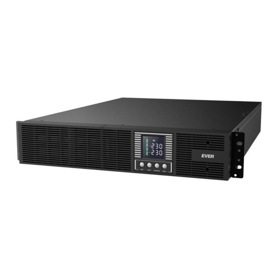
2. Shut down button (OFF) 3. Confirmation button (ENTER) 4. Exit button (ESC) 5. LCD display Fig. 6: View of the front panel of the POWERLINE RT PLUS 1000 unit Technical Support, phone: +48 61 6500 400 www.ever.eu 2019-11-25 11:43... - Page 15 EVER POWERLINE RT PLUS UPS Operating Manual Table 1. Functions of the control panel buttons Button Function Description When the UPS is not on logically (not operating in back-up or normal mode), Switching the unit on press and keep the button depressed for over 1 second to switch the unit on logically logically.
-
Page 16: Lcd Display Icons
EVER POWERLINE RT PLUS UPS Operating Manual Table 2. Sound signals for specific states of the UPS unit Event Sound signal Operation modes: MAINS, No sound signal ECO, STANDBY, INVERTER BACKUP (battery) mode Sound signal every 10 s. Can be activated / deactivated through menu 009 or through PowerSoft. -
Page 17: Description Of Lcd Display Icons
EVER POWERLINE RT PLUS UPS Operating Manual DESCRIPTION OF LCD DISPLAY ICONS Table 3. Description of LCD display icons Symbol Description 1 - MUTE function indicator The icon indicates the activation / deactivation of sound signal when the UPS is in the backup (battery) or bypass mode. -
Page 18: Operation Mode
EVER POWERLINE RT PLUS UPS Operating Manual The UPS operates in back-up (battery) mode - there is no mains power supply or threshold frequency value or effective value of supply voltage are exceeded. If the batteries are used up (and must be replaced), the icon flashes. - Page 19 EVER POWERLINE RT PLUS UPS Operating Manual BYPASS mode. The BYPASS mode is activated when the UPS unit is overloaded (the option "go to BYPASS if overloaded" option must be activated - the option can be activated in PowerSoft) or when an overriding command is given from the user interface (ENTER and ESC buttons are pressed simultaneously).
-
Page 20: Menu Structure - Configuration Of Ups Unit
EVER POWERLINE RT PLUS UPS Operating Manual the UPS operates in frequency converter mode. The function may be activated via the LCD display (settings menu 005). The UPS may be loaded up to 60% of its rated power in the inverter mode. -
Page 21: Protection
EVER POWERLINE RT PLUS UPS Operating Manual [dis] – Disabled INVERTER mode Disabled [EnA] – Enabled Selecting the EPO function (remote emergency power off) EPO / ROO* or ROO function (remote ON/OFF) 0bP / 1bP / 2bP / 3bP Number of battery / 4bP / 5bP / 6bP / modules 7bP / 8bP / 9bP / AbP... -
Page 22: Short-Circuit Protection
EVER POWERLINE RT PLUS UPS Operating Manual If the overload exceeds 120% of the rated power and the function "switch to BYPASS if overloaded" is enabled, the UPS unit will promptly switch to the BYPASS mode (message A64). When the overload condition ceases, the unit remains in the BYPASS mode. -
Page 23: Installation
EVER POWERLINE RT PLUS UPS Operating Manual enters the EMERGENCY mode (error code A66). The output voltage will be restored only after the user’s intervention to reset the trigger to the disabled position (trigger's default state) and to switch the UPS logically on again. The EPO connection contacts show safe voltage levels isolated from the remaining UPS unit systems. -
Page 24: Input Installation
EVER POWERLINE RT PLUS UPS Operating Manual UPS may only be connected to a ~230V mains socket equipped with a grounding bolt. All POWERLINE RT PLUS series UPS units were designed to operate as free- standing units (tower versions) and for installation in 19" rack cabinets (rack versions). -
Page 25: Output Installation
EVER POWERLINE RT PLUS UPS Operating Manual Output installation Although two types of pin configuration are allowed for the input side, the output installation must be done specifically according to this manual, to prevent UPS damage. Fig. 10 shows the diagrams of correct and incorrect output configurations. CAUTION! Only TN-S configuration is allowed for the UPS output installation. -
Page 26: Installation Of The Ups With A Battery Module
EVER POWERLINE RT PLUS UPS Operating Manual Fig. 12: Attaching the feet kit to the UPS 4. Use the supplied plugs to cover the unused mounting openings (Fig. 13). Fig. 13. Installation of plugs Installation of the UPS with a battery module Up to 10 battery modules may be connected to the UPS. - Page 27 EVER POWERLINE RT PLUS UPS Operating Manual Fig. 14: Attaching the feet kit to the UPS and the module 4. Use the supplied plugs to cover the unused mounting openings (Fig. 15). Fig. 15. Installation of plugs 5. Remove the covers of the battery module sockets in the UPS and the battery module (Fig.
-
Page 28: Rack Version Ups Installation
EVER POWERLINE RT PLUS UPS Operating Manual Fig. 17. Installation of plugs 7. Connect the battery module detection cables and the cables supplying power to the internal charger of the battery modules (Fig. 18). Fig. 18: Connecting the UPS and the modules CAUTION! After switching the UPS on, use its menu to configure the number of connected battery modules (1 - 10). - Page 29 EVER POWERLINE RT PLUS UPS Operating Manual To install the UPS in the rack version, use the Rack Kit (available as an option). 2U worth of free space should be left in the cabinet. To install the UPS, follow these steps: 1.
- Page 30 EVER POWERLINE RT PLUS UPS Operating Manual Fig. 22: Installation of the UPS inside the cabinet Technical Support, phone: +48 61 6500 400 www.ever.eu 2019-11-25 11:43...
-
Page 31: Installation Of The Ups With A Battery Module
EVER POWERLINE RT PLUS UPS Operating Manual Installation of the UPS with a battery module CAUTION! Taking into account the considerable weight of the devices, we recommend that two persons work together to install the UPS and the battery module in the rack cabinet. CAUTION! The battery module should be installed directly under the UPS unit. -
Page 32: Disconnecting The Battery Module
EVER POWERLINE RT PLUS UPS Operating Manual 5. Remove the covers of the battery module sockets in the UPS and the battery module (Fig. 16). 6. Make a connection between the UPS and the battery module with the supplied cable. Install the socket covers (Fig. 17). 7. -
Page 33: First Start-Up Of The Ups
EVER POWERLINE RT PLUS UPS Operating Manual 6. Disconnect the cable detecting the battery module from the UPS and the battery module. 7. In case of the rack version UPS and the battery module, remove the battery module from the cabinet. CAUTION! If only the UPS is to be used, change the number of battery modules in the menu to 0. -
Page 34: Starting Up The Ups Unit (Power Supply From The Mains)
EVER POWERLINE RT PLUS UPS Operating Manual STARTING UP THE UPS UNIT (power supply from the mains) Once the UPS unit is correctly connected, start the unit by following these steps in sequence: 1. Make sure the UPS unit's power cord is connected. 2. - Page 35 EVER POWERLINE RT PLUS UPS Operating Manual 1. Press the OFF button and keep it depressed for over 1 second to switch the UPS off. The UPS unit will disconnect the power from the output sockets and will switch to the standby mode. 2.
-
Page 36: Replacing The Ups Unit's Internal Battery
EVER POWERLINE RT PLUS UPS Operating Manual REPLACING THE UPS UNIT'S INTERNAL BATTERY The battery should be replaced if the UPS unit's operating time in the backup (battery) mode is excessively short or a flashing icon is displayed. To order a new battery, contact service support. -
Page 37: Replacing The Battery In The Ups
EVER POWERLINE RT PLUS UPS Operating Manual REPLACING THE BATTERY IN THE UPS CAUTION! Battery replacement can be conducted only when the UPS is in horizontal position (Rack version). Performing the operation in any other position may cause damage to the device. To replace the battery inside the UPS, follow these steps: 1. - Page 38 EVER POWERLINE RT PLUS UPS Operating Manual Fig. 26: Removing and installing the battery chamber 5. Make sure the dimensions and type of replacement batteries satisfy the technical parameters (are identical as the parameters of the old batteries). Replace the old batteries with new ones exercising special caution. 6.
-
Page 39: Replacing The Batteries In The Battery Module
EVER POWERLINE RT PLUS UPS Operating Manual 8. Install the battery terminal cover and the front panel (Fig. 28). Fig. 28: Installation of the terminal cover and the front panel REPLACING THE BATTERIES IN THE BATTERY MODULE CAUTION! Battery replacement can be conducted only when the UPS is in horizontal position (Rack version). - Page 40 EVER POWERLINE RT PLUS UPS Operating Manual Fig. 29. Removing the panel 5. Slide out the battery chamber and the battery (Fig. 30). Fig. 30: Removing and installing the battery chamber CAUTION! The battery chamber slides out completely from the module housing.
- Page 41 EVER POWERLINE RT PLUS UPS Operating Manual 8. Connect the battery chamber's terminal to the battery module's terminal (Fig. 31). Fig. 31: Connecting the battery terminal 9. Install the cover with the battery terminal and the battery module's front panel (Fig.
-
Page 42: Communication With Pc
EVER POWERLINE RT PLUS UPS Operating Manual COMMUNICATION WITH PC To establish communication between the PC and the UPS, the user can choose to use the RS232 or USB interface or the Ethernet port (optional equipment). The UPS unit is managed via remote control systems (PC or server) with PowerSoft freeware. -
Page 43: Operating Instructions
EVER POWERLINE RT PLUS UPS Operating Manual The following functionalities are implemented in the network card: SNMP agent – provides the management of the power supply system using the PowerSoft management software or another type of management / control software package installed by the user. -
Page 44: Interaction With Electrical Generators
EVER POWERLINE RT PLUS UPS Operating Manual WARNING! Never attempt to open the battery. Always ensure suitable battery protection against potential damage. Spilled electrolyte is harmful to the eyes and skin, and could be toxic. INTERACTION WITH ELECTRICAL GENERATORS The POWERLINE RT PLUS UPS units are ONLINE (VFI) class units designed to synchronize voltage with the mains voltage. -
Page 45: Disposal
EVER POWERLINE RT PLUS UPS Operating Manual CAUTION: Battery life depends on the frequency, the manner of use and ambient temperature. The battery used in the UPS unit described in this manual has a design life of 5 years. After that time, battery capacity, reliability and charging intervals will be considerably reduced. - Page 46 EVER POWERLINE RT PLUS UPS Operating Manual Customer Service Department to arrange maintenance and/or replacement of batteries or the complete UPS unit. Technical Support, phone: +48 61 6500 400 www.ever.eu 2019-11-25 11:43...
-
Page 47: Technical Parameters
EVER POWERLINE RT PLUS UPS Operating Manual TECHNICAL PARAMETERS POWERLINE RT PLUS PARAMETERS \ TYPE POWERLINE RT PLUS POWERLINE RT PLUS POWERLINE RT PLUS 1000 2000 3000 Index T/PWPLRT-111000/00 T/PWPLRT-112000/00 T/PWPLRT-113000/00 Output power (apparent / active) 1000 VA / 1000 W 2000 VA / 2000 W 3000 VA / 3000 W GENERAL AND ENVIRONMENTAL DATA... - Page 48 EVER POWERLINE RT PLUS UPS Operating Manual POWERLINE RT PLUS PARAMETERS \ TYPE POWERLINE RT PLUS POWERLINE RT PLUS POWERLINE RT PLUS 1000 2000 3000 Index T/PWPLRT-111000/00 T/PWPLRT-112000/00 T/PWPLRT-113000/00 Output power (apparent / active) 1000 VA / 1000 W 2000 VA / 2000 W 3000 VA / 3000 W BATTERIES AND BACKUP TIMES Internal batteries...
-
Page 49: Diagnostics Of Errors Reported By The Ups
EVER POWERLINE RT PLUS UPS Operating Manual Load 60 – 80% bottom input voltage threshold 140 V AC ± 5% Load 80 – 100% bottom input voltage threshold 160 V AC ± 5% Can be configured by software and LCD display. With prolonged operation with recommended load. - Page 50 EVER POWERLINE RT PLUS UPS Operating Manual The battery voltage is lower than the battery shut down level specified for this UPS unit. A59 – Batteries Make sure all batteries are properly connected. If the Possible causes include a blown fuse, an disconnected situation persists, contact service support.
- Page 51 EVER POWERLINE RT PLUS UPS Operating Manual Disconnect all receivers from the UPS unit. The UPS unit has detected improper Short circuit Make sure that the short circuit is removed output impedance level. before switching the device back on. Disconnect some receivers from the UPS Overload UPS output overloaded unit.
-
Page 52: Legal Regulations And Warranty
EVER POWERLINE RT PLUS UPS Operating Manual LEGAL REGULATIONS AND WARRANTY DECLARATION OF CONFORMITY The UPS design conforms to the appropriate subject matter standards. The declaration of conformity is published at www.ever.eu. WARRANTY A separate document attached to the product constitutes the warranty. The document must meet all formal requirements (e.g.
Need help?
Do you have a question about the POWERLINE RT PLUS 1000 and is the answer not in the manual?
Questions and answers