
Related Manuals for IEI Technology ITG-100AI


Summary of Contents for IEI Technology ITG-100AI
- Page 1 ITG-100AI Embedded System MODEL: ITG-100AI Fanless Embedded System with Intel® Atom™ x5-E3930, VGA , GbE, Two RS-232/422/485, Two USB 3.0 and RoHS Compliant User Manual Page i Rev. 1.00 – October 2, 2019...
- Page 2 ITG-100AI Embedded System Revision Date Version Changes October 2, 2019 1.00 Initial release Page ii...
- Page 3 ITG-100AI Embedded System Copyright COPYRIGHT NOTICE The information in this document is subject to change without prior notice in order to improve reliability, design and function and does not represent a commitment on the part of the manufacturer. In no event will the manufacturer be liable for direct, indirect, special, incidental, or consequential damages arising out of the use or inability to use the product or documentation, even if advised of the possibility of such damages.
- Page 4 ITG-100AI Embedded System Manual Conventions WARNING Warnings appear where overlooked details may cause damage to the equipment or result in personal injury. Warnings should be taken seriously. CAUTION Cautionary messages should be heeded to help reduce the chance of losing data or damaging the product.
-
Page 5: Table Of Contents
ITG-100AI Embedded System Table of Contents 1 INTRODUCTION ......................1 1.1 O ........................2 VERVIEW 1.2 F ........................2 EATURES 1.3 T ..................3 ECHNICAL PECIFICATIONS 1.4 S ........................ 4 ANEL 1.5 F ......................5 RONT ANEL 1.6 P ....................6... - Page 6 ITG-100AI Embedded System 4.1.2 Using Setup ...................... 26 4.1.3 Getting Help ..................... 27 4.1.4 Unable to Reboot after Configuration Changes ..........27 4.1.5 BIOS Menu Bar ....................27 4.2 M ........................28 4.3 A ....................... 29 DVANCED 4.3.1 ACPI Settings ....................30 4.3.2 F81866 Super IO Configuration ..............
- Page 7 ITG-100AI Embedded System B.1.1 General Safety Precautions ................64 B.1.2 Anti-static Precautions ..................65 B.1.3 Product Disposal ..................... 66 B.2 M ............67 AINTENANCE AND LEANING RECAUTIONS B.2.1 Maintenance and Cleaning ................67 B.2.2 Cleaning Tools ....................67 C BIOS MENU OPTIONS ..................... 69 D TERMINOLOGY .......................
- Page 8 ITG-100AI Embedded System List of Figures Figure 1-1: ITG-100AI ........................2 Figure 1-2: ITG-100AI Side Panel ....................4 Figure 1-3: ITG-100AI Front Panel ....................5 Figure 1-4: Physical Dimensions (mm) ..................6 Figure 3-1: Bottom Cover Retention Screws ................12 Figure 3-2: Bottom Cover Installation ..................
- Page 9 ITG-100AI Embedded System List of Tables Table 1-1: Technical Specifications ....................4 Table 2-1: Package List Contents ....................9 Table 3-1: RJ-45 RS-232/422/485 Serial Port Pinouts ............... 19 Table 3-2: DB-9 RS-232/422/485 Connector Pinouts ..............20 Table 4-1: BIOS Navigation Keys ....................27...
- Page 10 ITG-100AI Embedded System BIOS Menus BIOS Menu 1: Main ........................28 BIOS Menu 2: Advanced ......................29 BIOS Menu 3: ACPI Configuration ....................30 BIOS Menu 4: Super IO Configuration ..................31 BIOS Menu 5: Serial Port 1 Configuration Menu ............... 31 BIOS Menu 6: Hardware Monitor ....................
-
Page 11: Introduction
ITG-100AI Embedded System Chapter Introduction Page 1... -
Page 12: Overview
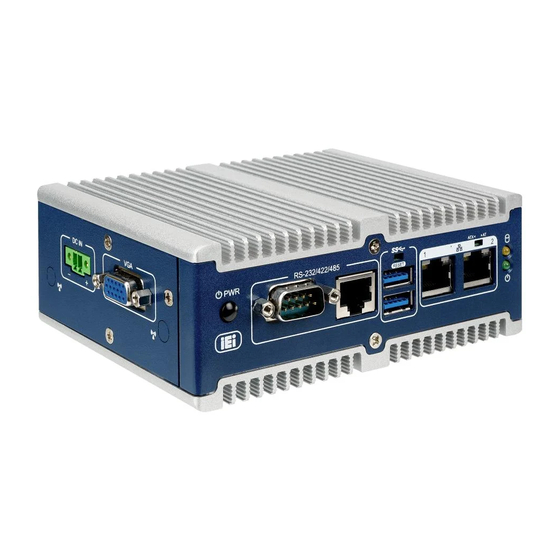
1.1 Overview Figure 1-1: ITG-100AI The ITG-100AI embedded system is a fanless system with one VGA port for display. It accepts an Intel® Atom™ x5-E3930 processor and supports one 204-pin DDR3L SO-DIMM module pre-installed with 8 GB memory. Two RS-232/422/485 serial ports and two USB 3.1 GEN 1 ports ensure simplified connectivity to a variety of external... -
Page 13: Technical Specifications
ITG-100AI Embedded System 1.3 Technical Specifications The ITG-100AI technical specifications are listed in Table 1-1. Model Name ITG-100AI AI Accelerator Mustang-MPCIE-MX2 Chassis Color Blue & Silver Dimensions (WxDxH) 137 x 102.8 x 50 (mm) System Fan Fanless Chassis Construction Extruded aluminum alloy Motherboard Intel®... -
Page 14: Side Panel
Programmable 1~255 sec/min Supported OS Win10/Linux Ubuntu 16.04 LTS Table 1-1: Technical Specifications 1.4 Side Panel The side panel of the ITG-100AI has the following features (Figure 1-2): 1 x 9~36V DC IN 1 x VGA connector Figure 1-2: ITG-100AI Side Panel... -
Page 15: Front Panel
ITG-100AI Embedded System 1.5 Front Panel The front panel of the ITG-100AI has the following features (Figure 1-3): 1 x AT/ATX Switch 1 x HDD LED 1 x Power button 1 x Power LED 1 x Reset button ... -
Page 16: Physical Dimensions
ITG-100AI Embedded System 1.6 Physical Dimensions The physical dimensions of the ITG-100AI are shown below: Figure 1-4: Physical Dimensions (mm) Page 6... -
Page 17: Unpacking
ITG-100AI Embedded System Chapter Unpacking Page 7... -
Page 18: Unpacking
If some of the components listed in the checklist below are missing, please do not proceed with the installation. Contact the IEI reseller or vendor you purchased the ITG-100AI from or contact an IEI sales representative directly. To contact an IEI sales representative, please send an email to sales@iei.com.tw. -
Page 19: Table 2-1: Package List Contents
ITG-100AI Embedded System Quantity Item and Part Number Image Adapter (P/N: 63040-010036-210-RS) Power cord Power cable (P/N: 32102-045700-100-RS) 1 x RJ-45 to DB-9 COM port cable Mounting Bracket Screws (M3*6) for DIN mount Table 2-1: Package List Contents Page 9... -
Page 20: Installation
ITG-100AI Embedded System Chapter Installation Page 10... -
Page 21: Anti-Static Precautions
Electric shock and personal injury might occur if the rear panel of the ITG-100AI is opened while the power cord is still connected to an electrical outlet. -
Page 22: Bottom Cover Removal And Re-Installation
Air Circulation: Make sure there is sufficient air circulation when installing the ITG-100AI. The ITG-100AI’s cooling vents must not be obstructed by any objects. Blocking the vents can cause overheating of the ITG-100AI. Leave at least 5 cm of clearance around the ITG-100AI to prevent overheating. -
Page 23: So-Dimm Installation
ITG-100AI. To install a SO-DIMM into a SO-DIMM socket, please follow the steps below. Step 1: Remove the bottom cover from the ITG-100AI. Please follow the instruction described in Section 3.3. Step 2: Locate the SO-DIMM socket on the motherboard (Figure 3-3). -
Page 24: Figure 3-3: So-Dimm Socket
ITG-100AI Embedded System Figure 3-3: SO-DIMM Socket Step 3: Align the SO-DIMM with the socket. The SO-DIMM must be oriented in such a way that the notch in the middle of the SO-DIMM must be aligned with the plastic bridge in the socket (Figure 3-4). -
Page 25: Wireless Lan Module Installation (Optional)
Section 3.3. 3.5 Wireless LAN Module Installation (Optional) The ITG-100AI has an M.2 slot for WLAN card installation. The M.2 card slot is located under the accelerator card. To install the optional wireless LAN (WLAN) module, please follow the steps below. -
Page 26: Figure 3-6: Wlan M.2 Card Slot Location
ITG-100AI Embedded System Figure 3-6: WLAN M.2 Card Slot Location Step 4: Line up the notch on the module with the notch on the slot. Slide the WLAN card into the socket at an angle of about 20º (Figure 3-7). -
Page 27: Rs-232/422/485 Serial Port Connection
ITG-100AI Embedded System Figure 3-8: Securing the WLAN Card 3.6 RS-232/422/485 Serial Port Connection The ITG-100AI has two RS-232/422/485 serial port connectors on the bottom panel. One is DB-9 connector and the other is RJ-45 connector. 3.6.1 DB-9 RS-232/422/485 Serial Port Connection DB-9 RS-232/422/485 serial port devices can be attached to the DB-9 port on the bottom panel. -
Page 28: Rs-232/422/485 Serial Port Connection
The RJ-45 RS-232/422/485 serial port connects to a cable with a standard DB-9 connector at the other end (cables included). Follow the steps below to connect a serial device to the ITG-100AI. Step 1: Locate the RJ-45 connector. The location of the RJ-45 serial port connector is shown in Chapter 2. -
Page 29: Figure 3-11: Serial Device Connector
ITG-100AI Embedded System Step 2: Insert the RJ-45 to DB-9 cable. Step 3: Insert the serial connector. Insert the DB-9 connector of a serial device into the DB-9 connector on the cable. See Figure 3-11. Figure 3-11: Serial Device Connector Step 4: Secure the connector. -
Page 30: Figure 3-13: Db-9 Rs-232/422/485 Connector Pinout Location
ITG-100AI Embedded System Figure 3-13: DB-9 RS-232/422/485 Connector Pinout Location RS-232 RS-422 RS-485 NDCD DATA- DATA+ NDTR NDSR NRTS NCTS Table 3-2: DB-9 RS-232/422/485 Connector Pinouts NOTE: The communication protocol of the serial ports is set through the BIOS menu in “Advanced ... -
Page 31: At/Atx Mode Selection
ITG-100AI Embedded System 3.7 AT/ATX Mode Selection AT or ATX power mode can be used on the ITG-100AI. The selection is made through an AT/ATX switch located on the front panel (Figure 3-14). To select AT mode or ATX mode, follow the steps below. -
Page 32: Atx Power Mode
ITG-100AI Embedded System 3.7.2 ATX Power Mode With the ATX mode selected, the ITG-100AI panel PC goes in a standby mode when it is turned off. The panel PC can be easily turned on via network or a power switch in standby mode. -
Page 33: Figure 3-15: Mounting The Din Rail
ITG-100AI Embedded System Figure 3-15: Mounting the DIN Rail Step 2: Place the DIN rail against the back of the DIN mount bracket making sure the edges of the DIN rail are between the clamps of the DIN mount bracket (Figure 3-16). -
Page 34: Powering On/Off The System
ITG-100AI Embedded System 3.9 Powering On/Off the System Power on the system: press the power button for 3 seconds Power off the system: press the power button for 6 seconds Figure 3-17: Power Button Location 3.10 Reset the System The reset button enables user to reboot the system when the system is turned on. -
Page 35: Bios
ITG-100AI Embedded System Chapter BIOS Page 25... -
Page 36: Introduction
ITG-100AI Embedded System 4.1 Introduction The BIOS is programmed onto the BIOS chip. The BIOS setup program allows changes to certain system settings. This chapter outlines the options that can be changed. NOTE: Some of the BIOS options may vary throughout the life cycle of the product and are subject to change without prior notice. -
Page 37: Getting Help
ITG-100AI Embedded System Function Decrease the numeric value or make changes F1 key General help, only for Status Page Setup Menu and Option Page Setup Menu F2 key Load previous values. F3 key Load optimized defaults F4 key Save changes and Exit BIOS Esc key Main Menu –... -
Page 38: Main
ITG-100AI Embedded System The following sections completely describe the configuration options found in the menu items at the top of the BIOS screen and listed above. 4.2 Main The Main BIOS menu (BIOS Menu 1) appears when the BIOS Setup program is entered. -
Page 39: Advanced
ITG-100AI Embedded System System Date [xx/xx/xx] Use the System Date option to set the system date. Manually enter the day, month and year. System Time [xx:xx:xx] Use the System Time option to set the system time. Manually enter the hours, minutes and seconds. -
Page 40: Acpi Settings
ITG-100AI Embedded System 4.3.1 ACPI Settings The ACPI Settings menu (BIOS Menu 3) configures the Advanced Configuration and Power Interface (ACPI) options. Aptio Setup Utility – Copyright (C) 2018 American Megatrends, Inc. Advanced ACPI Settings ACPI Sleep State [S3 (Suspend to RAM] ---------------------- : Select Screen... -
Page 41: F81866 Super Io Configuration
ITG-100AI Embedded System 4.3.2 F81866 Super IO Configuration Use the F81866 Super IO Configuration menu (BIOS Menu 10) to set or change the configurations for the serial ports. Aptio Setup Utility – Copyright (C) 2018 American Megatrends, Inc. Advanced F81866 Super IO Configuration... -
Page 42: Serial Port [Enabled]
ITG-100AI Embedded System 4.3.2.1.1 Serial Port 1 Configuration Serial Port [Enabled] Use the Serial Port option to enable or disable the serial port. Disabled Disable the serial port Enabled Enable the serial port EFAULT Device Mode [RS232] ... -
Page 43: Hardware Monitor
ITG-100AI Embedded System 4.3.2.1.3 Serial Port 3 Configuration Serial Port [Enabled] Use the Serial Port option to enable or disable the serial port. Disabled Disable the serial port Enabled Enable the serial port EFAULT 4.3.2.1.4 Serial Port 4 Configuration Serial Port [Enabled] ... -
Page 44: Rtc Wake Settings
ITG-100AI Embedded System Aptio Setup Utility – Copyright (C) 2018 American Megatrends, Inc. Advanced PC Health Status CPU temperature :+39 °C SYS temperature :+41 °C VSCC_SVID :+0.832 V V5_S :+5.003 V V12_S :+12.056 V --------------------- V3P3_S :+3.296 V : Select Screen ↑... -
Page 45: Bios Menu 7: Rtc Wake Settings
ITG-100AI Embedded System Aptio Setup Utility – Copyright (C) 2018 American Megatrends, Inc. Advanced RTC Wake Settings Enable or disable System wake on alarm Wake system with Fixed Time [Disabled] event. When enabled, System will wake on the date::hr::min::sec specified --------------------- : Select Screen... -
Page 46: Serial Port Console Redirection
ITG-100AI Embedded System 4.3.5 Serial Port Console Redirection The Serial Port Console Redirection menu (BIOS Menu 8) allows the console redirection options to be configured. Console redirection allows users to maintain a system remotely by re-directing keyboard input and text output through the serial port. -
Page 47: Bios Menu 9: Console Redirection Settings
ITG-100AI Embedded System Aptio Setup Utility – Copyright (C) 2018 American Megatrends, Inc. Advanced COM1 Emulation: ANSI: Console Redirection Settings Extended ASCII char set. VT100: ASCII char set. Terminal Type [ANSI] VT100+: Extends VT100 to Bits per second [115200] support color, function Data Bits keys, etc. - Page 48 ITG-100AI Embedded System 38400 Sets the serial port transmission speed at 38400. 57600 Sets the serial port transmission speed at 57600. 115200 Sets the serial port transmission speed at 115200. EFAULT Data Bits [8] Use the Data Bits option to specify the number of data bits.
-
Page 49: Cpu Configuration
ITG-100AI Embedded System 4.3.6 CPU Configuration Use the CPU Configuration menu (BIOS Menu 10) to view detailed CPU specifications and configure the CPU. Aptio Setup Utility – Copyright (C) 2018 American Megatrends, Inc. Advanced CPU Configuration When enabled, a VMM can utilize the additional Intel(R) Atom(TM) Processor E3930 @ 1.30GHz... -
Page 50: Usb Configuration
ITG-100AI Embedded System Disabled Disables the Intel Speed Step Technology. Enabled Enables the Intel Speed Step Technology. EFAULT C-States [Disabled] Use the C-States option to enable or disable the CPU C state. Disabled Disables the CPU C state. -
Page 51: Iei Feature
ITG-100AI Embedded System Legacy USB Support [Enabled] Use the Legacy USB Support BIOS option to enable USB mouse and USB keyboard support. Normally if this option is not enabled, any attached USB mouse or USB keyboard does not become available until a USB compatible operating system is fully booted with all USB drivers loaded. -
Page 52: Sata Configuration
ITG-100AI Embedded System Disabled Disabled the auto recovery function EFAULT Enabled Enabled the auto recovery function 4.3.9 SATA Configuration Use the SATA Configuration menu (BIOS Menu 13) to change and/or set the configuration of the SATA devices installed in the system. -
Page 53: Chipset
ITG-100AI Embedded System 4.4 Chipset Use the Chipset menu (BIOS Menu 14) to access the Northbridge and Southbridge configuration menus WARNING! Setting the wrong values for the Chipset BIOS selections in the Chipset BIOS menu may cause the system to malfunction. -
Page 54: North Bridge Configuration
ITG-100AI Embedded System 4.4.1 North Bridge Configuration Use the North Bridge Configuration menu (BIOS Menu 15) to configure the Intel IGD settings. Aptio Setup Utility – Copyright (C) 2018 American Megatrends, Inc. Chipset Memory Information Intel IGD Configuration Total Memory... -
Page 55: Bios Menu 16: Integrated Graphics
ITG-100AI Embedded System Aptio Setup Utility – Copyright (C) 2018 American Megatrends, Inc. Chipset Intel IGD Configuration Select which of IGD/PCI Graphics device should be Primary Display [IGD] Primary Display. DVMT Pre-Allocated [256M] DVMT Total Gfx Mem [Max] --------------------- : Select Screen ↑... -
Page 56: Southbridge Configuration
ITG-100AI Embedded System DVMT Total Gfx Mem [Max] Use the DVMT Total Gfx Mem option to select DVMT5.0 total graphic memory size used by the internal graphic device. The following options are available: 128M 256M Default ... -
Page 57: Pci Express Configuration
ITG-100AI Embedded System Power Saving Function (EUP) [Disabled] Use the Power Saving Function (EUP) option to enable or disable the power saving function. Disabled Power saving function is disabled. EFAULT Enabled Power saving function is enabled. It will reduce power consumption when the system is off. -
Page 58: Scc Configuration
ITG-100AI Embedded System Disabled Disables the compliance mode. EFAULT Enabled Enables the compliance mode. The M.2 and mPCIE submenus all contain the following options: PCIe Speed [Auto] Use PCIe Speed option to select the speed type of the PCIe Mini slot. The following... -
Page 59: Security
ITG-100AI Embedded System Enabled Enables the SCC SD card support. EFAULT SCC eMMC Support [Enabled] Use the SCC eMMC Support option to enable or disable the SCC eMMC support. Disabled Disables the SCC eMMC support. Enabled Enables the SCC eMMC support. -
Page 60: Boot
ITG-100AI Embedded System Administrator Password Use the Administrator Password to set or change a administrator password. User Password Use the User Password to set or change a user password. 4.6 Boot Use the Boot menu (BIOS Menu 19) to configure system boot options. -
Page 61: Uefi Boot [Disabled]
ITG-100AI Embedded System Does not enable the keyboard Number Lock automatically. To use the 10-keys on the keyboard, press the Number Lock key located on the upper left-hand corner of the 10-key pad. The Number Lock LED on the keyboard lights up when the Number Lock is engaged. -
Page 62: Exit
ITG-100AI Embedded System Disabled Boot from UEFI devices is disabled. EFAULT Boot Option Priority Use the Boot Option Priority function to set the system boot sequence from the available devices. The drive sequence also depends on the boot sequence in the individual device section. - Page 63 ITG-100AI Embedded System Save Changes and Reset Use the Save Changes and Reset option to save the changes made to the BIOS options and to exit the BIOS configuration setup program. Discard Changes and Reset Use the Discard Changes and Reset option to exit the system without saving the changes made to the BIOS configuration setup program.
-
Page 64: Software Installation
ITG-100AI Embedded System Chapter Software Installation Page 54... -
Page 65: Available Drivers
ITG-100AI Embedded System 5.1 Available Drivers All the drivers for the ITG-100AI are available on IEI Resource Download Center (https://download.ieiworld.com). Type ITG-100AI and press Enter to find all the relevant software, utilities, and documentation. Figure 5-1: IEI Resource Download Center 5.1.1 Driver Download... - Page 66 ITG-100AI Embedded System Step 3: Click the driver file name on the page and you will be prompted with the following window. You can download the entire ISO file ( ), or click the small arrow to find an individual driver and click the file name to download ( ...
-
Page 67: Openvino™ Toolkit Installation
ITG-100AI Embedded System 5.2 OpenVINO™ Toolkit Installation To install OpenVINO™ Toolkit via website, follow the steps below. Step 1: Go to https://software.intel.com/en-us/openvino-toolkit. Step 2: Click "Get Started" then choose your configuration from "Development Environment Installation Guides". Step 3: Follow the instruction to complete the installation procedure. -
Page 68: A Regulatory Compliance
ITG-100AI Embedded System Appendix Regulatory Compliance Page 58... - Page 69 ITG-100AI Embedded System DECLARATION OF CONFORMITY This equipment is in conformity with the following EU directives: EMC Directive (2014/30/EU) Low-Voltage Directive (2014/35/EU) RoHS II Directive (2011/65/EU, 2015/863/EU) If the user modifies and/or install other devices in the equipment, the CE conformity declaration may no longer apply.
- Page 70 ITG-100AI Embedded System Eesti [Estonian] IEI Integration Corp deklareerib seadme seadme vastavust direktiivi 2014/53/EÜ põhinõuetele ja nimetatud direktiivist tulenevatele teistele asjakohastele sätetele. Español [Spanish] IEI Integration Corp declara que el equipo cumple con los requisitos esenciales y cualesquiera otras disposiciones aplicables o exigibles de la Directiva 2014/53/EU.
- Page 71 ITG-100AI Embedded System Magyar [Hungarian] IEI Integration Corp nyilatkozom, hogy a berendezés megfelel a vonatkozó alapvetõ követelményeknek és az 2014/53/EU irányelv egyéb elõírásainak. Polski [Polish] IEI Integration Corp oświadcza, że wyrobu jest zgodny z zasadniczymi wymogami oraz pozostałymi stosownymi postanowieniami Dyrektywy 2014/53/EU.
- Page 72 ITG-100AI Embedded System FCC WARNING This equipment complies with Part 15 of the FCC Rules. Operation is subject to the following two conditions: This device may not cause harmful interference, and This device must accept any interference received, including interference ...
-
Page 73: B Safety Precautions
ITG-100AI Embedded System Appendix Safety Precautions Page 63... -
Page 74: Safety Precautions
Electric shocks can occur if the ITG-100AI chassis is opened when it is running. To avoid risk of electric shock, this device must only be connected to a supply mains with protective earth. -
Page 75: Anti-Static Precautions
Electrostatic discharge (ESD) can cause serious damage to electronic components, including the ITG-100AI. Dry climates are especially susceptible to ESD. It is therefore critical that whenever the ITG-100AI is opened and any of the electrical components are handled, the following anti-static precautions are strictly adhered to. -
Page 76: Product Disposal
ITG-100AI Embedded System B.1.3 Product Disposal CAUTION: Risk of explosion if battery is replaced by an incorrect type. Only certified engineers should replace the on-board battery. Dispose of used batteries according to instructions and local regulations. Outside the European Union–If you wish to dispose of used electrical and ... -
Page 77: Maintenance And Cleaning Precautions
B.2.1 Maintenance and Cleaning Prior to cleaning any part or component of the ITG-100AI, please read the details below. Except for the LCD panel, never spray or squirt liquids directly onto any other ... - Page 78 ITG-100AI Embedded System can be used to clean the device. Using solvents–The use of solvents is not recommended when cleaning the device as they may damage the plastic parts. Vacuum cleaner–Using a vacuum specifically designed for computers is ...
-
Page 79: Cbios Menu Options
ITG-100AI Embedded System Appendix BIOS Menu Options Page 69... - Page 80 ITG-100AI Embedded System Below is a list of BIOS configuration options in the BIOS chapter. System Date [xx/xx/xx] ......................29 System Time [xx:xx:xx] ....................... 29 ACPI Sleep State [S3 only (Suspend to RAM)] ..............30 Serial Port [Enabled] ......................32 Device Mode [RS232] ......................
- Page 81 ITG-100AI Embedded System PCIe Speed [Auto] ........................ 48 SCC SD Card Support [Enabled] ..................48 SCC eMMC Support [Enabled] .................... 49 eMMC Max Speed [HS400] ....................49 Administrator Password ..................... 50 User Password ........................50 Bootup NumLock State [On] ....................50 Quiet Boot [Enabled] ......................
-
Page 82: D Terminology
ITG-100AI Embedded System Appendix Terminology Page 72... - Page 83 ITG-100AI Embedded System AC ’97 Audio Codec 97 (AC’97) refers to a codec standard developed by Intel® in 1997. ACPI Advanced Configuration and Power Interface (ACPI) is an OS-directed configuration, power management, and thermal management interface. AHCI Advanced Host Controller Interface (AHCI) is a SATA Host controller register-level interface.
- Page 84 ITG-100AI Embedded System Direct Memory Access (DMA) enables some peripheral devices to bypass the system processor and communicate directly with the system memory. DIMM Dual Inline Memory Modules are a type of RAM that offer a 64-bit data bus and have separate electrical contacts on each side of the module.
- Page 85 ITG-100AI Embedded System Liquid crystal display (LCD) is a flat, low-power display device that consists of two polarizing plates with a liquid crystal panel in between. LVDS Low-voltage differential signaling (LVDS) is a dual-wire, high-speed differential electrical signaling system commonly used to connect LCD displays to a computer.
-
Page 86: E Hazardous Materials Disclosure
ITG-100AI Embedded System Appendix Hazardous Materials Disclosure Page 76... - Page 87 ITG-100AI Embedded System The details provided in this appendix are to ensure that the product is compliant with the Peoples Republic of China (China) RoHS standards. The table below acknowledges the presences of small quantities of certain materials in the product, and is applicable to China RoHS only.
- Page 88 ITG-100AI Embedded System 此附件旨在确保本产品符合中国 RoHS 标准。以下表格标示此产品中某有毒物质的含量符 合中国 RoHS 标准规定的限量要求。 本产品上会附有”环境友好使用期限”的标签,此期限是估算这些物质”不会有泄漏或突变”的 年限。本产品可能包含有较短的环境友好使用期限的可替换元件,像是电池或灯管,这些元 件将会单独标示出来。 部件名称 有毒有害物质或元素 铅 汞 镉 六价铬 多溴联苯 多溴二苯 (Pb) (Hg) (Cd) (CR(VI)) (PBB) 醚 (PBDE) 壳体 显示 印刷电路板 金属螺帽 电缆组装 风扇组装 电力供应组装 电池 O: 表示该有毒有害物质在该部件所有物质材料中的含量均在 SJ/T 11363-2006 (现由 GB/T 26572-2011 取代) 标准规定的限量要求以下。...
Need help?
Do you have a question about the ITG-100AI and is the answer not in the manual?
Questions and answers