Chapters
Table of Contents
Troubleshooting

Related Manuals for IEI Technology ECW-281B-BTi


Summary of Contents for IEI Technology ECW-281B-BTi
-
Page 1: User Manual
ECW-281B-BTi Embedded System ECW-281B-BTi Embedded System MODEL: MODEL: ECW-281B-BTi IEI Fanless Embedded System with Intel® Celeron® J1900 RoHS Compliant, Dual GbE LAN, COM Ports, USB 3.0 User Manual Page i Rev. 1.00 – September 7, 2015... - Page 2 ECW-281B-BTi Embedded System Revision Date Version Changes September 7, 2015 1.00 Initial release Page ii...
- Page 3 ECW-281B-BTi Embedded System Copyright COPYRIGHT NOTICE The information in this document is subject to change without prior notice in order to improve reliability, design and function and does not represent a commitment on the part of the manufacturer. In no event will the manufacturer be liable for direct, indirect, special, incidental, or consequential damages arising out of the use or inability to use the product or documentation, even if advised of the possibility of such damages.
-
Page 4: Manual Conventions
ECW-281B-BTi Embedded System Manual Conventions WARNING Warnings appear where overlooked details may cause damage to the equipment or result in personal injury. Warnings should be taken seriously. CAUTION Cautionary messages should be heeded to help reduce the chance of losing data or damaging the product. -
Page 5: Table Of Contents
ECW-281B-BTi Embedded System Table of Contents 1 INTRODUCTION......................1 1.1 O ........................2 VERVIEW 1.2 B ........................2 ENEFITS 1.3 F ........................3 EATURES 1.4 M ....................3 ODEL ARIATIONS 1.5 E ....................4 XTERNAL VERVIEW 1.5.1 Front Panel ......................4 1.5.2 Rear Panel ...................... - Page 6 ECW-281B-BTi Embedded System 3.9 W LAN M ) ..........29 IRELESS ODULE NSTALLATION PTIONAL 3.10 D I/O C ..................32 IGITAL ONNECTION 3.11 RS-422/485 S ..............32 ERIAL ONNECTION 3.12 RS-232 S ................. 32 ERIAL ONNECTOR 3.13 M ..................33...
- Page 7 ECW-281B-BTi Embedded System 4.4 C ........................63 HIPSET 4.4.1 North Bridge ....................64 4.4.1.1 Intel IGD Configuration................65 4.4.2 South Bridge..................... 66 4.4.2.1 PCI Express Configuration ............... 67 4.5 S ......................... 68 ECURITY 4.6 B ........................69 4.7 S & E ......................
- Page 8 ECW-281B-BTi Embedded System 6.3.9 PCIe Mini Card/mSATA Slot................90 6.3.10 Power Button Connector................90 6.3.11 Reset Button Connector.................. 91 6.3.12 RS-232 Serial Port Connectors..............92 6.3.13 RS-422/485 Serial Port Connector ..............93 6.3.14 SATA 3Gb/s Drive Connector ................ 94 6.3.15 SATA Power Connector.................. 94 6.3.16 USB Connectors.....................
- Page 9 ECW-281B-BTi Embedded System HS C 2002/95/EC W ........119 OMPLIANT NDER ITHOUT ERCURY Page ix...
- Page 10 ECW-281B-BTi Embedded System List of Figures Figure 1-1: ECW-281B-BTi Series Embedded System..............2 Figure 1-2: Front Panel ........................4 Figure 1-3: Rear Panel........................5 Figure 1-4: Bottom Surface ......................6 Figure 1-5: Internal Overview ......................7 Figure 1-6: Dimensions (mm) ......................11 Figure 3-1: Bottom Surface Retention Screws ................19 Figure 3-2: Clear CMOS Button....................20...
- Page 11 ECW-281B-BTi Embedded System Figure 3-26: Power Button......................37 Figure 5-1: SO-DIMM Location ....................80 Figure 5-2: SO-DIMM Installation ....................81 Figure 6-1: WAFER-BT-i1 Jumper and Connector Locations ..........83 Figure 6-2: +12V DC-IN Power Connector Location..............85 Figure 6-3: Audio Connector Location ..................86 Figure 6-4: Battery Connector Location..................86 Figure 6-5: Buzzer Connector Location ..................87...
- Page 12 ECW-281B-BTi Embedded System List of Tables Table 1-1: Model Variations ......................3 Table 1-2: Technical Specifications....................9 Table 1-3: DC-to-DC Power Module Specifications..............10 Table 2-1: Package List........................14 Table 2-2: Package List........................14 Table 3-1: AT/ATX Mode Select Switch Settings...............21 Table 3-2: Digital I/O Connector Pinouts..................32 Table 3-3: DB-9 RS-422/485 Pinouts ...................32...
- Page 13 ECW-281B-BTi Embedded System List of BIOS Menus BIOS Menu 1: Main ........................42 BIOS Menu 2: Advanced ......................44 BIOS Menu 3: ACPI Settings .......................44 BIOS Menu 4: Super IO Configuration..................45 BIOS Menu 5: Serial Port n Configuration Menu...............46 BIOS Menu 6: Hardware Monitor....................51 BIOS Menu 7: Smart Fan Function Menu ...................52...
-
Page 15: Introduction
ECW-281B-BTi Embedded System Chapter Introduction Page 1... -
Page 16: Overview
J1900. It is designed for harsh environment applications that require minimum installation space. The ECW-281B-BTi accepts a wide range of DC power input (9 V–36 V), allowing it to be powered anywhere. One USB 3.0, three USB 2.0, two GbE, three RS-232, one RS-422/485, and one 8-bit DIO provide rich I/O options for various applications. -
Page 17: Features
Optional 802.11b/g/n 1T1R wireless connection 1.4 Model Variations There are two models in the ECW-281B-BTi embedded system series. The two models are all preinstalled with an Intel® Celeron® processor J1900 and 2 GB of DDR3L memory. The model variations are listed in T able 1-1 below. -
Page 18: External Overview
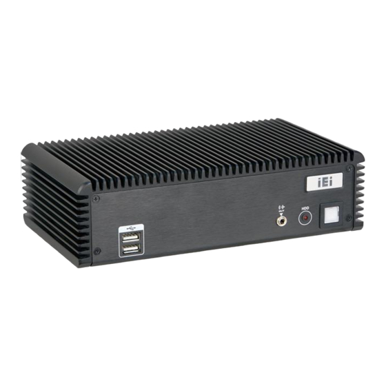
The ECW-281B-BTi combines these features in an aluminum enclosure. Featuring two LAN, four USB, four serial communication ports, digital I/O, as well as audio, and VGA, the ECW-281B-BTi offers system integrators and developers the best selection of robust and high performance computing system platforms. -
Page 19: Rear Panel
ECW-281B-BTi Embedded System 1.5.2 Rear Panel The rear panel of the ECW-281B-BTi provides access to the following external I/O connectors. 1 x 12 V (or 9 V–36 V) DC power input jack 1 x 9 V–36 V DC power input terminal block (WD model only) ... -
Page 20: Bottom Surface
The bottom surface of the ECW-281B-BTi contains the retention screw holes for the VESA MIS-D 100 wall-mount kit and two side mounting brackets. Figure 1-4: Bottom Surface... -
Page 21: Internal Overview
ECW-281B-BTi Embedded System 1.6 Internal Overview The ECW-281B-BTi internal components are listed below: 1 x IEI WAFER-BTi motherboard 1 x IEI IDD-936260A DC-to-DC power converter (WD model only) 1 x IEI iRIS-1010 IPMI module 1 x 2 GB DDR3L SO-DIMM module All the components are accessed by removing the bottom surface. -
Page 22: Technical Specifications
ECW-281B-BTi Embedded System 1.7 Technical Specifications The specifications for the Intel based embedded systems are listed below. ECW-281B-BTi CPU (SoC) Intel® Celeron® processor J1900 (2M cache, 2.42 GHz) System Memory 1 x 204-pin 1066/1333 MHz single-channel DDR3L SO-DIMM slot Preinstalled 2.0 GB DDR3L SDRAM SO-DIMM (system max. 4 GB) Ethernet LAN1: PCIe GbE by Intel®... -
Page 23: Table 1-2: Technical Specifications
ECW-281B-BTi Embedded System Power Supply 9 V – 36 V DC model: Internal DC-to-DC power converter (IDD-936260A) One 9 V–36 V DC power input jack One 9 V–36 V DC power input terminal block 12 V DC model: External power adapter, 90V AC–264V AC @ 47Hz–63Hz, 60 W One 12 V DC power input jack 12V@1.45A (with Intel®... -
Page 24: Power Module Specifications (Optional)
ECW-281B-BTi Embedded System 1.8 Power Module Specifications (Optional) A DC-to-DC power converter module is preinstalled in the WD model to provide 9 V–36 V power input. The specifications for the IDD-936260A are shown in Table 1-3. IDD-936260A 9 V DC–36 V DC... -
Page 25: Dimensions
ECW-281B-BTi Embedded System 1.9 Dimensions The dimensions of the ECW-281B-BTi are listed below and shown in F igure 1-6. 6 5 5 Height: 64.00 mm Width: 229.00 mm Length: 132.00 mm Figure 1-6: Dimensions (mm) Page 11... -
Page 26: Unpacking
ECW-281B-BTi Embedded System Chapter Unpacking Page 12... -
Page 27: Unpacking
Contact the IEI reseller or vendor the ECW-281B-BTi was purchased from or contact an IEI sales representative directly by sending an email to ales@ieiworld.com. The ECW-281B-BTi embedded system is shipped with the following components: Quantity Item Image... -
Page 28: Optional Items
ECW-281B-BTi Embedded System Mounting brackets Screws (M3*5) for mounting brackets Power cord (12 V DC-in model only) 12 V 60 W power adapter with ERP and PSE certificates (12 V DC-in model only) Driver and manual CD One Key Recovery CD Table 2-1: Package List 2.3 Optional Items... -
Page 29: Installation
ECW-281B-BTi Embedded System Chapter Installation Page 15... -
Page 30: Anti-Static Precautions
Electrostatic discharge (ESD) can cause serious damage to electronic components, including the WAFER series motherboard and the power module. (Dry climates are especially susceptible to ESD.) It is therefore critical that whenever the ECW-281B-BTi is opened and any electrical component handled, the following anti-static precautions are strictly adhered to. -
Page 31: High Surface Temperature
Air Circulation: Make sure there is sufficient air circulation when installing the ECW-281B-BTi. The ECW-281B-BTi’s cooling vents must not be obstructed by any objects. Blocking the vents can cause overheating of the ECW-281B-BTi. Leave at least 5 cm of clearance around the ECW-281B-BTi to prevent overheating. ... -
Page 32: Installation Procedure
ECW-281B-BTi Embedded System 3.3 Installation Procedure To properly install the ECW-281B-BTi, the following steps must be followed. Detailed descriptions of these instructions are listed in the sections that follow. Unpacking Step 1: Configure the jumper settings Step 2: Install the SATA hard disk drive (HDD) -
Page 33: Configure The Jumper Settings
3.5.1 Clear CMOS If the ECW-281B-BTi fails to boot due to improper BIOS settings, the clear CMOS button clears the CMOS data and resets the system BIOS information. To do this, push the clear CMOS button for three seconds, then restart the system. The clear CMOS button location is shown in F igure 3-2. -
Page 34: At/Atx Mode Selection
After having done one of the above, save the changes and exit the CMOS Setup menu. 3.5.2 AT/ATX Mode Selection AT or ATX power mode can be used on the ECW-281B-BTi. The selection is made through an AT/ATX switch located on the motherboard (Figure 3-3). -
Page 35: Hard Drive Installation
Table 3-1: AT/ATX Mode Select Switch Settings 3.6 Hard Drive Installation One 2.5” SATA hard drive can be installed in the ECW-281B-BTi. The SATA drive is installed into a hard drive bracket attached on the inside of the bottom panel. To install the hard drive into the system, please follow the steps below. -
Page 36: Figure 3-5: Hdd Retention Screws
ECW-281B-BTi Embedded System Align the retention screw holes in the HDD with those in both sides of the Step 4: bracket. Secure the HDD with the bracket by inserting four retention screws (M3*4) into Step 5: the sides of the bracket ( F igure 3-5). -
Page 37: Figure 3-6: Hdd Installation
ECW-281B-BTi Embedded System Figure 3-6: HDD Installation Connect the SATA cable and the SATA power cable to the SATA connector and Step 8: the SATA power connector on the motherboard. Replace the bottom surface to the bottom panel by reinserting the 10 previously Step 9: removed retention screws. -
Page 38: Full-Size Pcie Mini/Msata Card Installation
ECW-281B-BTi Embedded System 3.7 Full-size PCIe Mini/mSATA Card Installation The PCIe Mini slot allows installation of either a full-size or half-size PCIe Mini card. To install a full-size PCIe Mini card or an mSATA module, please follow the steps below. -
Page 39: Figure 3-9: Removing The Retention Screw
ECW-281B-BTi Embedded System Remove the retention screw. Remove the retention screw as shown in Step 4: Figure 3-9. Figure 3-9: Removing the Retention Screw Insert into the socket at an angle. Line up the notch on the card with the notch Step 5: on the slot. -
Page 40: Half-Size Pcie Mini Card Installation
ECW-281B-BTi Embedded System Figure 3-11: Securing the Full-size PCIe Mini Card NOTE: If an mSATA module is installed in the PCIe Mini slot (CN1), the SATA port 2 (SATA2) will be disabled. Choose either the SATA2 connector or the mSATA module for storage. -
Page 41: Figure 3-12: Pcie Mini Slot Location
ECW-281B-BTi Embedded System Figure 3-12: PCIe Mini Slot Location Remove the retention screw. Remove the retention screw as shown in Step 3: Figure 3-13. Figure 3-13: Removing the Screw Insert into the socket at an angle. Line up the notch on the card with the notch Step 4: on the slot. -
Page 42: Figure 3-14: Inserting The Half-Size Pcie Mini Card Into The Slot At An Angle
ECW-281B-BTi Embedded System Figure 3-14: Inserting the Half-size PCIe Mini Card into the Slot at an Angle Secure the half-size PCIe Mini card. Secure the half-size PCIe Mini card with Step 5: the retention screw previously removed (Figure 3-15). Figure 3-15: Securing the Half-size PCIe Mini Card... -
Page 43: Wireless Lan Module Installation (Optional)
Remove the bottom surface. See Section 3.4. Step 1: Remove the two knockout holes for antenna installation. The two knockout Step 2: holes are located on the rear panel of the ECW-281B-BTi as shown in Figure 3-16. Figure 3-16: Knockout Holes for Wireless Antenna Step 3: Locate the PCIe Mini slot (Figure 3-17). -
Page 44: Figure 3-18: Removing The Retention Screw
ECW-281B-BTi Embedded System Figure 3-18: Removing the Retention Screw Insert into the socket at an angle. Line up the notch on the WLAN module with Step 5: the notch on the slot. Slide the WLAN module into the slot at an angle of about 20º... -
Page 45: Figure 3-20: Securing Wlan Module And Connecting Rf Cables
ECW-281B-BTi Embedded System Figure 3-20: Securing WLAN Module and Connecting RF Cables Remove the nut and washer from the SMA connector at the other end of the Step 8: RF cable. Insert the SMA connector to the antenna connector holes on the rear panel. -
Page 46: Digital I/O Connection
ECW-281B-BTi Embedded System 3.10 Digital I/O Connection The DIO connector on the ECW-281B-BTi is interfaced to GPIO ports on the Super I/O chipset. The DIO has both 4-bit digital inputs and 4-bit digital outputs. The pinouts of the D-sub 9 female connector are listed below. -
Page 47: Mounting The System
NDTR Table 3-4: RS-232 Serial Port Connector Pinouts 3.13 Mounting the System There are two ways to mount the ECW-281B-BTi. The mounting instructions are described below. 3.13.1 Mounting with Mounting Brackets To mount the embedded system onto a wall or some other surface using the two mounting brackets, please follow the steps below. -
Page 48: Mounting With Vesa Mount Kit (Optional)
ECW-281B-BTi Embedded System Drill holes in the intended installation surface. Step 4: Align the mounting holes in the sides of the mounting brackets with the predrilled Step 5: holes in the mounting surface. Insert four retention screws, two in each bracket, to secure the system to the Step 6: wall. -
Page 49: Figure 3-24: Mount The Embedded System
( F igure 3-24). Align the mounting screws on the ECW-281B-BTi bottom panel with the Step 7: mounting holes on the bracket. -
Page 50: Power -O N Procedure
F igure 3-25. 7 6 5 Figure 3-25: Terminal Block Pinouts The chassis ground is connected to the ECW-281B-BTi chassis internally. The cable ground is connected to the ground pin on the input power connector of the power module. Page 36... -
Page 51: Power-On Procedure
Visit the IEI website or contact technical support for the latest updates. All the drivers for the ECW-281B-BTi are on the utility CD that came with the system. The utility CD contains drivers for Windows 7 and Windows 8 operating systems. Please select the corresponding drivers for the system. -
Page 52: Ipmi Setup Procedure
The ECW-281B-BTi features Intelligent Platform Management Interface (IPMI) that helps lower the overall costs of server management by enabling users to maximize IT resources, save time and manage multiple systems. The ECW-281B-BTi supports IPMI 2.0 through the optional iRIS-1010 module. Follow the steps below to setup IPMI. -
Page 53: Bios
ECW-281B-BTi Embedded System Chapter BIOS Page 39... -
Page 54: Introduction
ECW-281B-BTi Embedded System 4.1 Introduction The BIOS is programmed onto the BIOS chip. The BIOS setup program allows changes to certain system settings. This chapter outlines the options that can be changed. NOTE: Some of the BIOS options may vary throughout the life cycle of the product and are subject to change without prior notice. -
Page 55: Getting Help
ECW-281B-BTi Embedded System Function Decrease the numeric value or make changes Page up Move to the next page Page down Move to the previous page Main Menu – Quit and do not save changes into CMOS Status Page Setup Menu and Option Page Setup Menu --... -
Page 56: Main
ECW-281B-BTi Embedded System Save & Exit – Selects exit options and loads default settings Server Mgmt – Changes the server management configuration. The following sections completely describe the configuration options found in the menu items at the top of the BIOS screen and listed above. -
Page 57: Advanced
ECW-281B-BTi Embedded System The Main menu has two user configurable fields: System Date [xx/xx/xx] Use the System Date option to set the system date. Manually enter the day, month and year. System Time [xx:xx:xx] Use the System Time option to set the system time. Manually enter the hours, minutes and seconds. -
Page 58: Acpi Settings
ECW-281B-BTi Embedded System Aptio Setup Utility – Copyright (C) 2013 American Megatrends, Inc. Main Advanced Chipset Security Boot Save & Exit Server Mgmt > ACPI Settings System ACPI Parameters > Super IO Configuration > Hardware Monitor > RTC Wake Settings >... -
Page 59: Super Io Configuration
ECW-281B-BTi Embedded System ACPI Sleep State [S3 (Suspend to RAM)] Use the ACPI Sleep State option to specify the sleep state the system enters when it is not being used. The suspend function is disabled. Suspend Disabled EFAULT ... -
Page 60: Serial Port N Configuration
ECW-281B-BTi Embedded System 4.3.2.1 Serial Port n Configuration Use the Serial Port n Configuration menu ( B IOS Menu 5) to configure the serial port n. Aptio Setup Utility – Copyright (C) 2013 American Megatrends, Inc. Advanced Serial Port n Configuration... - Page 61 ECW-281B-BTi Embedded System Serial Port I/O port address is 3F8h and the interrupt IO=3F8h; address is IRQ3, 4, 5, 6, 7, 9, 10, 11, 12 IRQ=3, 5, 6, 7, 9, 10, 11, 12 Serial Port I/O port address is 2F8h and the interrupt IO=2F8h;...
-
Page 62: Change Settings [Auto]
ECW-281B-BTi Embedded System Serial Port I/O port address is 2F8h and the interrupt IO=2F8h; address is IRQ3 IRQ=3 Serial Port I/O port address is 3F8h and the interrupt IO=3F8h; address is IRQ3, 4, 5, 6, 7, 9, 10, 11, 12... - Page 63 ECW-281B-BTi Embedded System The serial port IO port address and interrupt address Auto EFAULT are automatically detected. Serial Port I/O port address is 3E8h and the interrupt IO=3E8h; address is IRQ7 IRQ=7 Serial Port I/O port address is 3F8h and the interrupt IO=3F8h;...
- Page 64 ECW-281B-BTi Embedded System 4.3.2.1.4 Serial Port 4 Configuration Serial Port [Enabled] Use the Serial Port option to enable or disable the serial port. Disable the serial port Disabled Enable the serial port Enabled EFAULT Change Settings [Auto] Use the Change Settings option to change the serial port IO port address and interrupt address.
-
Page 65: Hardware Monitor
ECW-281B-BTi Embedded System Serial Port I/O port address is 2F0h and the interrupt IO=2F0h; address is IRQ3, 4, 5, 6, 7, 9, 10, 11, 12 IRQ=3, 5, 6, 7, 9, 10, 11, 12 Serial Port I/O port address is 2E0h and the interrupt IO=2E0h;... -
Page 66: Smart Fan Function
ECW-281B-BTi Embedded System CPU Temperature System Temperature Fan speed: CPU fan speed System fan speed 4.3.3.1 Smart Fan Function Use the Smart Fan Function menu ( B IOS Menu 7) to configure the smart fan temperature and speed settings. -
Page 67: Start Pwm
ECW-281B-BTi Embedded System Temperature of Off Use the + or – key to change the Temperature of Off value or enter a decimal number between 1 and 127. If the CPU temperature is lower than the value set in this option, the fan speed will change to the lowest speed. -
Page 68: Rtc Wake Settings
ECW-281B-BTi Embedded System 4.3.4 RTC Wake Settings The RTC Wake Settings menu (BIOS Menu 8) enables the system to wake at the specified time. Aptio Setup Utility – Copyright (C) 2013 American Megatrends, Inc. Advanced Wake system with Fixed Time... -
Page 69: Serial Port Console Redirection
ECW-281B-BTi Embedded System Wake up minute Wake up second After setting the alarm, the computer turns itself on from a suspend state when the alarm goes off. 4.3.5 Serial Port Console Redirection The Serial Port Console Redirection menu ( B IOS Menu 9) allows the console redirection options to be configured. -
Page 70: Console Redirection Settings
ECW-281B-BTi Embedded System 4.3.5.1 Console Redirection Settings Use the Console Redirection Settings menu ( B IOS Menu 10) to configure console redirection settings of the specified serial port. This menu appears only when the Console Redirection is enabled. Aptio Setup Utility – Copyright (C) 2013 American Megatrends, Inc. - Page 71 ECW-281B-BTi Embedded System Sets the serial port transmission speed at 9600. 9600 Sets the serial port transmission speed at 19200. 19200 Sets the serial port transmission speed at 39400. 38400 Sets the serial port transmission speed at 57600.
-
Page 72: Iei Feature
ECW-281B-BTi Embedded System Sets the number of stop bits at 1. EFAULT Sets the number of stop bits at 2. 4.3.6 iEi Feature Use the iEi Feature menu (BIOS Menu 11) to configure One Key Recovery function. Aptio Setup Utility – Copyright (C) 2013 American Megatrends, Inc. -
Page 73: Cpu Configuration
ECW-281B-BTi Embedded System 4.3.7 CPU Configuration Use the CPU Configuration menu ( B IOS Menu 12) to view detailed CPU specifications and configure the CPU. Aptio Setup Utility – Copyright (C) 2013 American Megatrends, Inc. Advanced CPU Configuration When enabled, a VMM can utilize the additional Intel(R) Celeron(R) CPU J1900 @ 1.99GHz... -
Page 74: Eist [Enabled]
ECW-281B-BTi Embedded System L3 Cache: Lists the amount of storage space on the L3 cache. CPU Speed: Lists the CPU speed. 64-bit: Indicates if 64-bit system is supported by the CPU. Intel Virtualization Technology [Enabled] Use the Intel Virtualization Technology option to enable or disable virtualization on the system. -
Page 75: Ide Configuration
ECW-281B-BTi Embedded System 4.3.8 IDE Configuration Use the IDE Configuration menu ( B IOS Menu 13) to change and/or set the configuration of the SATA devices installed in the system. Aptio Setup Utility – Copyright (C) 2013 American Megatrends, Inc. -
Page 76: Usb Configuration
ECW-281B-BTi Embedded System SATA Port 1/0 HotPlug [Disabled] Use the SATA Port 1/0 HotPlug option to enable or disable the hot plug function of the SATA port. Enables the hot plug function of the SATA port. Enabled ... -
Page 77: Chipset
ECW-281B-BTi Embedded System Legacy USB Support [Enabled] Use the Legacy USB Support BIOS option to enable USB mouse and USB keyboard support. Normally if this option is not enabled, any attached USB mouse or USB keyboard does not become available until a USB compatible operating system is fully booted with all USB drivers loaded. -
Page 78: North Bridge
ECW-281B-BTi Embedded System Aptio Setup Utility – Copyright (C) 2013 American Megatrends, Inc. Main Advanced Chipset Security Boot Save & Exit Server Mgmt > North Bridge North Bridge Parameters > South Bridge --------------------- : Select Screen : Select Item Enter: Select +/-: Change Opt. -
Page 79: Intel Igd Configuration
ECW-281B-BTi Embedded System 4.4.1.1 Intel IGD Configuration Use the Intel IGD Configuration submenu (BIOS Menu 17) to configure the graphics settings. Aptio Setup Utility – Copyright (C) 2013 American Megatrends, Inc. Chipset DVMT Pre-Allocated [256M] Select DVMT 5.0 DVMT Total Gfx Mem... -
Page 80: South Bridge
ECW-281B-BTi Embedded System DVMT Total Gfx Mem [Max] Use the DVMT Total Gfx Mem option to specify the maximum amount of memory that can be allocated as graphics memory. Configuration options are listed below. 128MB 256MB ... -
Page 81: Pci Express Configuration
ECW-281B-BTi Embedded System Restore AC Power Loss [Last State] Use the Restore AC Power BIOS option to specify what state the system returns to if there is a sudden loss of power to the system. The system remains turned off Power Off ... -
Page 82: Security
ECW-281B-BTi Embedded System PCI Express Port n [Enabled] Use the PCI Express Port n BIOS option to enable or disable the PCI Express slot. Enable the PCI Express slot. Enabled EFAULT Disable the PCI Express slot. Disabled ... -
Page 83: Boot
ECW-281B-BTi Embedded System User Password Use the User Password to set or change a user password. 4.6 Boot Use the Boot menu ( B IOS Menu 21) to configure system boot options. Aptio Setup Utility – Copyright (C) 2013 American Megatrends, Inc. -
Page 84: Option Rom Messages [Keep Current]
ECW-281B-BTi Embedded System Does not enable the keyboard Number Lock automatically. To use the 10-keys on the keyboard, press the Number Lock key located on the upper left-hand corner of the 10-key pad. The Number Lock LED on the keyboard lights up when the Number Lock is engaged. -
Page 85: Save & Exit
ECW-281B-BTi Embedded System Launch PXE OpROM [Disabled] Use the Launch PXE OpROM option to enable or disable boot option for legacy network devices. Ignore all PXE Option ROMs Disabled EFAULT Load PXE Option ROMs Enabled 4.7 Save & Exit Use the Save &... -
Page 86: Server Mgmt
ECW-281B-BTi Embedded System Restore Defaults Use the Restore Defaults option to load the optimal default values for each of the parameters on the Setup menus. F3 key can be used for this operation. Save as User Defaults Use the Save as User Defaults option to save the changes done so far as user defaults. -
Page 87: System Event Log
ECW-281B-BTi Embedded System 4.8.1 System Event Log Use the System Event Log menu (BIOS Menu 24) to configure system event log options. Aptio Setup Utility – Copyright (C) 2013 American Megatrends, Inc. Server Mgmt Enabling/Disabling Options Change this to enable or... -
Page 88: Bmc Network Configuration
ECW-281B-BTi Embedded System Erase SEL on every reset Yes, On every reset When SEL is Full [Do Nothing] Use the When SEL is Full option to select an option for reaction to a full SEL. Do nothing when SEL is full... - Page 89 ECW-281B-BTi Embedded System Configuration Address source [Unspecified] Use the Configuration Address source to configure LAN channel parameters statically or dynamically (by BIOS or BMC). BMC network parameters will not be Unspecified EFAULT modified during BIOS phase. Select to modify the following BMC...
-
Page 90: Troubleshooting And Maintenance
ECW-281B-BTi Embedded System Chapter Troubleshooting and Maintenance Page 76... -
Page 91: Ecw-281B-Bti System Maintenance Overview
Failure to follow these instructions may lead to personal injury and system damage. To preserve the working integrity of the ECW-281B-BTi embedded system, the system must be properly maintained. If embedded system components need replacement, the proper maintenance procedures must be followed to ensure the system can continue to operate normally. -
Page 92: The System Doesn't Boot Up
ECW-281B-BTi Embedded System Check that the power cable connector is properly plugged into the power source. Step 2: Make sure the power button is turned on. Step 3: Plug the system into a monitor and check to see if anything appears on the Step 4: screen. -
Page 93: More Troubleshooting
If all troubleshooting measures have been taken and the system still fails to start, contact the IEI reseller or vendor you purchased the ECW-281B-BTi from or contact an IEI sales representative directly. To contact an IEI sales representative, please send an email to ales@ieiworld.com. -
Page 94: So-Dimm Replacement
To replace a SO-DIMM memory module into a SO-DIMM socket, please follow the steps below. Remove the bottom surface panel. Place the ECW-281B-BTi on an anti-static Step 1: pad with the bottom panel facing up and the bottom surface removed (see Section 3 .4). -
Page 95: Figure 5-2: So-Dimm Installation
ECW-281B-BTi Embedded System Insert the SO-DIMM. Push the SO-DIMM chip into the socket at an angle Step 5: F igure 5-2). 8 6 6 Figure 5-2: SO-DIMM Installation Open the SO-DIMM socket arms. Gently pull the arms of the SO-DIMM socket... -
Page 96: System Components
ECW-281B-BTi Embedded System Chapter System Components Page 82... -
Page 97: Embedded System Motherboard
The ECW-281B-BTi models have a WAFER-BT-i1 motherboard installed in the system. The following sections describe the relevant connectors and jumpers on the motherboard. 6.1.1 WAFER-BT-i1 Motherboard Overview The locations of the WAFER-BT-i1 jumpers and connectors used on the ECW-281B-BTi are shown in F igure 6-1 below. -
Page 98: Peripheral Interface Connectors
6.2.1 Peripheral Interface Connectors T able 6-1 shows a list of the peripheral interface connectors on the WAFER-BT-i1 that are 6 5 6 used for the ECW-281B-BTi. Detailed descriptions of these connectors can be found in Section 6 .3. 6 5 6... -
Page 99: Internal Peripheral Connectors
ECW-281B-BTi Embedded System 6.3 Internal Peripheral Connectors Internal peripheral connectors are found on the motherboard and are only accessible when the motherboard is outside of the chassis. This section has complete descriptions of the internal, peripheral connectors on the WAFER-BT-i1 that are used for the ECW-281B-BTi. -
Page 100: Battery Connector
ECW-281B-BTi Embedded System Figure 6-3: Audio Connector Location PIN NO. DESCRIPTION PIN NO. DESCRIPTION LINE_OUTR LINEIN_R Analog_GND Analog_GND LINE_OUTL LINEIN_L Analog_GND Analog_GND LMIC1-R LMIC1-L Table 6-3: Audio Connector Pinouts 6.3.3 Battery Connector The battery connector is connected to the system battery. The battery provides power to the system clock to retain the time when power is turned off. -
Page 101: Buzzer Connector
ECW-281B-BTi Embedded System PIN NO. DESCRIPTION PIN NO. DESCRIPTION VBATT Table 6-4: Battery Connector Pinouts 6.3.4 Buzzer Connector The buzzer connector is connected to the buzzer. Figure 6-5: Buzzer Connector Location PIN NO. DESCRIPTION PIN NO. DESCRIPTION Buzzer + Buzzer - Table 6-5: Buzzer Connector Pinouts 6.3.5 DDR3L SO-DIMM Slot... -
Page 102: Digital I/O Connector
ECW-281B-BTi Embedded System Figure 6-6: DDR3L SO-DIMM Slot Location 6.3.6 Digital I/O Connector The digital I/O connector provides programmable input and output for external devices. The digital I/O provides 4-bit output and 4-bit input. Figure 6-7: Digital I/O Connector Location PIN NO. -
Page 103: Front Panel Connector
ECW-281B-BTi Embedded System 6.3.7 Front Panel Connector The front panel connector connects to the indicator LEDs on the system front panel. Figure 6-8: Front Panel Connector Location PIN NO. DESCRIPTION PIN NO. DESCRIPTION PWR_LED+ PWR_LED- HDD_LED+ HDD_LED- Table 6-7: Front Panel Connector Pinouts 6.3.8 iRIS-1010 module slot... -
Page 104: Pcie Mini Card/Msata Slot
The iRIS-1010 module slot is designed to install the IEI iRIS-1010 IPMI 2.0 module. DO NOT install other modules into the iRIS-1010 module slot. Doing so may cause damage to the ECW-281B-BTi. 6.3.9 PCIe Mini Card/mSATA Slot The PCIe Mini card slot is for installing a PCIe Mini expansion card or an mSATA module. -
Page 105: Reset Button Connector
ECW-281B-BTi Embedded System Figure 6-11: Power Button Connector Location PIN NO. DESCRIPTION PWRBTN_SW# Table 6-8: Power Button Connector Pinouts 6.3.11 Reset Button Connector The reset button connector is connected to a reset switch on the system chassis to enable users to reboot the system when the system is turned on. -
Page 106: Serial Port Connectors
ECW-281B-BTi Embedded System PIN NO. DESCRIPTION PM_SYSRST_R# Table 6-9: Reset Button Connector Pinouts 6.3.12 RS-232 Serial Port Connectors The serial connector provides RS-232 connection. Figure 6-13: RS-232 Serial Port Connectors Locations PIN NO. DESCRIPTION PIN NO. DESCRIPTION Table 6-10: RS-232 Serial Port Connector Pinouts... -
Page 107: Rs-422/485 Serial Port Connector
ECW-281B-BTi Embedded System 6.3.13 RS-422/485 Serial Port Connector This connector provides RS-422 or RS-485 communications. Figure 6-14: RS-422/485 Connector Location PIN NO. DESCRIPTION PIN NO. DESCRIPTION RXD422- RXD422+ TXD422+/TXD485+ TXD422-/TXD485- Table 6-11: RS-422/485 Connector Pinouts Use the optional RS-422/485 cable to connect to a serial device. The pinouts of the DB-9 connector are listed below. -
Page 108: Sata 3Gb/S Drive Connector
ECW-281B-BTi Embedded System 6.3.14 SATA 3Gb/s Drive Connector The SATA 3Gb/s drive connector is connected to a SATA 3Gb/s drive. The SATA 3Gb/s drive transfers data at speeds as high as 3Gb/s. NOTE: If an HDD is connected to the SATA port 2 (SATA2), an mSATA module will not be supported by the PCIe Mini slot (CN1). -
Page 109: Usb Connectors
ECW-281B-BTi Embedded System Figure 6-16: SATA Power Connector Location PIN NO. DESCRIPTION Table 6-13: SATA Power Connector Pinouts 6.3.16 USB Connectors The USB connectors provide four USB 2.0 ports by dual-port USB cable. Figure 6-17: USB Connectors Locations PIN NO. -
Page 110: External Peripheral Interface Connector Panel
ECW-281B-BTi Embedded System 6.4 External Peripheral Interface Connector Panel Figure 6-18 shows the WAFER-BT-i1 external peripheral interface connector (EPIC) panel. The EPIC panel consists of the following: 2 x LAN connectors 1 x USB 3.0 connector 1 x USB 2.0 connector ... -
Page 111: Serial Port Connector
Table 6-17: RS-232 Serial Port Connector Pinouts 6.4.3 USB Connectors The ECW-281B-BTi has one external USB 2.0 port and one external USB 3.0 port. The USB connector can be connected to a USB device. The pinouts of USB 2.0 port & USB 3.0 connectors are shown below. -
Page 112: Vga Connector
ECW-281B-BTi Embedded System PIN NO. DESCRIPTION PIN NO. DESCRIPTION USB3P0_RXDN1 USB3P0_RXDP1 USB3P0_TXDN1 USB3P0_TXDP1 Table 6-18: USB 3.0 Port Pinouts PIN NO. DESCRIPTION PIN NO. DESCRIPTION -DATA_USB3 -DATA_USB4 Table 6-19: USB 2.0 Port Pinouts 6.4.4 VGA Connector The VGA port connects to a monitor that accepts a standard VGA input. -
Page 113: A Regulatory Compliance
ECW-281B-BTi Embedded System Appendix Regulatory Compliance Page 99... - Page 114 ECW-281B-BTi Embedded System DECLARATION OF CONFORMITY This equipment is in conformity with the following EU directives: EMC Directive 2004/108/EC Low-Voltage Directive 2006/95/EC RoHS II Directive 2011/65/EU Ecodesign Directive 2009/125/EC If the user modifies and/or install other devices in the equipment, the CE conformity declaration may no longer apply.
- Page 115 ECW-281B-BTi Embedded System Español [Spanish] IEI Integration Corp declara que el equipo cumple con los requisitos esenciales y cualesquiera otras disposiciones aplicables o exigibles de la Directiva 1999/5/CE. Ελληνική [Greek] IEI Integration Corp ΔΗΛΩΝΕΙ ΟΤΙ ΕΞΟΠΛΙΣΜΟΣ ΣΥΜΜΟΡΦΩΝΕΤΑΙ ΠΡΟΣ ΤΙΣ ΟΥΣΙΩΔΕΙΣ ΑΠΑΙΤΗΣΕΙΣ ΚΑΙ ΤΙΣ ΛΟΙΠΕΣ ΣΧΕΤΙΚΕΣ ΔΙΑΤΑΞΕΙΣ ΤΗΣ ΟΔΗΓΙΑΣ...
- Page 116 ECW-281B-BTi Embedded System Româna [Romanian] IEI Integration Corp declară că acest echipament este in conformitate cu cerinţele esenţiale şi cu celelalte prevederi relevante ale Directivei 1999/5/CE. Slovensko [Slovenian] IEI Integration Corp izjavlja, da je ta opreme v skladu z bistvenimi zahtevami in ostalimi relevantnimi določili direktive 1999/5/ES.
- Page 117 ECW-281B-BTi Embedded System FCC WARNING This equipment complies with Part 15 of the FCC Rules. Operation is subject to the following two conditions: This device may not cause harmful interference, and This device must accept any interference received, including interference ...
-
Page 118: B Safety Precautions
ECW-281B-BTi Embedded System Appendix Safety Precautions Page 104... -
Page 119: Safety Precautions
Do not apply voltage levels that exceed the specified voltage range. Doing so may cause fire and/or an electrical shock. Electric shocks can occur if the ECW-281B-BTi chassis is opened when the ECW-281B-BTi is running. Do not drop or insert any objects into the ventilation openings of the ECW-281B-BTi. -
Page 120: Anti-Static Precautions
Electrostatic discharge (ESD) can cause serious damage to electronic components, including the ECW-281B-BTi. Dry climates are especially susceptible to ESD. It is therefore critical that whenever the ECW-281B-BTi is opened and any of the electrical components are handled, the following anti-static precautions are strictly adhered to. -
Page 121: Product Disposal
Please follow the national guidelines for electrical and electronic product disposal. B.2 Maintenance and Cleaning Precautions When maintaining or cleaning the ECW-281B-BTi, please follow the guidelines below. B.2.1 Maintenance and Cleaning Prior to cleaning any part or component of the ECW-281B-BTi, please read the details below. Page 107... -
Page 122: Cleaning Tools
Some components in the ECW-281B-BTi may only be cleaned using a product specifically designed for the purpose. In such case, the product will be explicitly mentioned in the cleaning tips. Below is a list of items to use when cleaning the ECW-281B-BTi. ... -
Page 123: Cbios Menu Options
ECW-281B-BTi Embedded System Appendix BIOS Menu Options Page 109... -
Page 124: Bios Configuration Options
ECW-281B-BTi Embedded System C.1 BIOS Configuration Options Below is a list of BIOS configuration options described in Chapter 4. System Date [xx/xx/xx] ......................43 System Time [xx:xx:xx] .......................43 ACPI Sleep State [S3 (Suspend to RAM)]................45 Serial Port [Enabled]......................46 ... - Page 125 ECW-281B-BTi Embedded System Legacy USB Support [Enabled]..................63 DVMT Pre-Allocated [256M] ....................65 DVMT Total Gfx Mem [Max]....................66 Primary IGFX Boot Display [VBIOS Default] ..............66 Restore AC Power Loss [Last State] .................67 Audio Controller [Enabled] ....................67 ...
-
Page 126: D Digital I/O Interface
ECW-281B-BTi Embedded System Appendix Digital I/O Interface Page 112... -
Page 127: Introduction
ECW-281B-BTi Embedded System D.1 Introduction The DIO connector on the ECW-281B-BTi is interfaced to GPIO ports on the Super I/O chipset. The DIO has both 4-bit digital inputs and 4-bit digital outputs. The digital inputs and digital outputs are generally control signals that control the on/off circuit of external devices or TTL devices. -
Page 128: Assembly Language Sample
ECW-281B-BTi Embedded System D.2 Assembly Language Sample 1 AX, 6F08H ;setting the digital port as input AL low byte = value AH – 6FH Sub-function: AL – 9 :Set the digital port as OUTPUT :Digital I/O input value D.3 Assembly Language Sample 2 AX, 6F09H ;setting the digital port as output... -
Page 129: E Watchdog Timer
ECW-281B-BTi Embedded System Appendix Watchdog Timer Page 115... - Page 130 ECW-281B-BTi Embedded System NOTE: The following discussion applies to DOS environment. IEI support is contacted or the IEI website visited for specific drivers for more sophisticated operating systems, e.g., Windows and Linux. The Watchdog Timer is provided to ensure that standalone systems can always recover from catastrophic conditions that cause the CPU to crash.
-
Page 131: Example Program
ECW-281B-BTi Embedded System NOTE: When exiting a program it is necessary to disable the Watchdog Timer, otherwise the system resets. Example program: ; INITIAL TIMER PERIOD COUNTER W_LOOP: AX, 6F02H ;setting the time-out value BL, 30 ;time-out value is 48 seconds ;... -
Page 132: F Hazardous Materials Disclosure
ECW-281B-BTi Embedded System Appendix Hazardous Materials Disclosure Page 118... -
Page 133: Hazardous Materials Disclosure Table For Ipb Products Certified As
ECW-281B-BTi Embedded System F.1 Hazardous Materials Disclosure Table for IPB Products Certified as RoHS Compliant Under 2002/95/EC Without Mercury The details provided in this appendix are to ensure that the product is compliant with the Peoples Republic of China (China) RoHS standards. The table below acknowledges the presences of small quantities of certain materials in the product, and is applicable to China RoHS only. - Page 134 ECW-281B-BTi Embedded System Part Name Toxic or Hazardous Substances and Elements Lead Mercury Cadmium Hexavalent Polybrominated Polybrominated (Pb) (Hg) (Cd) Chromium Biphenyls Diphenyl (CR(VI)) (PBB) Ethers (PBDE) Housing Display Printed Circuit Board Metal Fasteners Cable Assembly Fan Assembly Power Supply...
- Page 135 ECW-281B-BTi Embedded System 此附件旨在确保本产品符合中国 RoHS 标准。以下表格标示此产品中某有毒物质的含量符 合中国 RoHS 标准规定的限量要求。 本产品上会附有”环境友好使用期限”的标签,此期限是估算这些物质”不会有泄漏或突变”的 年限。本产品可能包含有较短的环境友好使用期限的可替换元件,像是电池或灯管,这些元 件将会单独标示出来。 部件名称 有毒有害物质或元素 铅 汞 镉 六价铬 多溴联苯 多溴二苯 醚 (Pb) (Hg) (Cd) (CR(VI)) (PBB) (PBDE) 壳体 显示 印刷电路板 金属螺帽 电缆组装 风扇组装 电力供应组装 电池 O: 表示该有毒有害物质在该部件所有物质材料中的含量均在 SJ/T11363-2006 标准规定的限量要求以下。 X: 表示该有毒有害物质至少在该部件的某一均质材料中的含量超出 SJ/T11363-2006 标准规定的限量要求。...
Need help?
Do you have a question about the ECW-281B-BTi and is the answer not in the manual?
Questions and answers