Table of Contents
Advertisement
Quick Links
Advertisement
Table of Contents

Related Manuals for IEI Technology IDS-310AI


Summary of Contents for IEI Technology IDS-310AI
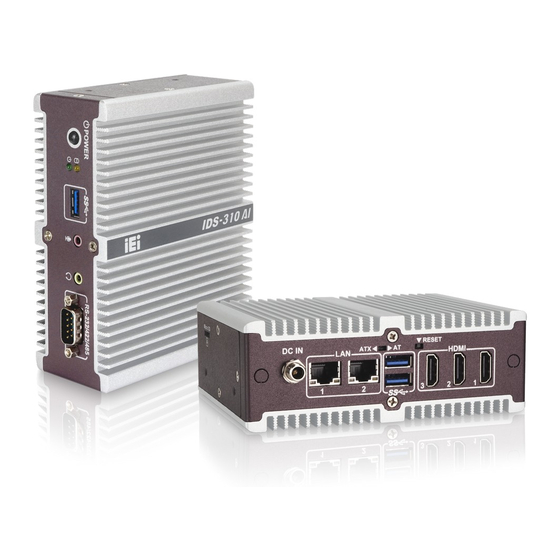
- Page 1 IDS-310AI Embedded System System MODEL: IDS-310AI Embedded System with Intel® Celeron® J3455 Processor, Three HDMI, 128 GB SATA DOM, USB 3.2 Gen 1, Dual GbE, VPU Accelerator, RS-232/422/485 and RoHS Compliant User Manual Page I Rev. 1.00 – September 28, 2020...
- Page 2 IDS-310AI Embedded System Revision Date Version Changes September 28, 2020 1.00 Initial release Page II...
- Page 3 IDS-310AI Embedded System Copyright COPYRIGHT NOTICE The information in this document is subject to change without prior notice in order to improve reliability, design and function and does not represent a commitment on the part of the manufacturer. In no event will the manufacturer be liable for direct, indirect, special, incidental, or consequential damages arising out of the use or inability to use the product or documentation, even if advised of the possibility of such damages.
- Page 4 IDS-310AI Embedded System Safety Instructions Warning! Read the user manual before connecting the system to the power source. Vorsicht! Bitte lesen Sie die Bedienungsanleitung, bevor Sie das System an eine Stromquelle anschließen. Attention! Avant de brancher le système à la source d'alimentation, consultez le mode d'emploi.
- Page 5 IDS-310AI Embedded System Warning! Use only the adapter and power cord approved for this system. Use of another type of adapter may risk fire or explosion. Please refer to the user manual for the power adapter specifications. Vorsicht! Nur zugelassene Netzteile und Netzkabel dürfen verwendet werden. Die Benutzung von anderen Netzteilen kann einen Brand oder eine Explosion zur Folge haben.
- Page 6 IDS-310AI Embedded System Manual Conventions WARNING Warnings appear where overlooked details may cause damage to the equipment or result in personal injury. Warnings should be taken seriously. CAUTION Cautionary messages should be heeded to help reduce the chance of losing data or damaging the product.
-
Page 7: Table Of Contents
IDS-310AI Embedded System Table of Contents 1 INTRODUCTION ......................1 1.1 O ........................2 VERVIEW 1.2 F ........................2 EATURES 1.3 I/O P ......................... 3 ANELS 1.4 S ........................ 4 ANEL 1.5 T ..................4 ECHNICAL PECIFICATIONS 1.6 D ....................... 6 IMENSIONS 2 UNPACKING ......................... - Page 8 IDS-310AI Embedded System 3.10 C CMOS ......................26 LEAR 3.11 F .............. 27 LASH ESCRIPTOR ECURITY VERRIDE 4 BIOS ..........................28 4.1 I ......................29 NTRODUCTION 4.1.1 Starting Setup ....................29 4.1.2 Using Setup ...................... 29 4.1.3 Getting Help ..................... 30 4.1.4 BIOS Menu Bar ....................
- Page 9 IDS-310AI Embedded System 5 MAINTENANCE ......................62 5.1 S ................. 63 YSTEM AINTENANCE VERVIEW 5.2 C ..............63 OMPONENT EPLACEMENT ROCEDURE 5.2.1 SO-DIMM Replacement ................... 64 6 INTERFACE CONNECTORS ................... 66 6.1 P ..............67 ERIPHERAL NTERFACE ONNECTORS 6.2 I ..............
- Page 10 IDS-310AI Embedded System E.1 PEI B ...................... 92 ODES E.2 DXE B ....................92 ODES F HAZARDOUS MATERIALS DISCLOSURE ............93 F.1 R HS II D (2015/863/EU) ................ 94 IRECTIVE F.2 C HS ......................95 HINA Page X...
- Page 11 IDS-310AI Embedded System List of Figures Figure 1-1: IDS-310AI Embedded System ..................2 Figure 1-2: I/O Panel - Front ......................3 Figure 1-3: I/O Panel - Rear ......................3 Figure 1-4: Side Panel ........................4 Figure 1-5: Dimensions with Wall Mount Brackets (mm) ............6 Figure 3-1: Bottom Surface Retention Screws ................
- Page 12 IDS-310AI Embedded System List of Tables Table 1-1: Technical Specifications ....................5 Table 2-1: Package List ........................9 Table 2-2: Optional Items ....................... 9 Table 3-1: LAN Connector Pinouts ..................... 20 Table 3-2:: Ethernet Connector LEDs ..................20 Table 3-3: HDMI Connector Pinouts ................... 21 Table 3-4: Power Connector Pinouts ..................
- Page 13 IDS-310AI Embedded System List of BIOS Menus BIOS Menu 1: Main ........................31 BIOS Menu 2: Advanced ......................32 BIOS Menu 3: Trusted Computing ....................33 BIOS Menu 4: ACPI Settings ....................... 34 BIOS Menu 5: F81803 Super IO Configuration ................35 BIOS Menu 6: Serial Port 1 Configuration Menu ...............
-
Page 15: Introduction
IDS-310AI Embedded System Chapter Introduction Page 1... -
Page 16: Overview
The IDS-310AI is a fanless embedded system with Intel Celeron J3455 SoC. The IDS-310AI is preinstalled with 8 GB of DDR3L SO-DIMM. Storage in the system is supported by the pre-installed 128 GB SATA DOM and the microSD slot on the side panel. -
Page 17: I/O Panels
Support audio line-out and mic-in RoHS compliant design 1.3 I/O Panels The I/O panels of the IDS-310AI are shown in Figure 1-2 and Figure 1-3. Figure 1-2: I/O Panel - Front Figure 1-3: I/O Panel - Rear Page 3... -
Page 18: Side Panel
IDS-310AI Embedded System 1.4 Side Panel The side panel of the IDS-310AI has one microSD slot. Figure 1-4: Side Panel 1.5 Technical Specifications The specifications for the IDS-310AI are listed below. IDS-310AI Intel® Celeron® J3455 (up to 2.3 GHz, quad-core, TDP 10 W) -
Page 19: Table 1-1: Technical Specifications
IDS-310AI Embedded System Accelerator Mustang-MPCIE-MX2 VPU accelerator card pre-installed 1 x M.2 A-key 2230 slot (PCIe x1, USB 2.0) for optional Wi-Fi Expansion Slot module Wireless Optional Wi-Fi 802.11a/b/g/n/ac 1 x Power button 1 x Power LED (green) Buttons and Indicators... -
Page 20: Dimensions
IDS-310AI Embedded System 1.6 Dimensions The physical dimensions of the IDS-310AI with its mounting kit are shown below. Figure 1-5: Dimensions with Wall Mount Brackets (mm) Page 6... -
Page 21: Unpacking
IDS-310AI Embedded System Chapter Unpacking Page 7... -
Page 22: Unpacking
If any of the components listed in the checklist below are missing, do not proceed with the installation. Contact the IEI reseller or vendor the IDS-310AI was purchased from or contact an IEI sales representative directly by sending an email to sales@ieiworld.com. -
Page 23: Optional Items
IDS-310AI Embedded System Power adapter (36 W) Power cord Wall mount bracket Screws (M3*5) for wall mount Table 2-1: Package List 2.3 Optional Items The following are optional component(s) which may be separately purchased: Wi-Fi module* (P/N: 27319-000009-RS) External antenna... -
Page 24: Installation
IDS-310AI Embedded System Chapter Installation Page 10... -
Page 25: Anti-Static Precautions
IDS-310AI and severe injury to the user. Electrostatic discharge (ESD) can cause serious damage to electronic components, including the IDS-310AI. Dry climates are especially susceptible to ESD. It is therefore critical that whenever the IDS-310AI or any other electrical component is handled, the following anti-static precautions are strictly adhered to. -
Page 26: High Surface Temperature
IDS-310AI Embedded System Air Circulation: Make sure there is sufficient air circulation when installing the IDS-310AI. The IDS-310AI must not be obstructed by any objects. Leave at least 5 cm of clearance around the IDS-310AI to prevent overheating. ... -
Page 27: Figure 3-1: Bottom Surface Retention Screws
IDS-310AI Embedded System Figure 3-1: Bottom Surface Retention Screws Step 2: Gently lift and remove the bottom surface from the IDS-310AI. Step 0: Figure 3-2: Bottom Surface Removal Page 13... -
Page 28: Wireless Lan Module Installation (Optional)
Remove the bottom surface. See Section 3.3. Step 2: Remove the two knockouts for antenna installation. The two knockouts are located on the rear panel of the IDS-310AI as shown in Figure 3-3. Figure 3-3: Knockouts for Wireless Antenna Step 3: Remove the pre-installed Mustang-MPCIE-MX2 accelerator card to access the M.2 slot. -
Page 29: Figure 3-5: M.2 A-Key Slot Location
IDS-310AI Embedded System Step 4: Locate the M.2 A-key slot on the motherboard (Figure 3-5). Remove the M.2 module screw. Figure 3-5: M.2 A-key Slot Location Step 5: Line up the notch on the WLAN module with the notch on the slot. Slide the WLAN module into the slot at an angle of about 20º... -
Page 30: Figure 3-7: Securing The Wlan Module
IDS-310AI Embedded System Figure 3-7: Securing the WLAN Module Step 7: Connect the two RF cables to the antenna connectors on the WLAN module (Figure 3-8). Figure 3-8: Connecting RF Cables Step 8: Remove the nut and washer from the SMA connector at the other end of the RF cable. -
Page 31: At/Atx Power Mode Selection
Figure 3-9: Securing SMA Connector and External Antenna Installation 3.5 AT/ATX Power Mode Selection AT and ATX power modes can both be used on the IDS-310AI. The selection is made through an AT/ATX switch on the rear panel (Figure 1-3). -
Page 32: Mounting The System
IDS-310AI Embedded System 3.6 Mounting the System To mount the IDS-310AI onto a wall or some other surface using the two mounting brackets, please follow the steps below. Step 1: Align the two retention screw holes in each bracket with the retention screw holes on the side panels. -
Page 33: External Peripheral Interface Connection
IDS-310AI Embedded System 3.7 External Peripheral Interface Connection The following external peripheral devices can be connected to the external peripheral interface connectors. Audio devices RJ-45 Ethernet cable connectors HDMI monitors Serial port devices USB devices The locations of the external peripheral interface connectors are shown in Figure 3-12. -
Page 34: Lan Connectors
IDS-310AI Embedded System 3.7.1 LAN Connectors CN Label: LAN1, LAN2 RJ-45 CN Type: CN Pinouts: See Table 3-1 CN Location: See Figure 3-12 The LAN connector allows connection to an external network. Description Description MDIA0+ MDIA2- MDIA0- MDIA1- MDIA1+ MDIA3+... -
Page 35: Hdmi Connectors
1. Due to chipset limitation, audio is not supported over the HDMI3 connector. 2. Fully support of triple 4K display output may vary in different system environment setting. In some conditions, the IDS-310AI may only support two 4K outputs plus one Full HD output via the three HDMI connectors. To setup a triple 4K display connection in Windows, make sure the following graphics driver version is installed in the system: Intel®... -
Page 36: Power Connector
IDS-310AI Embedded System Figure 3-14: HDMI Connector 3.7.3 Power Connector CN Label: PWR1 DC jack CN Type: CN Pinouts: See Table 3-4 CN Location: See Figure 3-12 The connector supports 12 V power adapters. Description Table 3-4: Power Connector Pinouts... -
Page 37: Rs-232/422/485 Serial Port Connector
IDS-310AI Embedded System 3.7.4 RS-232/422/485 Serial Port Connector CN Label: COM1 DB-9 male CN Type: CN Pinouts: See Table 3-5 CN Location: See Figure 3-12 The RS-232/422/485 serial port connector allows connection to a serial device. The serial communication mode selection can be made through the BIOS options. Please refer to Section 4.3.3.1 for detail information. -
Page 38: Usb 3.2 Gen 1 (5Gb/S) Connectors
IDS-310AI Embedded System 3.7.5 USB 3.2 Gen 1 (5Gb/s) Connectors CN Label: USB3-1, USB3-2 USB Type A CN Type: CN Pinouts: See Table 3-6 CN Location: See Figure 3-12 The USB 3.2 Gen 1 (5Gb/s) ports are for connecting USB 2.0 / USB 3.2 Gen 1 peripheral devices to the system. -
Page 39: Power-On Procedure
Incorrect voltages applied to the system may cause damage to the internal electronic components and may also cause injury to the user. To power on the IDS-310AI please make sure of the following: The bottom surface panel is installed ... -
Page 40: Reset The System
IDS-310AI Embedded System 3.9 Reset the System The reset button enables user to reboot the system when the system is turned on. The reset button location is shown in Figure 3-17. Press the reset button to reboot the system. Figure 3-17: Reset Button Location 3.10 Clear CMOS... -
Page 41: Flash Descriptor Security Override
IDS-310AI Embedded System 3.11 Flash Descriptor Security Override The Flash Descriptor Security Override jumper (J_TXE1) allows to enable or disable the ME firmware update. Refer to Figure 3-19 and Table 3-8 for the jumper location and settings. Setting Description Open... -
Page 42: Bios
IDS-310AI Embedded System Chapter BIOS Page 28... -
Page 43: Introduction
IDS-310AI Embedded System 4.1 Introduction The BIOS is programmed onto the BIOS chip. The BIOS setup program allows changes to certain system settings. This chapter outlines the options that can be changed. 4.1.1 Starting Setup The UEFI BIOS is activated when the computer is turned on. The setup program can be activated in one of two ways. -
Page 44: Getting Help
IDS-310AI Embedded System Function Previous values Load optimized defaults Save changes and Exit BIOS Table 4-1: BIOS Navigation Keys 4.1.3 Getting Help When F1 is pressed a small help window describing the appropriate keys to use and the possible selections for the highlighted item appears. To exit the Help Window press E the F1 key again. -
Page 45: Main
IDS-310AI Embedded System 4.2 Main The Main BIOS menu (BIOS Menu 1) appears when the BIOS Setup program is entered. The Main menu gives an overview of the basic system information. Aptio Setup Utility – Copyright (C) 2020 American Megatrends, Inc. -
Page 46: Advanced
IDS-310AI Embedded System 4.3 Advanced Use the Advanced menu (BIOS Menu 2) to configure the CPU and peripheral devices through the following sub-menus: WARNING! Setting the wrong values in the sections below may cause the system to malfunction. Make sure that the settings made are compatible with the hardware. -
Page 47: Bios Menu 3: Trusted Computing
IDS-310AI Embedded System Aptio Setup Utility – Copyright (C) 2020 American Megatrends, Inc. Advanced TPM20 Device Found Enables or Disables BIOS Firmware Version: 5.63 support for security Vendor: device. O.S. will not show Security Device. Security Device Support [Enable] TCG EFI protocol and... -
Page 48: Acpi Settings
IDS-310AI Embedded System None No TPM operation will be performed. EFAULT TPM is reset to the factory setting. All data in the TPM will be deleted. Clear 4.3.2 ACPI Settings The ACPI Settings menu (BIOS Menu 4) configures the Advanced Configuration and Power Interface (ACPI) options. -
Page 49: F81803 Super Io Configuration
IDS-310AI Embedded System 4.3.3 F81803 Super IO Configuration Use the F81803 Super IO Configuration menu (BIOS Menu 5) to set or change the configurations for the serial ports. Aptio Setup Utility – Copyright (C) 2020 American Megatrends, Inc. Advanced F81866 Super IO Configuration... -
Page 50: Iwdd H/W Monitor
IDS-310AI Embedded System Serial Port [Enabled] Use the Serial Port option to enable or disable the serial port. Disable the serial port Disabled Enable the serial port Enabled EFAULT Transfer Mode [RS232] Use the Transfer Mode option to select the Serial Port 1 signaling mode. -
Page 51: Usb Configuration
IDS-310AI Embedded System PC Health Status The following system parameters and values are shown. The system parameters that are monitored are: System Temperature Voltages CPU_CORE +12V +DDR +5VSB 4.3.5 USB Configuration Use the USB Configuration menu (BIOS Menu 8) to read USB configuration information and configure the USB settings. - Page 52 IDS-310AI Embedded System USB Devices The USB Devices field lists the USB devices that are enabled on the system Legacy USB Support [Enabled] Use the Legacy USB Support BIOS option to enable USB mouse and USB keyboard support. Normally if this option is not enabled, any attached USB mouse or USB keyboard does not become available until a USB compatible operating system is fully booted with all USB drivers loaded.
-
Page 53: Cpu Configuration
IDS-310AI Embedded System 4.3.6 CPU Configuration Use the CPU Configuration menu (BIOS Menu 9) to view detailed CPU specifications and configure the CPU. Aptio Setup Utility – Copyright (C) 2020 American Megatrends, Inc. Advanced CPU Configuration Enable/Disable Intel SpeedStep Intel(R) Celeron(R) CPU J3455 @ 1.50GHz... -
Page 54: Rtc Wake Settings
IDS-310AI Embedded System ® Intel Virtualization Technology [Disabled] ® Use the Intel Virtualization Technology option to enable or disable virtualization on the ® system. When combined with third party software, Intel Virtualization technology allows several OSs to run on the same system at the same time. - Page 55 IDS-310AI Embedded System Wake system with Fixed Time [Disabled] Use the Wake system with Fixed Time option to enable or disable the system wake on alarm event. Disabled The real time clock (RTC) cannot generate a wake EFAULT event ...
-
Page 56: Power Saving Configuration
IDS-310AI Embedded System 4.3.8 Power Saving Configuration Use the Power Saving Configuration menu (BIOS Menu 11) to configure system to reduce power consumption in system off state. Aptio Setup Utility – Copyright (C) 2020 American Megatrends, Inc. Advanced Power Saving Configuration... -
Page 57: Serial Port Console Redirection
IDS-310AI Embedded System 4.3.9 Serial Port Console Redirection The Serial Port Console Redirection menu (BIOS Menu 12) allows the console redirection options to be configured. Console redirection allows users to maintain a system remotely by re-directing keyboard input and text output through the serial port. -
Page 58: Console Redirection Settings
IDS-310AI Embedded System 4.3.9.1 Console Redirection Settings The Console Redirection Settings menu (BIOS Menu 13) allows the console redirection options to be configured. The option is active when Console Redirection option is enabled. Aptio Setup Utility – Copyright (C) 2020 American Megatrends, Inc. -
Page 59: Data Bits [8]
IDS-310AI Embedded System Bits per second [115200] Use the Bits per second option to specify the serial port transmission speed. The speed must match the other side. Long or noisy lines may require lower speeds. 9600 Sets the serial port transmission speed at 9600. -
Page 60: Legacy Console Redirection Settings
IDS-310AI Embedded System Stop Bits [1] Use the Stop Bits option to specify the number of stop bits used to indicate the end of a serial data packet. Communication with slow devices may require more than 1 stop bit. -
Page 61: Iei Feature
IDS-310AI Embedded System 4.3.10 IEI Feature Use the IEI Feature menu (BIOS Menu 15) to configure One Key Recovery function. Aptio Setup Utility – Copyright (C) 2020 American Megatrends, Inc. Advanced iEi Feature Auto Recovery Function Reboot and recover Auto Recovery Function... -
Page 62: Chipset
IDS-310AI Embedded System 4.4 Chipset Use the Chipset menu (BIOS Menu 16) to access the north bridge and south bridge configuration menus WARNING! Setting the wrong values for the Chipset BIOS selections in the Chipset BIOS menu may cause the system to malfunction. -
Page 63: North Bridge Configuration
IDS-310AI Embedded System 4.4.1 North Bridge Configuration Use the North Bridge Configuration menu (BIOS Menu 17) to configure the Intel IGD settings. Aptio Setup Utility – Copyright (C) 2020 American Megatrends, Inc. Chipset > Intel IGD Configuration Intel IGD Configuration >... - Page 64 IDS-310AI Embedded System Primary Display [IGD] Use the Primary Display option to select the display device used by the system when it boots. EFAULT DVMT Pre-Allocated [256M] Use the DVMT Pre-Allocated option to set the amount of system memory allocated to the integrated graphics processor when the system boots.
-
Page 65: Lcd Control
IDS-310AI Embedded System 4.4.1.2 LCD Control Use the LCD Control submenu (BIOS Menu 19) to select a display device which will be activated during POST. Aptio Setup Utility – Copyright (C) 2020 American Megatrends, Inc. Chipset LCD Control Select the Video Device... -
Page 66: South Bridge Configuration
IDS-310AI Embedded System 4.4.2 South Bridge Configuration Use the South Bridge Configuration menu (BIOS Menu 20) to configure the south bridge chipset. Aptio Setup Utility – Copyright (C) 2020 American Megatrends, Inc. Chipset Auto Power Button Status [Enabled (AT)] HD-Audio Configuration >... -
Page 67: Pci Express Configuration
IDS-310AI Embedded System HD-Audio Support [Enable] Use the HD-Audio Support option to enable or disable the High Definition Audio controller. Disable The onboard High Definition Audio controller is disabled The onboard High Definition Audio controller is detected... -
Page 68: M2_Keya1 [Enable]
IDS-310AI Embedded System 4.4.2.2.1 M2_KEYA1 Aptio Setup Utility – Copyright (C) 2020 American Megatrends, Inc. Chipset M2_KEYA1 [Enable] Select PCI Express port PCIe Speed [Auto] speed. --------------------- : Select Screen ↑ ↓: Select Item Enter: Select +/-: Change Opt. General Help... -
Page 69: Bios Menu 24: Mpcie1
IDS-310AI Embedded System 4.4.2.2.2 MPCIE1 Aptio Setup Utility – Copyright (C) 2020 American Megatrends, Inc. Chipset MPCIE1 [Enable] Select PCI Express port PCIe Speed [Auto] speed. --------------------- : Select Screen ↑ ↓: Select Item Enter: Select +/-: Change Opt. General Help... -
Page 70: Sata Configuration
IDS-310AI Embedded System 4.4.2.3 SATA Configuration Use the SATA Configuration menu (BIOS Menu 25) to change and/or set the configuration of the SATA devices installed in the system. Aptio Setup Utility – Copyright (C) 2020 American Megatrends, Inc. Chipset SATA Configuration Enables or Disables the Chipset SATA Controller. -
Page 71: Security
IDS-310AI Embedded System Hot Plug [Disabled] Use the Hot Plug option to enable or disable the SATA device hot plug. Disables the SATA device hot plug. Disabled EFAULT Enables the SATA device hot plug Enabled 4.5 Security Use the Security menu (BIOS Menu 26) to set system and user passwords. -
Page 72: Boot
IDS-310AI Embedded System 4.6 Boot Use the Boot menu (BIOS Menu 27) to configure system boot options. Aptio Setup Utility – Copyright (C) 2020 American Megatrends, Inc. Main Advanced Chipset Security Boot Save & Exit Boot Configuration Select the keyboard... -
Page 73: Quiet Boot [Enabled]
IDS-310AI Embedded System Quiet Boot [Enabled] Use the Quiet Boot BIOS option to select the screen display when the system boots. Normal POST messages displayed Disabled OEM Logo displayed instead of POST messages Enabled EFAULT Launch PXE OpROM [Disabled] Use the Launch PXE OpROM option to enable or disable boot option for legacy network devices. -
Page 74: Save & Exit
IDS-310AI Embedded System 4.7 Save & Exit Use the Exit menu (BIOS Menu 28) to load default BIOS values, optimal failsafe values and to save configuration changes. Aptio Setup Utility – Copyright (C) 2020 American Megatrends, Inc. Main Advanced Chipset... -
Page 75: Restore User Defaults
IDS-310AI Embedded System Save as User Defaults Use the Save as User Defaults option to save the changes done so far as user defaults. Restore User Defaults Use the Restore User Defaults option to restore the user defaults to all the setup options. -
Page 76: Maintenance
IDS-310AI Embedded System Chapter Maintenance Page 62... -
Page 77: System Maintenance Overview
Failure to follow these instructions may lead to personal injury and system damage. To preserve the working integrity of the IDS-310AI, the system must be properly maintained. If internal components need replacement, the proper maintenance procedures must be followed to ensure the system can continue to operate normally. -
Page 78: So-Dimm Replacement
5.2.1 SO-DIMM Replacement WARNING: Using incorrectly specified SO-DIMM may cause permanently damage the IDS-310AI. Please make sure the purchased SO-DIMM complies with the memory specifications of the IDS-310AI. To replace a SO-DIMM memory module into a SO-DIMM socket, please follow the steps below. -
Page 79: Figure 5-2: So-Dimm Installation
IDS-310AI Embedded System Figure 5-2: SO-DIMM Installation Step 5: Secure the SO-DIMM. Press the SO-DIMM down until the arms of the SO-DIMM socket clip into place and secure the SO-DIMM in the socket.Step 0: Page 65... -
Page 80: Interface Connectors
IDS-310AI Embedded System Chapter Interface Connectors Page 66... -
Page 81: Peripheral Interface Connectors
IDS-310AI Embedded System 6.1 Peripheral Interface Connectors The IDS-310AI’ motherboard comes with a number of peripheral interface connectors and configuration jumpers. The connector locations are shown in Figure 6-1. The Pin 1 locations of the on-board connectors are also indicated in the diagrams below. The connector pinouts for these connectors are listed in the following sections. -
Page 82: Internal Peripheral Connectors
IDS-310AI Embedded System 6.2 Internal Peripheral Connectors Internal peripheral connectors are found on the motherboard and are only accessible when the motherboard is outside of the chassis. Pinouts of the internal connectors listed in Table 6-1 can be found in the following sections. -
Page 83: Digital I/O Connector (Dio1)
IDS-310AI Embedded System 6.2.2 Digital I/O Connector (DIO1) PIN NO. DESCRIPTION PIN NO. DESCRIPTION DOUT3 DOUT2 DOUT1 DOUT0 DIN3 DIN2 DIN1 DIN0 Table 6-3: Digital I/O Connector (DIO1) Pinouts 6.2.3 Firmware Programming Connector for CH7525 (CN1) PIN NO. DESCRIPTION SMB_CLK_FW... -
Page 84: Table 6-5: M.2 A-Key Slot (M2_Keya1) Pinouts
IDS-310AI Embedded System PIN NO. DESCRIPTION PIN NO. DESCRIPTION PCIE_TX+ PCIE_TX- PCIE_RX+ PCIE_RX- CLK_PCIE+ CLK_PCIE- BUF_PLT_RST# PCIE_CLKREQ# Pull Up +V3.3A PCIE_WAKE# Pull Up +V3.3A +V3.3A +V3.3A Table 6-5: M.2 A-key Slot (M2_KEYA1) Pinouts Page 70... -
Page 85: Pcie Mini Slot (Mpcie1)
IDS-310AI Embedded System 6.2.5 PCIe Mini Slot (MPCIE1) PIN NO. DESCRIPTION PIN NO. DESCRIPTION PCIE_WAKE# +3.3V +1.5V CLK- CLK+ PCIRST# +3.3V PCIRST# PERN (SATA_RX+) +3VDual PERP (SATA_RX-) +1.5V SMBCLK PETN (SATA_TX-) SMBDATA PETP (SATA_TX+) USBD- USBD+ +1.5V MSATA_SEL# +3.3V Table 6-6: PCIe Mini Slot (MPCIE1) Pinouts... -
Page 86: Sata Connector (Sata1)
IDS-310AI Embedded System 6.2.6 SATA Connector (SATA1) PIN NO. DESCRIPTION Table 6-7: SATA Connector (SATA1) Pinouts 6.2.7 SATA Power Connector (SATA_PWR1) PIN NO. DESCRIPTION Table 6-8: SATA Power Connector (SATA_PWR1) Pinouts 6.2.8 SMBus Connector (J_SMB2) PIN NO. DESCRIPTION SMB_DATA_EC SMB_CLK_EC... -
Page 87: Spi Flash Connector, Bios (J_Spi1)
DESCRIPTION SMB_CLK_FW SMB_DATA_FW Table 6-11: SPI Flash Connector (EC_JP1) Pinouts 6.3 External Interface Panel Connectors The table below lists the I/O panel connectors on the IDS-310AI motherboard. Pinouts for these connectors can be found in Section 3.7. Connector Type Label... -
Page 88: A Regulatory Compliance
IDS-310AI Embedded System Appendix Regulatory Compliance Page 74... - Page 89 IDS-310AI Embedded System DECLARATION OF CONFORMITY This equipment is in conformity with the following EU directives: EMC Directive (2004/108/EC, 2014/30/EU) Low-Voltage Directive (2006/95/EC, 2014/35/EU) RoHS II Directive (2011/65/EU, 2015/863/EU) Ecodesign Directive 2009/125/EC If the user modifies and/or install other devices in the equipment, the CE conformity declaration may no longer apply.
- Page 90 IDS-310AI Embedded System Español [Spanish] IEI Integration Corp declara que el equipo cumple con los requisitos esenciales y cualesquiera otras disposiciones aplicables o exigibles de la Directiva 2014/53/EU. Ελληνική [Greek] IEI Integration Corp ΔΗΛΩΝΕΙ ΟΤΙ ΕΞΟΠΛΙΣΜΟΣ ΣΥΜΜΟΡΦΩΝΕΤΑΙ ΠΡΟΣ ΤΙΣ ΟΥΣΙΩΔΕΙΣ ΑΠΑΙΤΗΣΕΙΣ ΚΑΙ ΤΙΣ ΛΟΙΠΕΣ ΣΧΕΤΙΚΕΣ ΔΙΑΤΑΞΕΙΣ ΤΗΣ ΟΔΗΓΙΑΣ...
- Page 91 IDS-310AI Embedded System Româna [Romanian] IEI Integration Corp declară că acest echipament este in conformitate cu cerinţele esenţiale şi cu celelalte prevederi relevante ale Directivei 2014/53/EU. Slovensko [Slovenian] IEI Integration Corp izjavlja, da je ta opreme v skladu z bistvenimi zahtevami in ostalimi relevantnimi določili direktive 2014/53/EU.
- Page 92 IDS-310AI Embedded System FCC WARNING This equipment complies with Part 15 of the FCC Rules. Operation is subject to the following two conditions: This device may not cause harmful interference, and This device must accept any interference received, including interference that may cause undesired operation.
-
Page 93: B Safety Precautions
IDS-310AI Embedded System Appendix Safety Precautions Page 79... -
Page 94: Safety Precautions
Electric shocks can occur if the IDS-310AI chassis is opened when it is running. To avoid risk of electric shock, this device must only be connected to a supply mains with protective earth. -
Page 95: Anti-Static Precautions
Electrostatic discharge (ESD) can cause serious damage to electronic components, including the IDS-310AI. Dry climates are especially susceptible to ESD. It is therefore critical that whenever the IDS-310AI is opened and any of the electrical components are handled, the following anti-static precautions are strictly adhered to. -
Page 96: Product Disposal
IDS-310AI Embedded System B.1.3 Product Disposal CAUTION: Risk of explosion if battery is replaced by an incorrect type. Only certified engineers should replace the on-board battery. Dispose of used batteries according to instructions and local regulations. Outside the European Union–If you wish to dispose of used electrical and electronic products outside the European Union, please contact your local authority so as to comply with the correct disposal method. -
Page 97: Maintenance And Cleaning Precautions
Always make sure your hands are dry when unplugging the power cable. B.2.1 Maintenance and Cleaning Prior to cleaning any part or component of the IDS-310AI, please read the details below. Never spray or squirt liquids directly onto any other components. - Page 98 IDS-310AI Embedded System device as they may damage the plastic parts. Vacuum cleaner–Using a vacuum specifically designed for computers is one of the best methods of cleaning the device. Dust and dirt can restrict the airflow in the device and cause its circuitry to corrode.
-
Page 99: Cbios Menu Options
IDS-310AI Embedded System Appendix BIOS Menu Options Page 85... -
Page 100: Bios Configuration Options
IDS-310AI Embedded System C.1 BIOS Configuration Options Below is a list of BIOS configuration options described in Chapter 4. System Date [xx/xx/xx] ......................31 System Time [xx:xx:xx] ....................... 31 Security Device Support [Enable] ..................33 TPM State [Enabled] ......................33 Pending Operation [None] .................... - Page 101 IDS-310AI Embedded System PCIe Speed [Auto] ........................ 54 MPCIE1 [Enable] ........................55 PCIe Speed [Auto] ........................ 55 SATA Controller [Enable] ....................56 SATA Mode Selection [AHCI] ....................56 Hot Plug [Disabled] ......................57 Administrator Password ..................... 57 User Password ........................57 Bootup NumLock State [On] ....................
-
Page 102: D Watchdog Timer
IDS-310AI Embedded System Appendix Watchdog Timer Page 88... - Page 103 IDS-310AI Embedded System NOTE: The following discussion applies to DOS environment. IEI support is contacted or the IEI website visited for specific drivers for more sophisticated operating systems, e.g., Windows and Linux. The Watchdog Timer is provided to ensure that standalone systems can always recover from catastrophic conditions that cause the CPU to crash.
- Page 104 IDS-310AI Embedded System NOTE: When exiting a program it is necessary to disable the Watchdog Timer, otherwise the system resets. Example program: ; INITIAL TIMER PERIOD COUNTER W_LOOP: AX, 6F02H ;setting the time-out value BL, 30 ;time-out value is 48 seconds ;...
-
Page 105: E Error Beep Code
IDS-310AI Embedded System Appendix Error Beep Code Page 91... -
Page 106: Pei Beep Codes
IDS-310AI Embedded System E.1 PEI Beep Codes Number of Beeps Description Memory not Installed Memory was installed twice (InstallPeiMemory routine in PEI Core called twice) Recovery started DXEIPL was not found DXE Core Firmware Volume was not found Recovery failed... -
Page 107: F Hazardous Materials Disclosure
IDS-310AI Embedded System Appendix Hazardous Materials Disclosure Page 93... -
Page 108: Rohs Ii Directive (2015/863/Eu)
IDS-310AI Embedded System F.1 RoHS II Directive (2015/863/EU) The details provided in this appendix are to ensure that the product is compliant with the RoHS II Directive (2015/863/EU). The table below acknowledges the presences of small quantities of certain substances in the product, and is applicable to RoHS II Directive (2015/863/EU). -
Page 109: China Rohs
IDS-310AI Embedded System F.2 China RoHS 此附件旨在确保本产品符合中国 RoHS 标准。以下表格标示此产品中某有毒物质的含量符 合中国 RoHS 标准规定的限量要求。 本产品上会附有”环境友好使用期限”的标签,此期限是估算这些物质”不会有泄漏或突变”的 年限。本产品可能包含有较短的环境友好使用期限的可替换元件,像是电池或灯管,这些 元件将会单独标示出来。 部件名称 有毒有害物质或元素 壳体 印刷电路板 金属螺帽 电缆组装 风扇组装 电力供应组装 电池 O: 表示该有毒有害物质在该部件所有物质材料中的含量均在 SJ/T11364-2014 與 GB/T26572-2011 标准规定的限量要求以下。 X: 表示该有毒有害物质至少在该部件的某一均质材料中的含量超出 SJ/T11364-2014 與 GB/T26572-2011 标准规定的限量要求。 Page 95...
Need help?
Do you have a question about the IDS-310AI and is the answer not in the manual?
Questions and answers