Table of Contents
Advertisement
Quick Links
Advertisement
Table of Contents
Troubleshooting

Related Manuals for IEI Technology ECW-281BB6


Summary of Contents for IEI Technology ECW-281BB6
- Page 1 ECW-281BB6 Embedded System ECW-281BB6 Embedded System Page 1...
- Page 2 ECW-281BB6 Embedded System Revision ECW-281BB6 Embedded System Date Version Changes June 2007 1.00 Initial release Page 2...
- Page 3 ECW-281BB6 Embedded System Copyright COPYRIGHT NOTICE The information in this document is subject to change without prior notice in order to improve reliability, design and function and does not represent a commitment on the part of the manufacturer. In no event will the manufacturer be liable for direct, indirect, special, incidental, or consequential damages arising out of the use or inability to use the product or documentation, even if advised of the possibility of such damages.
-
Page 4: Packing List
ECW-281BB6 from or contact an IEI sales representative directly. To contact an IEI sales representative, please send an email to sales@iei.com.tw. The items listed below should all be included in the ECW-281BB6 package. 1 x ECW-281BB6 embedded system 1 x Power cord... - Page 5 ECW-281BB6 Embedded System Precautions SAFETY PRECAUTIONS 1. Prior to installing, moving and modifying the embedded system, make sure that the unit’s power is turned off and the power cord is disconnected. 2. Do not apply voltage levels that exceed the specified voltage range. Doing so may cause fire or an electrical shock.
- Page 6 ECW-281BB6 Embedded System 6. If the equipment should be left unused for an extended period of time, disconnect it from the power source to avoid damage by transient over-voltage. 7. If any of the following situations arises, get the equipment checked by service personnel:0.
- Page 7 ECW-281BB6 Embedded System Be cautious of any cleaning solvents or chemicals used when cleaning the embedded system as some individuals may be allergic to the ingredients. Avoid any eating, drinking or smoking near the embedded system. CLEANING TOOLS Below is a list of items to use while cleaning the computer or computer peripherals. Please...
-
Page 8: Table Of Contents
....................33 NTERNAL VERVIEW SYSTEM COMPONENTS ..................35 3.1 ECW-281BB6 E ..........36 MBEDDED YSTEM OTHERBOARD 3.1.1 ECW-281BB6 Embedded System Motherboard..........36 3.1.2 WAFER-8522 Motherboard Overview ............. 36 3.1.3 CPU Support....................37 ® ® 3.1.4 Intel Celeron M.................... 37 3.2 P .............. - Page 9 ECW-281BB6 Embedded System 3.2.2 External Interface Panel Connectors............... 38 3.3 I ..............39 NTERNAL ERIPHERAL ONNECTORS 3.3.1 AT Power Connector..................39 3.3.2 ATX Power Connector ..................40 3.3.3 Audio Connector ....................41 3.3.4 IDE Connector ....................42 3.3.5 LED Connector ....................44 3.3.6 Power Button Connector..................
- Page 10 ECW-281BB6 Embedded System 4.2.6 Mounting the System with Mounting Brackets..........70 4.2.7 Mounting the System with Wall Mount Kit............71 4.2.8 DIN Mounting ....................73 4.2.9 Cable Connections ................... 75 4.3 P ..................76 OWER ROCEDURE 4.3.1 Installation Checklist ..................76 4.3.2 Terminal Block Pinouts ..................
- Page 11 ECW-281BB6 Embedded System 5.7 P ......................118 OWER 5.8 E ........................120 DRIVER INSTALLATION.................. 123 6.1 A ................124 VAILABLE OFTWARE RIVERS 6.2 C ................124 HIPSET RIVER NSTALLATION 6.3 R ............... 127 UDIO RIVER NSTALLATION 6.4 I ........... 130 NTEL...
- Page 12 ECW-281BB6 Embedded System B.1 BIOS C ................152 ONFIGURATION PTIONS WATCHDOG TIMER ..................155 ADDRESS MAPPING..................159 D.1 IO A ....................160 DDRESS D.2 1 MB M ................. 161 EMORY DDRESS D.3 IRQ M .................... 161 APPING ABLE D.4 DMA C ................
- Page 13 ECW-281BB6 Embedded System List of Figures Figure 1-1: ECW-281BB6 WAFER Series Embedded System ........20 Figure 1-2: Power Adapter ..................25 Figure 2-1: ECW-281BB6 Dimensions (mm).............29 Figure 2-2: WAFER SBC Dimensions (mm)..............30 Figure 2-3: Power Module Dimensions (mm) ............30 Figure 2-4: ECW-281BB6 Front Panel ...............31 Figure 2-5: ECW-281BB6 Rear Panel ................32...
- Page 14 ECW-281BB6 Embedded System Figure 3-21: LCD Resolution Jumper Location............60 Figure 4-1: Bottom Surface Retention Screws............67 Figure 4-2: Hard Drive Bracket ..................68 Figure 4-3:HDD Bracket Retention Screws ..............68 Figure 4-4: HDD Retention Screws................69 Figure 4-5: HDD Thermal Pad ..................70 Figure 4-6: Mounting Bracket Retention Screws .............71 Figure 4-7: Wall-mounting Bracket................72...
- Page 15 ECW-281BB6 Embedded System Figure 6-18: Select the Driver Directory ..............133 Figure 6-19: LAN Driver Configuration ..............134 Figure 7-1: SO-DIMM Cover Plate ................139 Figure 7-2: SO-DIMM Removal................140 Figure 7-3: SO-DIMM Thermal Bracket Retention Screws ........140 Figure 7-4: SO-DIMM Installation................141...
- Page 16 ECW-281BB6 Embedded System List of Tables Table 1-1: Model Variations..................21 Table 1-2: Technical Specifications ................22 Table 1-3: ECW-281BB6 Power Module Options .............23 Table 1-4: DC-to-DC Power Module Specifications ..........24 Table 1-5: Power Adapter Specifications..............26 Table 3-1: Supported Processor................37 Table 3-2: Peripheral Interface Connectors..............38 Table 3-3: Rear Panel Connectors................39...
- Page 17 ECW-281BB6 Embedded System Table 3-25: Motherboard Power Connector Mapping..........61 Table 3-26: Motherboard Power Connector Mapping..........61 Table 4-1: Package List Contents................66 Table 5-1: BIOS Navigation Keys................81 Page 17...
- Page 18 ECW-281BB6 Embedded System List of BIOS Menus Menu 1: Main ....................82 Menu 2: Advanced ....................84 Menu 3: CPU Configuration ..................85 Menu 4: IDE Configuration ..................86 Menu 5: IDE Master and IDE Slave Configuration ...........90 Menu 6: Super IO Configuration ................94 Menu 7: Hardware Health Configuration ..............99...
-
Page 19: Introduction
ECW-281BB6 Embedded System Chapter Introduction Page 19... -
Page 20: Ecw-281Bb6 Embedded System Overview
ECW-281BB6 series. All fanless motherboards have been optimized for multimedia applications that require minimum installation space. The WAFER series boards support a full range of functions for an AT/ATX-compatible industrial computer. ECW-281BB6 embedded subsystems are all capable of supporting one 2.5” hard disk drive. 1.1.1 ECW-281BB6 Benefits... -
Page 21: Ecw-281Bb6 Model Variations
Wall mount and DIN mount supported. 1.2 ECW-281BB6 Model Variations There are four models in the ECW-281BB6 embedded system series. Two models have a preinstalled 512MB DDR memory module and the other two models have a 1GB DDR memory module preinstalled. Another distinctive is that two models support a DC 12V input and the other two models supports 9V ~ 36V DC input. -
Page 22: Table 1-2: Technical Specifications
ECW-281BB6 Embedded System 4 x USB 2.0 supported (two in front panel, two in rear panel) 5 x RS-232 Serial Port 1 x RS-232/422/485 (selectable) 1 x Audio out Audio One 2.5” IDE hard drive supported Storage Aluminum Alloy Chassis Construction... -
Page 23: Power Module Specifications
1.4 Power Module Specifications 1.4.1 Power Module Options The ECW-281BB6 embedded system supports either a 12V DC input or a 9V~36V DC input. The input support depends on the power module installed in the system. The two power modules are listed in Table 1-3:... -
Page 24: Power Module Specifications
ECW-281BB6 Embedded System 1.4.2 Power Module Specifications The specifications for the IDD-12250A and IDD-936260A are shown in Table 1-4. Model Name: IDD-12250A IDD-936260A 12VDC 9VDC~36VDC Input Output: 5A (pass thru.) 3A (Max.) 10A (Max.) 10A (Max.) 0.5A (Max.) 0.5A (Max.) 5VSB 50W+60W (12V pass thru.) -
Page 25: Power Adapter
ECW-281BB6 Embedded System 1.5 Power Adapter The ECW-281BB6 series models are shipped with a 55W power adapter. Figure 1-2: Power Adapter The specifications for the adapter are listed in Table 1-5: 12.0V Nominal 11.52V – 12.48V Regulation 120mV Output Ripple/Noise Min. -
Page 26: Table 1-5: Power Adapter Specifications
ECW-281BB6 Embedded System 264V Max. 47Hz ~ 63Hz Frequency 80A Max. (cold start at 25ºC) Inrush Current 1.3Arms Max. Steady Current 80% (typical) Efficiency Operating 0ºC ~ 40ºC Temperature Storage -25ºC ~ 65ºC Operating 0% ~ 95% (non-condensing) Relative Humidity... -
Page 27: Mechanical Description
ECW-281BB6 Embedded System Chapter Mechanical Description Page 27... -
Page 28: Ecw-281Bb6 Mechanical Overview
Featuring two LAN, four USB, six serial communication ports, as well as audio, and VGA, the ECW-281BB6 offers system integrators and developers the best selection of robust and high performance computing system platforms. -
Page 29: Motherboard Dimensions
ECW-281BB6 Embedded System Figure 2-1: ECW-281BB6 Dimensions (mm) 2.2.2 Motherboard Dimensions The WAFER series dimension are listed below and shown in Figure 2-2. 145.00mm Length: 102.00mm Width: Page 29... -
Page 30: Power Module Dimensions
ECW-281BB6 Embedded System Figure 2-2: WAFER SBC Dimensions (mm) 2.2.3 Power Module Dimensions The power module dimensions are listed below and shown in Figure 2-3. 100.00mm Length: 40.00mm Width: Figure 2-3: Power Module Dimensions (mm) Page 30... -
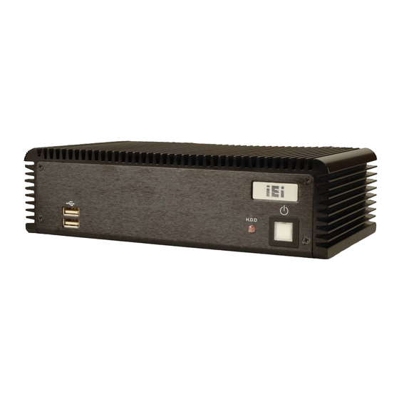
Page 31: External Overview
An overview of the front panel is shown in Figure 2-4 below. Figure 2-4: ECW-281BB6 Front Panel 2.3.2 Rear Panel The rear panel of the ECW-281BB6 provides access to the following external I/O connectors. 2 x USB port connectors 2 x RJ-45 Ethernet connector... -
Page 32: Bottom Surface
Before removing the bottom access panel, make sure the system has been turned off and all power connectors unplugged. The bottom surface of the ECW-281BB6 contains the retention screw holes for the VESA MIS-D 100 wall-mount kit, two-side mounting brackets and DIN mount bracket. -
Page 33: Internal Overview
ECW-281BB6 Embedded System Figure 2-6: Bottom Surface 2.4 Internal Overview The ECW-281BB6 internal components are listed below: 1 x IEI WAFER motherboard (preinstalled) 1 x IEI power module (preinstalled) 1 x SO-DIMM module (preinstalled) 1 x Hard drive bracket and IDE cable support one IDE hard disk All the components are accessed by removing the bottom surface. -
Page 34: Figure 2-7: Internal Overview
ECW-281BB6 Embedded System Figure 2-7: Internal Overview Page 34... -
Page 35: System Components
ECW-281BB6 Embedded System Chapter System Components Page 35... -
Page 36: Ecw-281Bb6 Embedded System Motherboard
3.1.2 WAFER-8522 Motherboard Overview The locations of the WAFER-8522 jumpers and connectors used on the ECW-281BB6 are shown in Figure 3-1 below. Figure 3-1: WAFER-8522 Jumper and Connector Locations... -
Page 37: Cpu Support
ECW-281BB6 Embedded System 3.1.3 CPU Support NOTE: The ECW-281BB6 has a preinstalled 1GHz Celeron M CPU on-board. If the CPU fails, the motherboard has to be replaced. Please contact the IEI reseller or vendor you purchased the ECW-281BB6 from or contact an IEI sales representative directly. -
Page 38: Peripheral Interface Connectors
ECW-281BB6 Embedded System 3.2 Peripheral Interface Connectors Section 3.2.1 lists all the peripheral interface connectors seen in Section 3.1.2. 3.2.1 Peripheral Interface Connectors Table 3-2 shows a list of the peripheral interface connectors on the WAFER-8522. Detailed descriptions of these connectors can be found in Section 3.3. -
Page 39: Internal Peripheral Connectors
ECW-281BB6 Embedded System Connector Type Label Ethernet connectors RJ-45 connector LAN1, LAN2 RS-232 serial port connector DB-9 connector COM1 USB ports USB port VGA port connector 15-pin female VGA1 Table 3-3: Rear Panel Connectors 3.3 Internal Peripheral Connectors Internal peripheral connectors are found on the motherboard and are only accessible when the motherboard is outside of the chassis. -
Page 40: Atx Power Connector
ECW-281BB6 Embedded System Figure 3-2: AT Power Connector Location PIN NO. DESCRIPTION +12V GROUND GROUND Table 3-4: AT Power Connector Pinouts 3.3.2 ATX Power Connector CN Label: 3-pin wafer connector (1x3) CN Type: See Figure 3-3 CN Location: See Table 3-5 CN Pinouts: The 3-pin ATX power connector is connected to an ATX power supply. -
Page 41: Audio Connector
ECW-281BB6 Embedded System Figure 3-3: ATX Power Connector Location PIN NO. DESCRIPTION +5V_SB GROUND PS_ON Table 3-5: ATX Power Connector Pinouts 3.3.3 Audio Connector CN Label: 10-pin box header (2x5) CN Type: See Figure 3-4 CN Location: See Table 3-6... -
Page 42: Ide Connector
ECW-281BB6 Embedded System Figure 3-4: Audio Connector Pinouts PIN NO. DESCRIPTION PIN NO. DESCRIPTION LINEOUT_R LINEIN_R GROUND GROUND LINEOUT_L LINEIN_L GROUND GROUND MIC1IN MIC2IN Table 3-6: Audio Connector Pinouts 3.3.4 IDE Connector CN Label: IDE1 44-pin box header (2x22) CN Type:... -
Page 43: Figure 3-5: Ide Device Connector Location
ECW-281BB6 Embedded System Figure 3-5: IDE Device Connector Location PIN NO. DESCRIPTION PIN NO. DESCRIPTION RESET# GROUND DATA 7 DATA 8 DATA 6 DATA 9 DATA 5 DATA 10 DATA 4 DATA 11 DATA 3 DATA 12 DATA 2 DATA 13... -
Page 44: Led Connector
ECW-281BB6 Embedded System DATA 0 DATA 15 GROUND DMARQ GROUND IOW# GROUND IOR# GROUND IORDY BALE DMACK# GROUND INTERRUPT PDIAG HDC CS0# HDC CS1# HDD ACTIVE# GROUND GROUND Table 3-7: IDE Connector Pinouts 3.3.5 LED Connector CN Label: 6-pin header (1x6) -
Page 45: Power Button Connector
ECW-281BB6 Embedded System Figure 3-6: LED Connector Locations PIN NO. DESCRIPTION GROUND GROUND HDLED+ HDLED- Table 3-8: LED Connector Pinouts 3.3.6 Power Button Connector CN Label: 2-pin wafer connector (1x2) CN Type: See Figure 3-7 CN Location: See Table 3-9... -
Page 46: Reset Button Connector
ECW-281BB6 Embedded System Figure 3-7: Power Button Connector Location PIN NO. DESCRIPTION Button+ Button- Table 3-9: Power Button Connector Pinouts 3.3.7 Reset Button Connector CN Label: 2-pin wafer connector (1x2) CN Type: See Figure 3-8 CN Location: See Table 3-10... -
Page 47: Serial Port Connector (Rs-232/422/485)
ECW-281BB6 Embedded System PIN NO. DESCRIPTION RESET# GROUND Table 3-10: Reset Button Connector Pinouts 3.3.8 Serial Port Connector (RS-232/422/485) CN Label: COM2 14-pin header (2x7) CN Type: See Figure 3-9 CN Location: See Table 3-11 CN Pinouts: The serial port connectors connect to RS-232, RS-422 or RS-485 serial port device. -
Page 48: Serial Port Connector (Com 3, Com 4, Com 5 And Com 6)
ECW-281BB6 Embedded System Table 3-11: RS-232/422/485 Serial Port Connector Pinouts 3.3.9 Serial Port Connector (COM 3, COM 4, COM 5 and COM 6) CN Label: 40-pin header (2x20) CN Type: See Figure 3-10 CN Location: See Table 3-12 CN Pinouts: The 40-pin serial port connector contains the following four serial ports, COM 3, COM 4, COM 5 and COM 6. -
Page 49: Internal Usb Connectors
ECW-281BB6 Embedded System PIN NO. DESCRIPTION PIN NO. DESCRIPTION DCD_COM3 DSR_COM3 RXD_COM3 RTS_COM3 TXD_COM3 CTS_COM3 DTR_COM3 RI_COM3 DCD_COM4 DSR_COM4 RXD_COM4 RTS_COM4 TXD_COM4 CTS_COM4 DTR_COM4 RI_COM4 DCD_COM5 DSR_COM5 RXD_COM5 RTS_COM5 TXD_COM5 CTS_COM5 DTR_COM5 RI_COM5 DCD_COM6 DSR_COM6 RXD_COM6 RTS_COM6 TXD_COM6 CTS_COM6 DTR_COM6... -
Page 50: External Peripheral Interface Connectors
ECW-281BB6 Embedded System One 2x4 pin connector provides connectivity to two USB 2.0 ports. The USB ports are used for I/O bus expansion. Figure 3-11: Internal USB Connector Location PIN NO. DESCRIPTION PIN NO. DESCRIPTION GROUND DATA0- DATA0+ DATA0+ DATA0-... -
Page 51: Ethernet Connector
ECW-281BB6 Embedded System Figure 3-12: WAFER-8522 On-board External Interface Connectors 3.4.2 RJ-45 Ethernet Connector LAN1 and LAN2 CN Label: RJ-45 CN Type: See Figure 3-12 CN Location: See Table 3-14 CN Pinouts: The RJ-45 Ethernet connector on the WAFER-8522 provides connectivity to a GbE Ethernet connection between the WAFER-8522 and a Local Area Network (LAN) through a network hub. -
Page 52: Serial Port Connector (Com1)
ECW-281BB6 Embedded System The RJ-45 Ethernet connector has two status LEDs, one green and one yellow. The green LED indicates activity on the port and the yellow LED indicates the port is linked. See Table 3-15. SPEED LED ACT/LINK LED... -
Page 53: Usb Combo Ports
ECW-281BB6 Embedded System Figure 3-14: Serial Port Pinout Locations 3.4.4 USB Combo Ports CN Label: USB Combo port CN Type: See Figure 3-12 CN Location: See Table 3-17 CN Pinouts: The two USB combo ports provide connectivity to USB devices. The USB port support both USB 1.1 and USB 2.0. -
Page 54: Figure 3-15: Vga Connector
ECW-281BB6 Embedded System The standard 15-pin female DB15 VGA connector connects to a CRT or LCD monitor directly. DESCRIPTION DESCRIPTION GREEN GROUND BLUE DDCDAT GROUND HSYNC VSYNC GROUND DDCCLK GROUND Table 3-18: VGA Connector Pinouts Figure 3-15: VGA Connector Page 54... -
Page 55: Wafer-8522 Motherboard On-Board Jumpers
ECW-281BB6 Embedded System 3.5 WAFER-8522 Motherboard On-board Jumpers NOTE: A jumper is a metal bridge used to close an electrical circuit. It consists of two or three metal pins and a small metal clip (often protected by a plastic cover) that slides over the pins to connect them. -
Page 56: Table 3-21: Jp2 Clear Cmos Jumper Settings
ECW-281BB6 Embedded System If the WAFER-8522 fails to boot due to improper BIOS settings, the CMOS can be cleared using the battery connector. Disconnect the battery from the connector for a few seconds then reconnect the battery. The CMOS should be cleared. -
Page 57: Com Port Setting Jumper
ECW-281BB6 Embedded System Figure 3-17: JP2 Clear CMOS Jumper 3.5.2 COM Port Setting Jumper Jumper Label: 3-pin header Jumper Type: See Table 3-21 Jumper Settings: See Figure 3-18 Jumper Location: The JP4 jumper sets the communication protocol used by the second serial communications port (COM 2) as RS-232, RS-422 or RS-485. -
Page 58: Lcd Voltage Selection
ECW-281BB6 Embedded System Figure 3-18: COM Port Setting Jumper Location 3.5.3 LCD Voltage Selection WARNING: Permanent damage to the screen and WAFER-8522 may occur if the wrong voltage is selected with this jumper. Please refer to the user guide that came with the monitor to select the correct voltage. -
Page 59: Lcd Resolution Selection
ECW-281BB6 Embedded System The LCD Voltage Selection jumper location is shown in Figure 3-19. Figure 3-19: LCD Voltage Selection Jumper Location 3.5.4 LCD Resolution Selection Jumper Label: 8-pin header Jumper Type: See Table 3-23 Jumper Settings: See Figure 3-20 Jumper Location: Use the LCD Resolution jumper to select the resolution of the LCD. -
Page 60: Connector Mappings
ECW-281BB6 Embedded System Short Open Open Open Type 7: 1280x768 18-bit Short Open Open Short Type 8: 1600x1050 48-bit Short Open Short Open Type 9: 1920x1200 36-bit Short Open Short Short Type 10: 1024x768 24-bit Short Short Open Open Type 11: Reserved... -
Page 61: Power Connector
ECW-281BB6 Embedded System 3.6.1 Power Connector The connector mapping for the power module output power connector and the motherboard input power connector are shown in Table 3-24. WAFER-8522 Power Module CN5: Power CN4: Output Power Pin 1 Pin 4 Pin 2... - Page 62 ECW-281BB6 Embedded System THIS PAGE IS INTENTIONALLY LEFT BLANK Page 62...
-
Page 63: Installation
ECW-281BB6 Embedded System Chapter Installation Page 63... -
Page 64: Anti-Static Precautions
Electrostatic discharge (ESD) can cause serious damage to electronic components, including the WAFER series motherboard and the power module. (Dry climates are especially susceptible to ESD.) It is therefore critical that whenever the ECW-281BB6 is opened and any electrical component handled, the following anti-static precautions are strictly adhered to. -
Page 65: Unpacking
Step 6: 4.2.2 Unpacking After the ECW-281BB6 is received make sure the following components are included in the package. If any of these components are missing, please contact the ECW-281BB6 reseller or vendor where it was purchased or contact an IEI sales representative immediately. -
Page 66: Table 4-1: Package List Contents
ECW-281BB6 Embedded System Mini jumper pack Quick installation guide Driver and manual CD Power Adaptor (for WD models only) Wall mount kit (optional) Table 4-1: Package List Contents Page 66... -
Page 67: Bottom Surface Removal
Step 1: the chassis with six retention screws (Figure 4-1). All six screws must be removed. Figure 4-1: Bottom Surface Retention Screws Gently remove the bottom surface from the ECW-281BB6. Step 2: Step 0: 4.2.4 Configure the Jumper Settings To configure the jumper settings, please follow the steps below. -
Page 68: Ide Hard Drive Installation
ECW-281BB6 Embedded System 4.2.5 IDE Hard Drive Installation One 2.5” IDE hard drive supported. The IDE drive is installed into a hard drive bracket attached on the inside of the bottom panel (Figure 4-2). Figure 4-2: Hard Drive Bracket To install the hard drive into the system, please follow the steps below. -
Page 69: Figure 4-4: Hdd Retention Screws
ECW-281BB6 Embedded System Place the HDD into the bracket. Step 3: Align the retention screw holes in the HDD with those in the bottom of the Step 4: bracket. Secure the HDD with the bracket by inserting four retention screws into the Step 5: bottom of the bracket (Figure 4-4). -
Page 70: Mounting The System With Mounting Brackets
HDD bracket with those in the back of the bottom surface. Reinsert the four previously removed retention screws. Step 9: Connect the IDE cable connector in the ECW-281BB6 to the HDD. Step 10: Replace the bottom surface to the bottom panel by reinserting the six previously Step 11: removed retention screws. -
Page 71: Mounting The System With Wall Mount Kit
ECW-281BB6 Embedded System Figure 4-6: Mounting Bracket Retention Screws Drill holes in the intended installation surface. Step 4: Align the mounting holes in the sides of the mounting brackets with the predrilled Step 5: holes in the mounting surface. Insert four retention screws, two in each bracket, to secure the system to the Step 6: wall. -
Page 72: Figure 4-7: Wall-Mounting Bracket
(Figure 4-8). Align the mounting screws on the ECW-281BB6 bottom panel with the mounting Step 1: holes on the bracket. -
Page 73: Din Mounting
ECW-281BB6 Embedded System Figure 4-8: Mount the Embedded System 4.2.8 DIN Mounting To mount the ECW-281BB6 embedded system onto a DIN rail, please follow the steps below. Attach the DIN rail mounting bracket to the bottom panel of the embedded Step 3: system. -
Page 74: Figure 4-9: Din Rail Mounting Bracket
ECW-281BB6 Embedded System Figure 4-9: DIN Rail Mounting Bracket Make sure the inserted screw in the center of the bracket is at the lowest Step 4: position of the elongated hole (Figure 4-10). Figure 4-10: Screw Locations Place the DIN rail flush against the back of the mounting bracket making sure Step 5: the edges of the rail are between the upper and lower clamps (Figure 4-11). -
Page 75: Cable Connections
ECW-281BB6 Embedded System Figure 4-11: Mounting the DIN RAIL Secure the DIN rail to the mounting bracket by turning the top screw clockwise. Step 6: This draws the lower clamp up and secures the embedded system to the DIN rail (Figure 4-12).Step 0:... -
Page 76: Power -O N Procedure
ECW-281BB6 Embedded System USB devices can be connected to the system. The cable connection locations are shown in Figure 2-5. 4.3 Power-On Procedure 4.3.1 Installation Checklist WARNING: Make sure a power supply with the correct input voltage is being fed into the system. -
Page 77: Power-On Procedure
The chassis ground is connected to the ECW chassis internally. The cable ground is connected to the ground pin on the input power connector of the power module. 4.3.3 Power-on Procedure To power-on the ECW-281BB6 please follow the steps below: Push the power button. Step 1: Once turned on, the power button should turns to blue. - Page 78 ECW-281BB6 Embedded System THIS PAGE IS INTENTIONALLY LEFT BLANK Page 78...
-
Page 79: Bios Settings
ECW-281BB6 Embedded System Chapter BIOS Settings Page 79... -
Page 80: Introduction
ECW-281BB6 Embedded System 5.1 Introduction A licensed copy of AMI BIOS is preprogrammed into the ROM BIOS. The BIOS setup program allows users to modify the basic system configuration. This chapter describes how to access the BIOS setup program and the configuration options that may be changed. -
Page 81: Getting Help
ECW-281BB6 Embedded System F1 key General help, only for Status Page Setup Menu and Option Page Setup Menu F2 /F3 key Change color from total 16 colors. F2 to select color forward. F10 key Save all the CMOS changes, only for Main Menu Table 5-1: BIOS Navigation Keys 5.1.3 Getting Help... -
Page 82: Main
ECW-281BB6 Embedded System 5.2 Main The Main BIOS menu (BIOS Menu 1) appears when the BIOS Setup program is entered. The Main menu gives an overview of the basic system information. BIOS Menu 1: Main System Overview The System Overview lists a brief summary of different system components. The fields in System Overview cannot be changed. -
Page 83: Advanced
ECW-281BB6 Embedded System Count: The number of CPUs on the motherboard System Memory: Displays the auto-detected system memory. Lists memory size Size: The System Overview field also has two user configurable fields: System Time [xx:xx:xx] Use the System Time option to set the system time. Manually enter the hours, minutes and seconds. -
Page 84: Cpu Configuration
ECW-281BB6 Embedded System BIOS Menu 2: Advanced 5.3.1 CPU Configuration Use the CPU Configuration menu (BIOS Menu 3) to view detailed CPU specifications and configure the CPU. Page 84... -
Page 85: Menu 3: Cpu Configuration
ECW-281BB6 Embedded System BIOS Menu 3: CPU Configuration The CPU Configuration menu (BIOS Menu 3) lists the following CPU details: Manufacturer: Lists the name of the CPU manufacturer Brand String: Lists the brand name of the CPU being used Frequency: Lists the CPU processing speed... -
Page 86: Ide Configuration
ECW-281BB6 Embedded System Execute Bit Disable [Enabled] Use the Execute Bit Disable BIOS function to protect the system from buffer overflow attacks. Code can be executed in any memory area. Disabled Code execution in data-only memory pages is Enabled EFAULT prohibited. - Page 87 ECW-281BB6 Embedded System Use the OnBoard PCI IDE Controller BIOS option to specify the IDE channels used by the onboard PCI IDE controller. The following configuration options are available. Prevents the system from using the onboard IDE Disabled controller Only allows the system to detect the Primary IDE...
- Page 88 ECW-281BB6 Embedded System Prevents hard disks from being overwritten Enabled IDE Detect Time Out (Sec) [35] The IDE Detect Time Out (Sec) BIOS option specifies the maximum time (in seconds) the AMI BIOS will search for IDE devices. This allows fine-tunes the settings to allow for faster boot times.
-
Page 89: Ide Master, Ide Slave
ECW-281BB6 Embedded System cable used. The motherboard onboard IDE controller detects Host the type of IDE cable used. The IDE disk drive to detects the type of IDE cable Device used. IDE Master and IDE Slave When entering setup, BIOS auto detects the presence of IDE devices. BIOS displays the status of the auto detected IDE devices. -
Page 90: Menu 5: Ide Master And Ide Slave Configuration
ECW-281BB6 Embedded System BIOS Menu 5: IDE Master and IDE Slave Configuration Auto-Detected Drive Parameters The “grayed-out” items in the left frame are IDE disk drive parameters automatically detected from the firmware of the selected IDE disk drive. The drive parameters are listed as follows: Type: Lists the device type (e.g. - Page 91 ECW-281BB6 Embedded System S.M.A.R.T.: Indicates whether or not the Self-Monitoring Analysis and Reporting Technology protocol is supported. Type [Auto] Use the Type BIOS option select the type of device the AMIBIOS attempts to boot from after the Power-On Self-Test (POST) is complete.
- Page 92 ECW-281BB6 Embedded System the specified channel. BIOS auto detects the LBA mode control on the specified Auto EFAULT channel. Block (Multi Sector Transfer) [Auto] Use the Block (Multi Sector Transfer) to disable or enable BIOS to auto detect if the device supports multi-sector transfers.
-
Page 93: Super Io Configuration
ECW-281BB6 Embedded System PIO mode 4 selected with a maximum transfer rate of 16.6MBps (This setting generally works with all hard disk drives manufactured after 1999. For other disk drives, such as IDE CD-ROM drives, check the specifications of the drive.) DMA Mode [Auto] Use the DMA Mode BIOS selection to adjust the DMA mode options. -
Page 94: Menu 6: Super Io Configuration
ECW-281BB6 Embedded System Use the Super IO Configuration menu (BIOS Menu 6) to set or change the configurations for the FDD controllers, parallel ports and serial ports. BIOS Menu 6: Super IO Configuration Serial Port1 Address [3F8/IRQ4] Use the Serial Port1 Address option to select the Serial Port 1 base address. - Page 95 ECW-281BB6 Embedded System Serial Port1 Mode [Normal] Use the Serial Port1 Mode option to select the transmitting and receiving mode for the first serial port. (Default) Serial Port 1 mode is normal Normal Serial Port 1 mode is IrDA IrDA...
- Page 96 ECW-281BB6 Embedded System The Restore on AC Power Loss BIOS option specifies what state the system returns to if there is a sudden loss of power to the system. The system remains turned off Power Off The system turns on...
- Page 97 ECW-281BB6 Embedded System Serial Port4 Address [2E8] Use the Serial Port4 IRQ option to select the interrupt address for serial port 4. No base address is assigned to serial port 3 Disabled Serial port 4 I/O port address is 3F8...
- Page 98 ECW-281BB6 Embedded System Serial port 5 I/O port address is 2E0 Serial port 5 I/O port address is 2D8 Serial port 5 I/O port address is 2D0 Serial Port5 IRQ [11] Use the Serial Port5 IRQ option to select the interrupt address for serial port 5.
-
Page 99: Hardware Health Configuration
ECW-281BB6 Embedded System Serial port 6 IRQ address is 3 Serial port 6 IRQ address is 9 Serial port 6 IRQ address is 10 EFAULT Serial port 6 IRQ address is 11 5.3.4 Hardware Health Configuration The Hardware Health Configuration menu (BIOS Menu 7) shows the operating temperature, fan speeds and system voltages. -
Page 100: Mps Configuration
ECW-281BB6 Embedded System System Temperatures: The following system temperatures are monitored Temperature Sensor #1 Temperature Sensor #2 Voltages: The following system voltages are monitored CPU Core +3.3V +5.0V +1.5V VBAT 5.3.5 MPS Configuration Use the MPS Configuration menu (BIOS Menu 8) to select `he multi-processor table. -
Page 101: Trusted Computing
ECW-281BB6 Embedded System Use the Multiprocessor Specification (MPS) for OS option to specify the MPS version to be used. MPS version 1.1 is used EFAULT MPS version 1.4 is used 5.3.6 Trusted Computing Use the Trusted Computing menu (BIOS Menu 9) to configure TPM parameters. -
Page 102: Usb Configuration
ECW-281BB6 Embedded System TPM function not supported Disabled EFAULT TPM function supported Enabled 5.3.7 USB Configuration Use the USB Configuration menu (BIOS Menu 10) to read USB configuration information and configure the USB settings. BIOS Menu 10: USB Configuration USB Configuration The USB Configuration field shows the system USB configuration. - Page 103 ECW-281BB6 Embedded System The USB Devices Enabled field lists the USB devices that are enabled on the system USB Function [4 USB Ports] Use the USB Function BIOS option to enable USB host controllers. USB function support disabled Disabled The USB controller activates 2 USB ports...
-
Page 104: Usb Mass Storage Device Configuration
ECW-281BB6 Embedded System Use the USB2.0 Controller Mode option to set the speed of the USB2.0 controller. The controller is capable of operating at 12Mb/s FullSpeed EFAULT The controller is capable of operating at 480Mb/s HiSpeed 5.3.7.1 USB Mass Storage Device Configuration Use the USB Mass Storage Device Configuration menu (BIOS Menu 11) to configure USB mass storage class devices. - Page 105 ECW-281BB6 Embedded System Use the Emulation Type BIOS option to specify the type of emulation BIOS has to provide for the USB device. NOTE: Please note that the device’s formatted type and the emulation type provided by the BIOS must match for a device to boot properly. If both types do not match then device’s behavior is undefined.
-
Page 106: Boot
ECW-281BB6 Embedded System option. 5.4 Boot Use the Boot menu (BIOS Menu 12) to configure system boot options. BIOS Menu 12: Boot 5.4.1 Boot Settings Configuration Use the Boot Settings Configuration menu (BIOS Menu 13) to configure advanced system boot options. -
Page 107: Bios Menu 13: Boot Settings Configuration
ECW-281BB6 Embedded System BIOS Menu 13: Boot Settings Configuration Quick Boot [Enabled] Use the Quick Boot BIOS option to make the computer speed up the boot process. No POST procedures are skipped Disabled Some POST procedures are skipped to decrease... -
Page 108: Boot Device Priority
ECW-281BB6 Embedded System Boot Display Device [Auto] The Boot Display Device BIOS option selects the display device the system uses when it boots. The available options are listed below: Auto EFAULT CRT + LFP Spread Spectrum Mode [Disabled] Use the Spread Spectrum Mode option to reduce the EMI. Excess EMI is generated when the system clock generator pulses have extreme values. -
Page 109: Removable Drives
ECW-281BB6 Embedded System BIOS Menu 14: Boot Device Priority Settings 5.4.3 Removable Drives Use the Removable Drives menu (BIOS Menu 15) to specify the boot sequence of the available drives. When the menu is opened, the removable drives connected to the... -
Page 110: Security
ECW-281BB6 Embedded System The boot sequence from the available devices is selected. If the “1st Drive” option is selected a list of available drives is shown. Select the first drive the system boots from. If the “1st Drive” is not used for booting this option may be disabled. -
Page 111: Menu 16: Security
ECW-281BB6 Embedded System BIOS Menu 16: Security Change Supervisor Password Use the Change Supervisor Password to set or change a supervisor password. The default for this option is Not Installed. If a supervisor password must be installed, select this field and enter the password. After the password has been added, Install appears next to Change Supervisor Password. -
Page 112: Chipset
ECW-281BB6 Embedded System Use the Clear User Password to clear a user password. 5.6 Chipset Use the Chipset menu (BIOS Menu 17) to access the NorthBridge and SouthBridge configuration menus WARNING! Setting the wrong values for the Chipset BIOS selections in the Chipset BIOS menu may cause the system to malfunction. -
Page 113: Menu 18:Northbridge Chipset Configuration
ECW-281BB6 Embedded System Use the NorthBridge Configuration menu (BIOS Menu 18) to configure the northbridge chipset. BIOS Menu 18:NorthBridge Chipset Configuration DRAM Frequency [Auto] Use the DRAM Frequency option to specify the DRAM frequency or allow the system to automatically detect the DRAM frequency. - Page 114 ECW-281BB6 Embedded System Use the Configure DRAM Timing by SPD option to determine if the system uses the SPD (Serial Presence Detect) EEPROM to configure the DRAM timing. The SPD EEPROM contains all necessary DIMM specifications including the speed of the individual components such as CAS and bank cycle time as well as valid settings for the module and the manufacturer's code.
- Page 115 ECW-281BB6 Embedded System The Init. Graphic Adapter Priority option selects the graphics controller the system uses as a primary boot device. The options are: Internal VGA PCI/Int-VGA EFAULT Internal Graphics Mode Select [Enable, 8MB] Use the Internal Graphic Mode Select option to specify the amount of system memory that can be used by the Internal graphics device.
- Page 116 ECW-281BB6 Embedded System Auto EFAULT CRT+LFP Flat Panel Type [1280x1024] The Flat Panel Type BIOS option specifies the flat panel PC type being used. NOTE: Please refer to the technical documents that came with the flat panel PC to ensure the correct settings are selected.
-
Page 117: Southbridge Configuration
ECW-281BB6 Embedded System panel. The connected local flat panel is forced to scale. Forced Scaling Disable the local flat panel scaling. Disabled 5.6.2 SouthBridge Configuration The SouthBridge Intel ICH4 Configuration menu (BIOS Menu 19) the southbridge chipset to be configured. -
Page 118: Power Key
ECW-281BB6 Embedded System The onboard AC’97 is disabled Disabled OnBoard Lan Rom [Disabled] The OnBoard Lan Rom option enables or disables the onboard LAN. The onboard LAN device automatically detected and Enabled enabled Onboard LAN device manually disabled Disabled EFAULT 5.7 Power Key... -
Page 119: Menu 20:Power
ECW-281BB6 Embedded System BIOS Menu 20:Power Power Type Select [AT] Use the Power Type Select BIOS option to select the power supply that is connected to the system. An AT power supply is connected to the system EFAULT An ATX power supply is connected to the system... -
Page 120: Exit
ECW-281BB6 Embedded System When the power button is pressed the system is either On/Off EFAULT turned on or off When the power button is pressed the system goes into Suspend suspend mode 5.8 Exit The Exit menu (BIOS Menu 21) loads default BIOS values, optimal failsafe values and to save configuration changes. - Page 121 ECW-281BB6 Embedded System Discard Changes and Exit If configuration changes are complete but do need to be saved, select this option to exit the BIOS menus. Discard Changes If configuration changes are complete but do need to be saved but BIOS still needs to be run , select this option.
- Page 122 ECW-281BB6 Embedded System THIS PAGE IS INTENTIONALLY LEFT BLANK Page 122...
-
Page 123: Driver Installation
ECW-281BB6 Embedded System Chapter Driver Installation Page 123... -
Page 124: Available Software Drivers
The ECW-281BB6 embedded system has five software drivers: Chipset Audio All five drivers can be found on the CD that came with the ECW-281BB6. To install the drivers please follow the instructions in the sections below 6.2 Chipset Driver Installation To install the chipset driver, please follow the steps below: Insert the CD into the system. -
Page 125: Figure 6-2: Welcome Screen
ECW-281BB6 Embedded System The “Welcome” window in Figure 6-2 appears next. Step 4: Figure 6-2: Welcome Screen Click “Next” and the license agreement shown in Figure 6-3 appears. Step 5: Figure 6-3: License Agreement Agree to the license terms by clicking “Yes”. The “Readme” in Figure 6-4 Step 6: appears. -
Page 126: Figure 6-4: Readme Information
ECW-281BB6 Embedded System Figure 6-4: Readme Information Click “Yes”. The driver is installed on the computer. After the installation is Step 7: complete, the installation complete screen shown in Figure 6-5 appears. Select the preferred option and click “Finish” to complete the installation process. -
Page 127: Realtek Audio Driver Installation
ECW-281BB6 Embedded System 6.3 RealTek Audio Driver Installation To install the RealTek AC’97 Audio driver, please follow the steps below: Insert the CD into the system. Open the CD folder and locate the AUDIO Step 1: DRIVER A3.79 directory. Open the directory and look for icon for the setup.exe installation file. -
Page 128: Figure 6-8: Audio Driver Welcome Screen
ECW-281BB6 Embedded System shield starts to configure the new software as shown in Figure 6-9. Figure 6-8: Audio Driver Welcome Screen Figure 6-9: Audio Driver Software Configuration At this stage the “Digital Signal Not Found” screen shown in Figure 6-10 Step 5: appears. -
Page 129: Figure 6-10: Audio Driver Digital Signal
ECW-281BB6 Embedded System Figure 6-10: Audio Driver Digital Signal At this stage the clicking the “Yes” button in Figure 6-10 appears, the installation Step 6: of the driver begins. See Figure 6-11. Figure 6-11: Audio Driver Installation Begins After the driver installation process is complete, a confirmation screen shown in... -
Page 130: Intel Graphics Media Accelerator Driver
ECW-281BB6 Embedded System Figure 6-12: Audio Driver Installation Complete The confirmation screen shown in Figure 6-12 allows user to restart the Step 8: computer immediately after the installation is complete or to restart the computer later. For the settings to take effect the computer must be restarted. Once decided when to restart the computer, click the “Finish”... -
Page 131: Figure 6-13: Gma Driver Installation Welcome Screen
ECW-281BB6 Embedded System Figure 6-13: GMA Driver Installation Welcome Screen To continue installing click “Next” and a license agreement shown in Figure Step 3: 6-14 appears. Read through the license agreement. Figure 6-14: GMA Driver License Agreement Accept the terms and conditions stipulated in the license agreement by clicking Step 4: the “Yes”... -
Page 132: Lan Driver Installation
ECW-281BB6 Embedded System Figure 6-15: GMA Driver Installing Notice After the driver installation process is complete, a confirmation screen shown in Step 5: Figure 6-16 appears. Figure 6-16: GMA Driver Installation Complete The confirmation screen shown in Figure 6-16 allows user to restart the... -
Page 133: Figure 6-17: Lan License Agreement
ECW-281BB6 Embedded System Figure 6-17: LAN License Agreement Accept the License Agreement by clicking “Next.” The follow-up window Step 3: prompts for the directory the driver is stored in. (See Figure 6-18) Figure 6-18: Select the Driver Directory After selecting the directory the driver is installed in, click “Next.” The screen in Step 4: Figure 6-19 appears. -
Page 134: Figure 6-19: Lan Driver Configuration
ECW-281BB6 Embedded System Figure 6-19: LAN Driver Configuration In Figure 6-19, there are three options. Step 5: Install Base Driver Installs the base driver Make Driver Disk Copies the driver to disk View Release Notes Opens word document of the release notes... -
Page 135: Troubleshooting And Maintenance
ECW-281BB6 Embedded System Chapter Troubleshooting and Maintenance Page 135... -
Page 136: Ecw-281Bb6 System Maintenance Overview
Failure to follow these instructions may lead to personal injury and system damage. To preserve the working integrity of the ECW-281BB6 embedded system, the system must be properly maintained. If embedded system components need replacement, the proper maintenance procedures must be followed to ensure the system can continue to operate normally. -
Page 137: The System Doesn't Boot Up
ECW-281BB6 Embedded System Make sure the power button is turned on. Step 8: Plug the system into a monitor and check to see if anything appears on the Step 9: screen. If the boot-up screen appears it means the power LED has become disconnected. -
Page 138: More Troubleshooting
If all troubleshooting measures have been taken and the system still fails to start, contact the IEI reseller or vendor you purchased the ECW-281BB6 from or contact an IEI sales representative directly. To contact an IEI sales representative, please send an email to sales@iei.com.tw. -
Page 139: So-Dimm Replacement
To replace a SO-DIMM memory module into a SO-DIMM socket, please follow the steps below. Locate the SO-DIMM socket. Place the ECW-281BB6 on an anti-static pad Step 1: with the bottom panel facing up and the bottom surface removed. (see Section 4.2.3). -
Page 140: Figure 7-2: So-Dimm Removal
ECW-281BB6 Embedded System Figure 7-2: SO-DIMM Removal Take the SO-DIMM out from the thermal bracket. Remove the thermal pad on Step 4: the thermal bracket and remove the two retention screws (Figure 7-3). Open the thermal bracket and take the SO-DIMM out. -
Page 141: Figure 7-4: So-Dimm Installation
ECW-281BB6 Embedded System plastic bridge in the socket. Insert the SO-DIMM. Push the SO-DIMM chip into the socket at an angle. Step 8: (See Figure 7-4) Figure 7-4: SO-DIMM Installation Open the SO-DIMM socket arms. Gently pull the arms of the SO-DIMM socket Step 9: out and push the rear of the SO-DIMM down. - Page 142 ECW-281BB6 Embedded System THIS PAGE IS INTENTIONALLY LEFT BLANK Page 142...
-
Page 143: Iei Embedded System Series
ECW-281BB6 Embedded System Appendix IEI Embedded System Series Page 143... -
Page 144: Iei Embedded
ECW-281BB6 Embedded System A.1 IEI Embedded System Series A.1.1 Overview IEI embedded industrial PC systems are ideal for manufacturing and automation environments where heavy processing demands exist. These systems are designed to operate effectively within high-stress environments that have diverse operational conditions. -
Page 145: Iei Embedded System Series Variations
ECW-281BB6 Embedded System A.1.3 IEI Embedded System Series Variations The differences between the series are listed below. Motherboard Cooling CompactFlash Drive Bays ECW-180A WAFER Two cooling fans One CF slot None ECW-180B WAFER Fanless One CF slot None ECW-181A WAFER... -
Page 146: Amd ® Geode
ECW-281BB6 Embedded System Model Number System Chipset DC Input Drive Bays ® ECW-181AS1WD CS5536 9V ~ 36V Two 2.5” HDD ® ECW-181BS1 CS5536 None Two 2.5” HDD ® ECW-181BS1WD CS5536 9V ~ 36V None Two 2.5” HDD ECK-3688GA ® CS5536 One 2.5”... -
Page 147: Via Mark ® 800Mhz Solutions
ECW-281BB6 Embedded System Model Number System Chipset DC Input Drive Bays ® ECW-181BS3 VT8237R+ None Two 2.5” HDD ® ECW-181BS3WD VT8237R+ 9V ~ 36V None Two 2.5” HDD ® ECK-3688GB VT8237R+ One 2.5” HDD ® ® Table A-4: VIA LUKE Embedded System Solutions ®... -
Page 148: Intel Pentium M 1.6Ghz Solutions
ECW-281BB6 Embedded System Model Number System Chipset DC Input Drive Bays ECW-180AS5XWD SiS 661CX + SiS 964 9V ~ 36V None ECW-181AS5X SiS 661CX + SiS 964 Two 2.5” HDD ECW-181AS5XWD SiS 661CX + SiS 964 9V ~ 36V Two 2.5” HDD ECN-171BSE0-CM15G Intel®... -
Page 149: Intel Socket 479 Pentium /Celeron M 2Ghz Solutions
ECW-281BB6 Embedded System ® ® ® A.2.8 Intel Socket 479 Pentium /Celeron M 2GHz Solutions ® ® ® All the models listed in the table below support an Intel Socket 479 Pentium /Celeron 2GHz CPU with a 400/533MHz FSB (front side bus). - Page 150 ECW-281BB6 Embedded System THIS PAGE IS INTENTIONALLY LEFT BLANK Page 150...
-
Page 151: Bbios Menu Options
ECW-281BB6 Embedded System Chapter BIOS Menu Options Page 151... -
Page 152: Bios Configuration Options
ECW-281BB6 Embedded System B.1 BIOS Configuration Options Below is a list of BIOS configuration options described in Chapter 5. System Overview ....................82 System Time [xx:xx:xx]..................83 System Date [xx/xx/xx]..................83 Execute Bit Disable [Enabled] ................86 OnBoard PCI IDE Controller [Both]..............86 ... - Page 153 ECW-281BB6 Embedded System Serial Port4 IRQ [10] ....................97 Serial Port5 Address [2F0]..................97 Serial Port5 IRQ [11] ....................98 Serial Port6 Address [2E0]..................98 Serial Port6 IRQ [10] ....................98 MPS Revision [1.1]....................100 TPM Device [Disabled] ..................101 ...
- Page 154 ECW-281BB6 Embedded System OnBoard AC97 Audio [Auto] ................117 OnBoard Lan Rom [Disabled]................118 Power Type Select [AT]..................119 Resume on Ring [Disabled] ................119 Resume on PME# [Enabled] ................119 Power Button Mode [On/Off] ................119 ...
-
Page 155: Cwatchdog Timer
ECW-281BB6 Embedded System Appendix Watchdog Timer Page 155... - Page 156 ECW-281BB6 Embedded System NOTE: The following discussion applies to DOS environment. IEI support is contacted or the IEI website visited for specific drivers for more sophisticated operating systems, e.g., Windows and Linux. The Watchdog Timer is provided to ensure that standalone systems can always recover from catastrophic conditions that cause the CPU to crash.
-
Page 157: Example Program
ECW-281BB6 Embedded System NOTE: When exiting a program it is necessary to disable the Watchdog Timer, otherwise the system resets. Example program: ; INITIAL TIMER PERIOD COUNTER W_LOOP: AX, 6F02H ;setting the time-out value BL, 30 ;time-out value is 48 seconds ;... - Page 158 ECW-281BB6 Embedded System THIS PAGE IS INTENTIONALLY LEFT BLANK Page 158...
-
Page 159: Daddress Mapping
ECW-281BB6 Embedded System Appendix Address Mapping Page 159... -
Page 160: Io Address Map
ECW-281BB6 Embedded System D.1 IO Address Map I/O address Description Range 000-01F DMA Controller 020-021 Interrupt Controller 040-043 System time 060-06F Keyboard Controller 070-07F System CMOS/Real time Clock 080-09F DMA Controller 0A0-0A1 Interrupt Controller 0C0-0DF DMA Controller 0F0-0FF Numeric data processor... -
Page 161: St Mb Memory Address Map
ECW-281BB6 Embedded System D.2 1st MB Memory Address Map Memory address Description 00000-9FFFF System memory A0000-BFFFF VGA buffer F0000-FFFFF System BIOS 1000000- Extend BIOS Table D-2: 1 MB Memory Address Map D.3 IRQ Mapping Table IRQ0 System Timer IRQ8 RTC clock... - Page 162 ECW-281BB6 Embedded System THIS PAGE IS INTENTIONALLY LEFT BLANK Page 162...
-
Page 163: Index
ECW-281BB6 Embedded System Index Page 163... - Page 164 ECW-281BB6 Embedded System 1 C 12V DC input ..........23 Celeron ............38 chipset driver........... 126 5 clear CMOS jumper ......57, 58 55W power adapter ........25 location ..........58 settings ..........58 8 CMOS ............57 clear CMOS jumper .......57 852GM .............126 COM 3............49 connector location and pinouts....49...
- Page 165 ECW-281BB6 Embedded System AT power ..........40 G ATX power ..........41 Graphics Media Accelerator....132 audio............42 COM 3 serial port ........49 H COM 4 serial port ........49 COM 5 serial port ........49 HDD ............45 COM 6 serial port ........49 activity............45 IDE............43 indicator LED .........45...
- Page 166 ECW-281BB6 Embedded System location ..........62 RJ-45 Ethernet connector....52, 53 LCD voltage selection jumper....60 pinouts ...........52 location ..........61 RJ-45 Ethernet connectors ......31 settings ..........60 RS-232.......... 49, 54, 59 COM 1 location and pinouts ....54 HDD indicator ........45 connector location and pinouts....54 power status ..........45...
- Page 167 ECW-281BB6 Embedded System USB combo port ........52 DB15 connector........55 USB port connectors........31 W V WAFER motherboard.........33 VGA ........... 55, 116, 117 wall mounting ..........74 connector..........52 wall-mounting bracket........73 connector pinouts ........55 Page 167...
Need help?
Do you have a question about the ECW-281BB6 and is the answer not in the manual?
Questions and answers