Table of Contents
Advertisement
Quick Links
Advertisement
Table of Contents

Related Manuals for IEI Technology IOPS-Q67/H61


Summary of Contents for IEI Technology IOPS-Q67/H61
-
Page 1: User Manual
IOPS-Q67/H61 Pluggable Module PC IOPS-Q67/H61 Embedded System MODEL: IOPS-Q67/H61 OPS Compliant Pluggable Module PC with Intel® Core™ i5/Celeron® G530, Intel® Q67/H61 Express Chipset, GbE LAN, DisplayPort, RS-232, USB 2.0, SDHC Slot, RoHS Compliant User Manual Page I Rev. 1.01 – November 27, 2014... - Page 2 IOPS-Q67/H61 Pluggable Module PC Revision Date Version Changes November 27, 2014 1.01 Updated document format December 4, 2012 1.00 Initial release Page II...
- Page 3 IOPS-Q67/H61 Pluggable Module PC Copyright COPYRIGHT NOTICE The information in this document is subject to change without prior notice in order to improve reliability, design and function and does not represent a commitment on the part of the manufacturer. In no event will the manufacturer be liable for direct, indirect, special, incidental, or consequential damages arising out of the use or inability to use the product or documentation, even if advised of the possibility of such damages.
- Page 4 IOPS-Q67/H61 Pluggable Module PC WARNING This device complies with Part 15 of the FCC Rules. Operation is subject to the following two conditions: (1) this device may not cause harmful interference, and(2) this device must accept any interference received, including interference that may cause undesired operation.
-
Page 5: Table Of Contents
IOPS-Q67/H61 Pluggable Module PC Table of Contents 1 INTRODUCTION......................1 1.1 O ........................2 VERVIEW 1.2 F ........................2 EATURES 1.3 M ....................3 ODEL ARIATIONS 1.4 E ....................3 XTERNAL VERVIEW 1.4.1 Front Panel ......................3 1.4.2 Rear Panel ......................4 1.4.3 Bottom Panel...................... - Page 6 IOPS-Q67/H61 Pluggable Module PC 4.1 I ......................23 NTRODUCTION 4.1.1 Starting Setup....................23 4.1.2 Using Setup ...................... 23 4.1.3 Getting Help..................... 24 4.1.4 BIOS Menu Bar....................24 4.2 M ........................25 4.3 A ....................... 26 DVANCED 4.3.1 CPU Configuration..................27 4.3.1.1 CPU Information..................
- Page 7 IOPS-Q67/H61 Pluggable Module PC A.1.3 Product Disposal ..................... 54 A.2 M ............54 AINTENANCE AND LEANING RECAUTIONS A.2.1 Maintenance and Cleaning................54 A.2.2 Cleaning Tools ....................55 B BIOS MENU OPTIONS ..................... 56 B.1 BIOS C ................57 ONFIGURATION PTIONS C WATCHDOG TIMER ....................
- Page 8 IOPS-Q67/H61 Pluggable Module PC List of Figures Figure 1-1: IOPS-Q67/H61 Series Pluggable Module PC ............2 Figure 1-2: Front Panel ........................4 Figure 1-3: Rear Panel........................4 Figure 1-4: Bottom Panel .......................5 Figure 1-5: IOPS-Q67/H61 Dimensions (mm)................8 Figure 3-1: SDHC Slot Cover Retention Screw................14 Figure 3-2: SDHC Card Installation.....................14...
- Page 9 IOPS-Q67/H61 Pluggable Module PC List of Tables Table 1-1: Model Variations ......................3 Table 1-2: Technical Specifications....................7 Table 2-1: Package List Contents ....................11 Table 3-1: LAN Pinouts ........................16 Table 3-2: RJ-45 Ethernet Connector LEDs ................17 Table 3-3: OPS Connector (JAE1) Pinouts ................18 Table 3-4: Serial Port Pinouts......................19...
- Page 10 IOPS-Q67/H61 Pluggable Module PC List of BIOS Menus BIOS Menu 1: Main ........................25 BIOS Menu 2: Advanced ......................26 BIOS Menu 3: CPU Configuration ....................27 BIOS Menu 4: CPU Configuration ....................28 BIOS Menu 5: USB Configuration ....................29 BIOS Menu 6: H/W Monitor ......................30 BIOS Menu 7: Chipset ........................31...
-
Page 11: Introduction
IOPS-Q67/H61 Pluggable Module PC Chapter Introduction Page 1... -
Page 12: Overview
Intel® Celeron® dual-core processor and Intel® Q67 or H61 Express Chipset. The IOPS-Q67/H61 is preinstalled 4 GB of DDR3 SO-DIMM and can accommodate up to 8 GB of DDR3 memory. Storage in the system is handled by the preinstalled 32 GB mSATA module and the SDHC card slot on the front panel. -
Page 13: Model Variations
RoHS compliant design 1.3 Model Variations There are two models in the IOPS-Q67/H61 series. Both models are preinstalled with 4 GB of DDR3 memory and a 32 GB mSATA module. The model variations are listed in T able 1-1 below. -
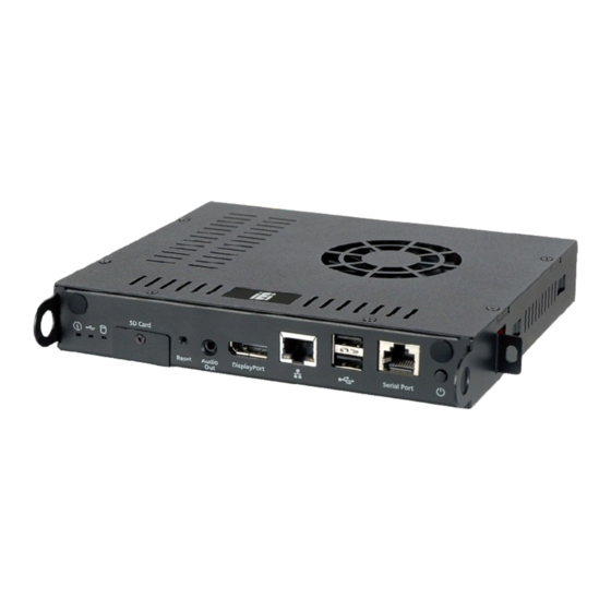
Page 14: Rear Panel
IOPS-Q67/H61 Pluggable Module PC Figure 1-2: Front Panel 1.4.2 Rear Panel The rear panel of the IOPS-Q67/H61 contains an OPS compliant JAE connector which can connected with OPS displays. An overview of the rear panel is shown in F igure 1-3. -
Page 15: Bottom Panel
Before removing the SO-DIMM access panel, make sure the system has been turned off and all power connectors unplugged. The bottom panel of the IOPS-Q67/H61 contains a removable cover to access the SO-DIMM. Figure 1-4: Bottom Panel... -
Page 16: Technical Specifications
IOPS-Q67/H61 Pluggable Module PC 1.5 Technical Specifications The specifications for the Intel based embedded systems are listed below. IOPS-Q67-i5-4GB IOPS-H61-C-4GB 2.70GHz Intel® Core™ i5-2390T 2.40GHz Intel® Celeron® G530 dual-core CPU (3M cache) dual-core CPU (2M cache) System Chipset Intel® Q67 Express Chipset Intel®... -
Page 17: Table 1-2: Technical Specifications
IOPS-Q67/H61 Pluggable Module PC 12 V @ 3.83 A (Intel® Celeron® G530 with 4 GB DDR3 memory) Power Consumption Operating Temperature 0ºC ~ 45ºC -10 ºC ~ 55ºC Storage Temperature Color Black Windows 7 or Windows Embedded Standard 7 Supported OS... -
Page 18: Dimensions
IOPS-Q67/H61 Pluggable Module PC 1.6 Dimensions The physical dimensions of the IOPS-Q67/H61 embedded systems are shown in F igure 1-5. Height: 30.00 mm Width: 200.00 mm Length: 171.00 mm Figure 1-5: IOPS-Q67/H61 Dimensions (mm) Page 8... -
Page 19: Unpacking
IOPS-Q67/H61 Pluggable Module PC Chapter Unpacking Page 9... -
Page 20: Anti-Static Precautions
Follow the anti-static precautions outlined in Section 2.1. Make sure the packing box is facing upwards so the IOPS-Q67/H61 does not fall out of the box. Make sure all the components shown in Section 2.3 are present. ... -
Page 21: Unpacking Checklist
If some of the components listed in the checklist below are missing, please do not proceed with the installation. Contact the IEI reseller or vendor you purchased the IOPS-Q67/H61 from or contact an IEI sales representative directly. To contact an IEI sales representative, please send an email to sales@ieiworld.com. -
Page 22: Installation
IOPS-Q67/H61 Pluggable Module PC Chapter Installation Page 12... -
Page 23: Installation Precautions
Electric shock and personal injury might occur if the rear panel of the IOPS-Q67/H61 is opened while the power cord is still connected to an electrical outlet. -
Page 24: Sd Card Installation
3.2 SD Card Installation The IOPS-Q67/H61 series has a SDHC card slot on the front panel. To install the SDHC card into the system, please follow the steps below. -
Page 25: Pluggable Module Installation
IOPS-Q67/H61 Pluggable Module PC 3.3 Pluggable Module Installation To install the IOPS-Q67/H61 to an OPS compliant display, following the steps below. Align the IOPS-Q67/H61 pluggable module with the OPS slot of the display. Step 1: Push the IOPS-Q67/H61 into the bottom (Figure 3-3). -
Page 26: Audio Line-Out Connector
IOPS-Q67/H61 Pluggable Module PC To install these devices, connect the corresponding cable connector from the actual device to the corresponding IOPS-Q67/H61 external peripheral interface connector making sure the pins are properly aligned. 3.4.1 Audio Line-out Connector CN Label: Audio out... -
Page 27: Ops Connector
IOPS-Q67/H61 Pluggable Module PC Figure 3-4: RJ-45 Ethernet Connector The RJ-45 Ethernet connector has two status LEDs, one green and one yellow. The green LED indicates activity on the port and the yellow LED indicates the port is linked. See Table 3-2. -
Page 28: Table 3-3: Ops Connector (Jae1) Pinouts
IOPS-Q67/H61 Pluggable Module PC PIN NO. DESCRIPTION PIN NO. DESCRIPTION DDP_0P UART_RXD UART_TXD DDP_AUXN DDP_AUXP USB3_SSRX- DDP_HPD USB3_SSRX+ TMDS_CLK- USB3_SSTX- TMDS_CLK+ USB3_SSTX+ TMDS_0- USB2_PN2 TMDS_0+ USB2_PP2 TMDS_1- USB2_PN1 TMDS_1+ USB2_PP2 TMDS_2- USB2_PN0 TMDS_2+ USB2_PP0 DDC_DATA Lineout_L DDC_CLK Lineout_R HDMI_HPD HDMI_CEC... -
Page 29: Rs-232 Serial Port Connector
IOPS-Q67/H61 Pluggable Module PC 3.4.5 RS-232 Serial Port Connector CN Label: Serial Port RJ-45 CN Type: See Table 3-4 CN Pinouts: The RS-232 serial port connector allows connection to a serial device. Description Description SOUT Table 3-4: Serial Port Pinouts... -
Page 30: Usb 2.0 Connectors
IOPS-Q67/H61 Pluggable Module PC Figure 3-6: RJ-45 Serial Port Connection Secure the connector. Secure the serial device connector to the external Step 4: interface by tightening the two retention screws on either side of the connector. 3.4.6 USB 2.0 Connectors CN Label: USB 2.0 port... -
Page 31: Driver Installation
IOPS-Q67/H61 Pluggable Module PC 3.5 Driver Installation NOTE: The content of the CD may vary throughout the life cycle of the product and is subject to change without prior notice. Visit the IEI website or contact technical support for the latest updates. -
Page 32: Bios Screens
IOPS-Q67/H61 Pluggable Module PC Chapter BIOS Screens Page 22... -
Page 33: Introduction
IOPS-Q67/H61 Pluggable Module PC 4.1 Introduction The BIOS is programmed onto the BIOS chip. The BIOS setup program allows changes to certain system settings. This chapter outlines the options that can be changed. 4.1.1 Starting Setup The UEFI BIOS is activated when the computer is turned on. The setup program can be activated in one of two ways. -
Page 34: Getting Help
IOPS-Q67/H61 Pluggable Module PC Function Esc key Main Menu – Quit and not save changes into CMOS Status Page Setup Menu and Option Page Setup Menu -- Exit current page and return to Main Menu General help, only for Status Page Setup Menu and Option... -
Page 35: Main
IOPS-Q67/H61 Pluggable Module PC 4.2 Main The Main BIOS menu (BIOS Menu 1) appears when the BIOS Setup program is entered. The Main menu gives an overview of the basic system information. Aptio Setup Utility – Copyright (C) 2011 American Megatrends, Inc. -
Page 36: Advanced
IOPS-Q67/H61 Pluggable Module PC The System Overview field also has two user configurable fields: System Date [xx/xx/xx] Use the System Date option to set the system date. Manually enter the day, month and year. System Time [xx:xx:xx] Use the System Time option to set the system time. Manually enter the hours, minutes and seconds. -
Page 37: Cpu Configuration
IOPS-Q67/H61 Pluggable Module PC 4.3.1 CPU Configuration Use the CPU Configuration menu (BIOS Menu 3) to enter the CPU Information submenu or enable Intel Virtualization Technology. Aptio Setup Utility – Copyright (C) 2011 American Megatrends, Inc. Advanced CPU Configuration Socket specific CPU Information >... -
Page 38: Bios Menu 4: Cpu Configuration
IOPS-Q67/H61 Pluggable Module PC Aptio Setup Utility – Copyright (C) 2011 American Megatrends, Inc. Advanced CPU Configuration Intel(R) Celeron(R) CPU G530 @ 2.40GHz CPU Signature 206a7 ---------------------- Microcode Patch : Select Screen Max CPU Speed 2400 MHz : Select Item... -
Page 39: Usb Configuration
IOPS-Q67/H61 Pluggable Module PC 4.3.2 USB Configuration Use the USB Configuration menu (BIOS Menu 5) to read USB configuration information and configure the USB settings. Aptio Setup Utility – Copyright (C) 2011 American Megatrends, Inc. Advanced USB Configuration USB Support Parameters... -
Page 40: H/W Monitor
IOPS-Q67/H61 Pluggable Module PC keyboard can control the system even when there is no USB driver loaded onto the system. Legacy USB support enabled Enabled EFAULT Legacy USB support disabled Disabled Legacy USB support disabled if no USB devices are... -
Page 41: Chipset
IOPS-Q67/H61 Pluggable Module PC VCC3V V_CORE V_1.05 V_MEM VSB3 VBAT 5VSB CPU Smart Fan control [Enabled] Use the CPU Smart Fan control option to disable or enable the CPU Smart Fan. The CPU smart fan is enabled. Enabled EFAULT ... - Page 42 IOPS-Q67/H61 Pluggable Module PC IGD Memory [128 M] Use the IGD Memory option to specify the amount of system memory that can be used by the Internal graphics device. Disable 32 MB of memory used by internal graphics device 32 M ...
- Page 43 IOPS-Q67/H61 Pluggable Module PC 480 MB of memory used by internal graphics 480 M device 512 MB of memory used by internal graphics 512 M device 1024 MB of memory used by internal graphics 1024 M device ...
-
Page 44: Boot
IOPS-Q67/H61 Pluggable Module PC 4.5 Boot Use the Boot menu (BIOS Menu 8) to configure system boot options. Aptio Setup Utility – Copyright (C) 2011 American Megatrends, Inc. Main Advanced Chipset Boot Security Save & Exit Boot Configuration Select the keyboard... -
Page 45: Security
IOPS-Q67/H61 Pluggable Module PC 4.6 Security Use the Security menu (BIOS Menu 9) to set system and user passwords. Aptio Setup Utility – Copyright (C) 2011 American Megatrends, Inc. Main Advanced Chipset Boot Security Save & Exit Password Description Set Setup Administrator Password If ONLY the Administrator’s password is set,... -
Page 46: Exit
IOPS-Q67/H61 Pluggable Module PC 4.7 Exit Use the Exit menu (BIOS Menu 10) to load default BIOS values, optimal failsafe values and to save configuration changes. Aptio Setup Utility – Copyright (C) 2011 American Megatrends, Inc. Main Advanced Chipset Boot Security Save &... - Page 47 IOPS-Q67/H61 Pluggable Module PC Save as User Defaults Use the Save as User Defaults option to save the changes done so far as user defaults. Restore User Defaults Use the Restore User Defaults option to restore the user defaults to all the setup options.
-
Page 48: Maintenance
IOPS-Q67/H61 Pluggable Module PC Chapter Maintenance Page 38... -
Page 49: System Maintenance Overview
Failure to follow these instructions may lead to personal injury and system damage. To preserve the working integrity of the IOPS-Q67/H61, the system must be properly maintained. If internal components need replacement, the proper maintenance procedures must be followed to ensure the system can continue to operate normally. -
Page 50: Msata Replacement
(see Section 5.2.1) 5.2.1 mSATA Replacement The IOPS-Q67/H61 is preinstalled with one mSATA module. To replace the mSATA module, please refer to the diagram and instructions below. Open the system cover by removing the retention screws shown on Figure Step 1: 5-1. -
Page 51: Figure 5-2: Pcie Mini Card Slot Location
IOPS-Q67/H61 Pluggable Module PC Figure 5-2: PCIe Mini Card Slot Location Remove the mSATA module. Push the two spring clips in to release the Step 3: mSATA module. Insert a new mSATA module into the socket at an angle. Line up the notch Step 4: on the card with the notch on the connector. -
Page 52: So-Dimm Replacement
IOPS-Q67/H61. To replace a SO-DIMM memory module into a SO-DIMM socket, please follow the steps below. Remove the SO-DIMM access panel. Place the IOPS-Q67/H61 on an Step 1: anti-static pad with the bottom panel facing up. Remove the SO-DIMM access panel retention screw shown in Figure 5-4. -
Page 53: Figure 5-5: So-Dimm Removal
IOPS-Q67/H61 Pluggable Module PC Remove the SO-DIMM by releasing the arms on the SO-DIMM socket. ( Step 3: F igure 5-5). Figure 5-5: SO-DIMM Removal Align the new SO-DIMM with the socket. The SO-DIMM must be oriented in Step 4:... -
Page 54: Interface Connectors
IOPS-Q67/H61 Pluggable Module PC Chapter Interface Connectors Page 44... -
Page 55: Peripheral Interface Connectors
IOPS-Q67/H61 Pluggable Module PC 6.1 Peripheral Interface Connectors The IOPS-Q67/H61 series’ motherboard comes with a number of peripheral interface connectors and configuration jumpers. The connector locations are shown in Figure 6-1 and Figure 6-2. The Pin 1 locations of the on-board connectors are also indicated in the diagrams below. -
Page 56: Internal Peripheral Connectors
Internal peripheral connectors are found on the motherboard and are only accessible when the motherboard is outside of the chassis. The table below shows a list of the peripheral interface connectors on the IOPS-Q67/H61 motherboard. Pinouts of these connectors can be found in the following sections. -
Page 57: Battery Connector (Bt1)
IOPS-Q67/H61 Pluggable Module PC Connector Type Label PCIe Mini card slots Full-size PCIe Mini card slot SD card slot SD card slot SO-DIMM connector SO-DIMM connector DIMM1 USB DOM connector 8-pin header USB2 Table 6-1: Peripheral Interface Connectors 6.2.1 Battery Connector (BT1) PIN NO. -
Page 58: Half-Size Pcie Mini Slot (Jp1)
IOPS-Q67/H61 Pluggable Module PC 6.2.4 Half-Size PCIe Mini Slot (JP1) PIN NO. DESCRIPTION PIN NO. DESCRIPTION PCIE-WAKE +3.3V +1.5V PCIE_CLK- PCIE_CLK+ RESET +3.3V RESET PCIE_RN4 +3.3V PCIE_RP4 +1.5V SMB_CLK PCIE_TN4 SMB_DATA PCIE_TP4 -USBP +USBP +3.3V +3.3V +1.5V +3.3V Table 6-5: Half-Size PCIe Mini Card Slot (JP1) Pinouts... -
Page 59: Full-Size Pcie Mini Slot (Jp2)
IOPS-Q67/H61 Pluggable Module PC 6.2.5 Full-Size PCIe Mini Slot (JP2) PIN NO. DESCRIPTION PIN NO. DESCRIPTION +3.3V SATA_RXP +3.3V SATA_TXP SATA_TXN SATA_TXP +3.3V +3.3V +3.3V Table 6-6: Full-Size PCIe Mini Card Slot (JP2) Pinouts Page 49... -
Page 60: Usb Dom Connector (Usb2)
IOPS-Q67/H61 Pluggable Module PC 6.2.6 USB DOM Connector (USB2) PIN NO. DESCRIPTION DATA- DATA+ Table 6-7: USB DOM Connector (USB2) Pinouts Page 50... -
Page 61: A Safety Precautions
IOPS-Q67/H61 Pluggable Module PC Appendix Safety Precautions Page 51... -
Page 62: Safety Precautions
IOPS-Q67/H61 is being installed, moved or modified. Do not apply voltage levels that exceed the specified voltage range. Doing so may cause fire and/or an electrical shock. Electric shocks can occur if the IOPS-Q67/H61 chassis is opened when the IOPS-Q67/H61 is running. ... -
Page 63: Anti-Static Precautions
Electrostatic discharge (ESD) can cause serious damage to electronic components, including the IOPS-Q67/H61. Dry climates are especially susceptible to ESD. It is therefore critical that whenever the IOPS-Q67/H61 is opened and any of the electrical components are handled, the following anti-static precautions are strictly adhered to. -
Page 64: Product Disposal
Please follow the national guidelines for electrical and electronic product disposal. A.2 Maintenance and Cleaning Precautions When maintaining or cleaning the IOPS-Q67/H61, please follow the guidelines below. A.2.1 Maintenance and Cleaning Prior to cleaning any part or component of the IOPS-Q67/H61, please read the details below. Page 54... -
Page 65: Cleaning Tools
Some components in the IOPS-Q67/H61 may only be cleaned using a product specifically designed for the purpose. In such case, the product will be explicitly mentioned in the cleaning tips. Below is a list of items to use when cleaning the IOPS-Q67/H61. ... -
Page 66: Bbios Menu Options
IOPS-Q67/H61 Pluggable Module PC Appendix BIOS Menu Options Page 56... -
Page 67: Bios Configuration Options
IOPS-Q67/H61 Pluggable Module PC B.1 BIOS Configuration Options Below is a list of BIOS configuration options described in Chapter 5. System Overview .........................25 Memory Information ......................25 System Date [xx/xx/xx] ......................26 System Time [xx:xx:xx] .......................26 Intel Virtualization Technology [Disabled] ................27 ... -
Page 68: C Watchdog Timer
IOPS-Q67/H61 Pluggable Module PC Appendix Watchdog Timer Page 58... - Page 69 IOPS-Q67/H61 Pluggable Module PC NOTE: The following discussion applies to DOS environment. IEI support is contacted or the IEI website visited for specific drivers for more sophisticated operating systems, e.g., Windows and Linux. The Watchdog Timer is provided to ensure that standalone systems can always recover from catastrophic conditions that cause the CPU to crash.
-
Page 70: Example Program
IOPS-Q67/H61 Pluggable Module PC NOTE: When exiting a program it is necessary to disable the Watchdog Timer, otherwise the system resets. Example program: ; INITIAL TIMER PERIOD COUNTER W_LOOP: AX, 6F02H ;setting the time-out value BL, 30 ;time-out value is 48 seconds ;...
Need help?
Do you have a question about the IOPS-Q67/H61 and is the answer not in the manual?
Questions and answers