Sign In
Upload
Manuals
Brands
IEI Technology Manuals
Desktop
ITG-100AI
IEI Technology ITG-100AI Manuals
Manuals and User Guides for IEI Technology ITG-100AI. We have
1
IEI Technology ITG-100AI manual available for free PDF download: User Manual
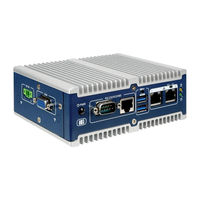
IEI Technology ITG-100AI User Manual (88 pages)
Fanless Embedded System with Intel Atom x5-E3930, VGA, GbE, Two RS0232/422/485 Two USB 3.0 and RoHS Compliant
Brand:
IEI Technology
| Category:
Desktop
| Size: 4 MB
Table of Contents
Table of Contents
5
1 Introduction
11
Overview
12
Features
12
Figure 1-1: ITG-100AI
12
Technical Specifications
13
Side Panel
14
Table 1-1: Technical Specifications
14
Front Panel
15
Figure 1-2: ITG-100AI Side Panel
14
Figure 1-3: ITG-100AI Front Panel
15
Physical Dimensions
16
Figure 1-4: Physical Dimensions (MM)
16
2 Unpacking
17
Unpacking
18
Packing List
18
Table 2-1: Package List Contents
19
3 Installation
20
Anti-Static Precautions
21
Installation Precautions
21
Bottom Cover Removal and Re-Installation
22
Figure 3-1: Bottom Cover Retention Screws
22
So-DIMM Installation
23
Figure 3-2: Bottom Cover Installation
23
Figure 3-3: SO-DIMM Socket
24
Figure 3-4: SO-DIMM Installation
24
Wireless LAN Module Installation (Optional)
25
Figure 3-5: Accelerator Card Retention Screws
25
Figure 3-6: WLAN M.2 Card Slot Location
26
Figure 3-7: Inserting the WLAN Card into the Slot at an Angle
26
Rs-232/422/485 Serial Port Connection
27
Figure 3-8: Securing the WLAN Card
27
RS-232/422/485 Serial Port Connection
28
Figure 3-9: Serial Device Connector
28
Figure 3-10: DB-9 RS-232/422/485 Serial Port Connector
28
Table 3-1: RJ-45 RS-232/422/485 Serial Port Pinouts
29
Figure 3-11: Serial Device Connector
29
Figure 3-12: RJ-45 RS-232/422/485 Serial Port Connector
29
Table 3-2: DB-9 RS-232/422/485 Connector Pinouts
30
At/Atx Mode Selection
31
AT Power Mode
31
Figure 3-13: DB-9 RS-232/422/485 Connector Pinout Location
30
Figure 3-14: AT/ATX Switch Location
31
ATX Power Mode
32
Mounting the System
32
Figure 3-15: Mounting the DIN Rail
33
Figure 3-16: Mounting to DIN Rail
33
Figure 3-17: Power Button Location
34
Figure 3-18: Reset Button Location
34
Powering On/Off the System
34
Reset the System
34
4 Bios
35
Introduction
36
Starting Setup
36
Using Setup
36
BIOS Menu Bar
37
Getting Help
37
Unable to Reboot after Configuration Changes
37
Table 4-1: BIOS Navigation Keys
37
BIOS Menu 1: Main
38
Advanced
39
Main
38
BIOS Menu 2: Advanced
39
System Date [XX/XX/XX]
39
System Time [XX:XX:XX]
39
ACPI Settings
40
BIOS Menu 3: ACPI Configuration
40
ACPI Sleep State [S3 Only (Suspend to RAM)]
40
F81866 Super IO Configuration
41
Serial Port N Configuration
41
BIOS Menu 4: Super IO Configuration
41
BIOS Menu 5: Serial Port 1 Configuration Menu
41
Serial Port [Enabled]
41
Device Mode [RS232]
41
Serial Port [Enabled]
42
Device Mode [RS232]
42
Hardware Monitor
43
RTC Wake Settings
44
BIOS Menu 6: Hardware Monitor
44
PC Health Status
44
BIOS Menu 7: RTC Wake Settings
45
Wake System with Fixed Time [Disabled]
45
Console Redirection Settings
46
Serial Port Console Redirection
46
BIOS Menu 8: Serial Port Console Redirection
46
Console Redirection [Disabled]
46
BIOS Menu 9: Console Redirection Settings
47
Terminal Type [ANSI]
47
Bits Per Second [115200]
47
Data Bits [8]
47
Parity [None]
47
Stop Bits [1]
47
CPU Configuration
49
BIOS Menu 10: CPU Configuration
49
Intel Virtualization Technology [Disabled]
49
EIST [Enabled]
49
C-States [Disabled]
49
USB Configuration
50
BIOS Menu 11: USB Configuration
50
USB Devices
50
Legacy USB Support [Enabled]
50
Iei Feature
51
BIOS Menu 12: Iei Feature
51
Auto Recovery Function [Disabled]
51
SATA Configuration
52
BIOS Menu 13: IDE Configuration
52
SATA Mode Selection [AHCI]
52
Hot Plug [Disabled]
52
Chipset
53
BIOS Menu 14: Chipset
53
North Bridge Configuration
54
Intel IGD Configuration
54
BIOS Menu 15: Northbridge Chipset Configuration
54
Memory Information
54
BIOS Menu 16: Integrated Graphics
55
Primary Display [IGD]
55
DVMT Pre-Allocated [256MB]
55
DVMT Total Gfx Mem [Max]
55
Southbridge Configuration
56
BIOS Menu 17: Southbridge Chipset Configuration
56
Restore AC Power Loss [Last State]
56
Power Saving Function (EUP) [Disabled]
56
OS Selection [Windows]
56
PCI Express Configuration
57
BIOS Menu 18: PCI Express Configuration
57
Compliance Mode [Disabled]
57
SCC Configuration
58
BIOS Menu 19: PCI Express Configuration
58
Pcie Speed [Auto]
58
SCC SD Card Support [Enabled]
58
Security
59
BIOS Menu 20: Security
59
Emmc Max Speed [HS400]
59
Administrator Password
59
User Password
59
Boot
60
BIOS Menu 21: Boot
60
Bootup Numlock State [On]
60
Quiet Boot [Enabled]
60
Launch PXE Oprom [Disabled]
60
Option ROM Messages [Force BIOS]
60
UEFI Boot [Disabled]
61
Exit
62
BIOS Menu 22:Exit
62
Boot Option Priority
62
Hard Drive BBS Priorities
62
Save Changes and Reset
62
Discard Changes and Reset
62
Restore Defaults
62
Save as User Defaults
62
Restore User Defaults
62
5 Software Installation
64
Available Drivers
65
Driver Download
65
Figure 5-1: IEI Resource Download Center
65
Openvino™ Toolkit Installation
67
A Regulatory Compliance
68
B Safety Precautions
73
Safety Precautions
74
B.1 S Afety P Recautions
74
General Safety Precautions
74
Anti-Static Precautions
75
Product Disposal
76
Maintenance and Cleaning Precautions
77
B.2 M Aintenance and C Leaning P Recautions
77
Cleaning Tools
77
Maintenance and Cleaning
77
CBIOS Menu Options
79
Itg-100Ai Embedded System
80
D Terminology
82
E Hazardous Materials Disclosure
86
Advertisement
Advertisement
Related Products
IEI Technology IBX-700 Series
IEI Technology IOVU-07F-AD
IEI Technology IOPS-Q67/H61
IEI Technology IVS-300
IEI Technology IVS-200-ULT2
IEI Technology ITCS-100-H81
IEI Technology IDS-310-AL
IEI Technology IDS-310AI
IEI Technology IDS-310AI-AL-J1/8GB-R10
IEI Technology ITG-100-AL
IEI Technology Categories
Motherboard
Touch Panel
Computer Hardware
Single board computers
Desktop
More IEI Technology Manuals
Login
Sign In
OR
Sign in with Facebook
Sign in with Google
Upload manual
Upload from disk
Upload from URL