
Related Manuals for IEI Technology JUKI- 740E


Summary of Contents for IEI Technology JUKI- 740E
-
Page 1: User Manual
JUKI- 740E User Manual Version 4.0 ® Pentium with LCD/CRT & Ethernet PCISA Bus Single Board Computer February 10, 2004 ©Copyright 2004 by ICP Electronics Inc. All Rights Reserved. -
Page 2: Copyright Notice
Copyright Notice The information in this document is subject to change without prior notice in order to improve reliability, design and function and does not represent a commitment on the part of the manufacturer. In no event will the manufacturer be liable for direct, indirect, special, incidental, or consequential damages arising out of the use or inability to use the product or documentation, even if advised of the possibility of such damages. -
Page 3: Table Of Contents
TABLE OF CONTENTS CHAPTER 1. INTRODUCTION............4 ................5 PECIFICATIONS ................6 ACKAGE ONTENTS CHAPTER 2. INSTALLATION ............7 JUKI-740E L ...............7 AYOUT CPU S JUKI-740E ............8 ETTINGS OF ................ 10 ATCH IMER ™ F ............. 10 LASH LCD V ..............11 OLTAGE ETTING CMOS S... -
Page 4: Chapter 1. Introduction
Chapter 1. Introduction Thank you for choosing JUKI-740E Pentium® with HiQPro™ LCD/CRT and Ethernet Single Board Computer. The JUKI-740E board is an PCISA form factor board, which comes equipped with high performance Pentium® CPU and advanced high performance multi-mode I/O, designed for the system manufacturers, integrators, or VARs that want to provide all the performance, reliability, and quality at a reasonable price. -
Page 5: Specifications
1.1 Specifications The JUKI-740E Pentium® with HiQPro™ LCD/CRT & Ethernet Single Board Computer provides the following specification: CPU : Pentium® MMX up to 233Mhz, AMD K6 processor up to 300MHz, Cyrix 6x86MX and IDE C6 processor PCISA Bus : ISA bus and PCI 32-bit local bus, PCI 2.1 standard Chipset : ALI M1531/M1543 LCD/CRT Interface : : C&T 69000 Chipset CRT Resolution :... -
Page 6: Package Contents
1.2 Package Contents In addition to this User's Manual, the JUKI-740E package includes the following items: JUKI-740E Pentium® with HiQPro™ LCD/CRT & Ethernet Single Board Computer RS-232/Printer Cable FDD/HDD Cable 6-pin Mini-Din to 5-pin Din Keyboard and Mouse Adapter Cable If any of these items is missing or damaged, contact the dealer from whom you purchased the product. -
Page 7: Chapter 2. Installation
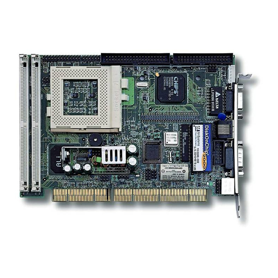
Chapter 2. Installation This chapter describes how to install the JUKI-740E. First, the layout of JUKI- 740E is shown, and then the unpacking information that you should pay attention to is described. Other information such as jumper and switch settings for the JUKI-740E's configuration, such as CPU type selection, system clock setting, and watch dog timer, are also included. -
Page 8: Cpu Settings Of Juki-740E
2.2 CPU Settings of JUKI-740E CPU Clock Setting : CPU Speed/Clock 9-10 11-12 55MHz SHORT SHORT OPEN 60MHz SHORT OPEN OPEN 66MHz OPEN OPEN OPEN CPU to Bus Multiple : Multiplier 1.5 x OPEN OPEN OPEN SHORT OPEN OPEN 2.5x SHORT SHORT OPEN... - Page 9 JP1 CPU Core Voltage Setting : (JP1 is in the power module) CPU Core Voltage 3.5V(P54C/CS) SHORT SHORT SHORT SHORT 3.4V(P54C/CS) OPEN SHORT SHORT SHORT 3.3V SHORT OPEN SHORT SHORT 3.2V OPEN OPEN SHORT SHORT 3.1V SHORT SHORT OPEN SHORT 3.0V OPEN SHORT...
-
Page 10: Watch-Dog Timer
AMD K6 MMX Rating Table, dual voltage Core Product Name Vcore Bus MHz Multiplier Freq K6-233 model 6 233MHz 3.2V 3.5x K6-200 model 6 200MHz 2.9V K6-166 model 6 166MHz 2.9V 2.5x K6-300 model 7 300MHz 2.2V 4.5x K6-266 model 7 266MHz 2.2V K6-233 model 7 233MHz 2.2V... -
Page 11: Lcd Voltage Setting
2.5 LCD Voltage Setting The JUKI-740E supports 3.3V or 5V LCD panel via different jumper settings and these settings will modify CN3’s Pin 29 & 30 to 3.3V or 5V output. JP39 : LCD Voltage Setting FUNCTION JP39 3.3V 2.6 Clear CMOS Setup If users want to clear the CMOS Setup(for example when you have forgotten the password, then what you should do is to clear setup and reset the password), you should short CN34 pin 2-3 for about 3 seconds, then open it again. -
Page 12: On Board Lan Setup
2.9 On Board LAN Setup Configuring JP3 to open or short will Enabled / Disabled onboard LAN. JP3 : LCD Voltage Setting Function 1-2 OPEN LAN Disabled 1-2 SHORT LAN Enabled... -
Page 13: Chapter 3. Connection
Chapter 3. Connection This chapter describes how to connect peripherals, switches and indicators to the JUKI-740E board. Floppy Disk Drive Connector JUKI-740E board is equipped with a 34-pin daisy-chain driver connector cable. CN25 : FDC CONNECTOR DESCRIPTION DESCRIPTION GROUND REDUCE WRITE GROUND GROUND GROUND... -
Page 14: Pci E-Ide Disk Drive Connector
3.2 PCI E-IDE Disk Drive Connector You can attach up to four IDE( Integrated Device Electronics) hard disk drives to the JUKI-740E IDE controller. IDE also supports Ultra DMA/33 interface. CN21 : Primary IDE Connector CN21: IDE Interface Connector DESCRIPTION DESCRIPTION RESET# GROUND... -
Page 15: Serial Ports
Serial Ports The JUKI-740E offers two high speed NS16C550 compatible UARTs with Read/Receive 16 byte FIFO serial ports. CN27 : Serial Port DB-9 Connector( COM1 ) DESCRIPTION DATA CARRIER DETECT (DCD) RECEIVE DATA (RXD) TRANSMIT DATA (TXD) DATA TERMINAL READY (DTR) GROUND (GND) -
Page 16: External Switches And Indicators
CN36 : 6-pin Mini-DIN Keyboard Connector DESCRIPTION KEYBOARD DATA MOUSE DATA GROUND KEYBOARD CLOCK MOUSE CLOCK 3.6 External Switches and Indicators There are many external switches and indicators for monitoring and controlling your CPU board. CN2: Speaker Connector DESCRIPTION Speaker Signal CN38 : Reset Connector DESCRIPTION External Reset... -
Page 17: Lcd/Crt Connector
3.8 LCD/CRT Connector The JUKI-740E has a built-in 15-pin VGA connector that allows direct connection to your CRT monitor. There is also a built-in 50-pin connector to support LCD interface. CN29 : 15-pin Female Connector GREEN BLUE GROUND GROUND GROUND GROUND GROUND DDDA... - Page 18 CN39 LED Connector(2-pin header) for LAN 10Mbps 100Mbps Active...
-
Page 19: Chapter 4. Ami Bios Setup
Chapter 4. AMI BIOS Setup The JUKI-740E uses the AMI BIOS for system configuration. The AMI BIOS setup program is designed to provide maximum flexibility in configuring the system through offering various options which may be selected to meet end-users’ variety of needs. -
Page 20: Advanced Chipset Setup
4.4 Advanced Chipset Setup The functions in this page are mostly related to ChipSet (ALI 4+). These options are used to change the ChipSet‘s registers. Please be extra careful in making any changes to the default settings, otherwise system could become unstable. Auto Configuration : Enable or Disable When using 60nS general type DRAM, please enable the setting so as to get optimal timings. -
Page 21: Power Management Setup
4.6 Power Management Setup Power Management Setup help users to administer JUKI-740E board’s “green” function. The features in this configuration page could shut down video display and hard disk to save energy. For example, in Power Management/APM, you have Disable, Max Saving, Min Saving, or User Defined four options to choose from. -
Page 22: Appendix A. Watch-Dog Timer
Appendix A. Watch-Dog Timer The Watch-Dog Timer is provided to ensure that standalone systems can always recover from catastrophic conditions that caused the CPU to crash. This condition may have occurred due to external EMI or a software bug. When the CPU stops working correctly, onboard hardware will either perform a hardware reset (cold boot) or a non-maskable interrupt (NMI) to bring the system back to a known state. -
Page 23: Appendix B. Fp24-01 Flat Panel Connection Module
Appendix B. FP24-01 Flat Panel Connection Module The FP24-01 connection module is installed on the JUKI-740E as a standard product feature. FP24-01 converts JUKI-740E’s on board 50pin LCD interface signal to the 44-pin (2x20 pin header) and 41pin (Hirose DF9-41P-1V) LCD connectors. - Page 24 J2 : LCD Backlight Power Connector DESCRIPTION 3.3V or 5V FPVEE Inverter Enable...
Need help?
Do you have a question about the JUKI- 740E and is the answer not in the manual?
Questions and answers