Table of Contents
Advertisement
Quick Links
Advertisement
Table of Contents
Troubleshooting

Related Manuals for IEI Technology ECK-1000 Series


Summary of Contents for IEI Technology ECK-1000 Series
- Page 1 ECK-1000 Embedded System Page i...
- Page 2 ECK-1000 Embedded System Revision Date Version Changes December 2007 1.00 Initial release Page ii...
- Page 3 ECK-1000 Embedded System Copyright COPYRIGHT NOTICE The information in this document is subject to change without prior notice in order to improve reliability, design and function and does not represent a commitment on the part of the manufacturer. In no event will the manufacturer be liable for direct, indirect, special, incidental, or consequential damages arising out of the use or inability to use the product or documentation, even if advised of the possibility of such damages.
- Page 4 ECK-1000 Embedded System Manual Conventions WARNING! Warnings appear where overlooked details may cause damage to the equipment or result in personal injury. Warnings should be taken seriously. Warnings are easy to recognize. The word “warning” is written as “WARNING,” both capitalized and bold and is followed by text.
- Page 5 ECK-1000 Embedded System CAUTION: This is an example of a caution message. Failure to adhere to cautions messages may result in permanent damage to the ECK-1000. Please take caution messages seriously. NOTE: These messages inform the reader of essential but non-critical information. These messages should be read carefully as any directions or instructions contained therein can help avoid making mistakes.
- Page 6 ECK-1000 Embedded System Packing List NOTE: If any of the components listed in the checklist below are missing, please do not proceed with the installation. Contact the IEI reseller or vendor you purchased the ECK-1000 from or contact an IEI sales representative directly.
-
Page 7: Table Of Contents
ECK-1000 Embedded System Table of Contents INTRODUCTION..................... 1 1.1 I ......................2 NTRODUCTION 1.1.1 ECK-1000 Models....................2 1.1.2 ECK-1000 Benefits..................... 3 1.1.3 ECK-1000 Features ................... 3 1.2 ECK-1000 O ....................3 VERVIEW 1.2.1 ECK-1000 Overview Photo................3 1.2.2 ECK-1000 Peripheral Connectors and Jumpers ..........4 1.2.3 Technical Specifications.................. - Page 8 ECK-1000 Embedded System 3.2.1 Package Contents..................... 20 INSTALLATION ....................23 4.1 A ..................24 STATIC RECAUTIONS 4.2 I ..................24 NSTALLATION ROCEDURE 4.2.1 Unpacking ......................25 4.2.2 Top Cover Removal ..................26 4.2.3 Motherboard Removal ..................26 4.2.4 CPU Installation ....................28 4.2.5 Cooling Kit Installation ...................
- Page 9 ECK-1000 Embedded System 4.2.16 Power On ....................... 55 BIOS SETTINGS AND DRIVER INSTALLATION........... 57 TROUBLESHOOTING AND MAINTENANCE ..........59 6.1 ECK-1000 S ............60 YSTEM AINTENANCE VERVIEW 6.2 S ..................60 YSTEM ROUBLESHOOTING 6.2.1 The System Doesn’t Turn On ................60 6.2.2 The System Doesn’t Boot Up................
- Page 10 ECK-1000 Embedded System List of Figures Figure 1-1: ECK-1000........................2 Figure 1-2: ECK-1000 Overview [Front View]................4 Figure 1-3: ECK-1000 Overview [Rear View]................4 Figure 2-1: ECK-1000 Dimensions (mm) ..................9 Figure 2-2: KINO SBC Dimensions (mm) ...................10 Figure 2-3: ECK-1000 Front Panel....................10 Figure 2-4: ECK-1000 Rear Panel....................11 Figure 2-5: ECK-1000 Cooling Vents ..................12 Figure 2-6: ECK-1000 Internal Overview ..................13 Figure 2-7: Cooling Fan Dimensions (mm) ................14...
- Page 11 ECK-1000 Embedded System Figure 4-23: COM 3 Function Select Jumper Location.............45 Figure 4-24: VESA Mounting Plate Retention Screws ..............46 Figure 4-25: Audio Connectors ....................47 Figure 4-26: LAN Connection ......................48 Figure 4-27: PS/2 Keyboard/Mouse Connector .................49 Figure 4-28: Serial Device Connector..................50 Figure 4-29: USB Connector......................51 Figure 4-30: DVI Connector ......................52 Figure 4-31: VGA Connector......................53...
- Page 12 ECK-1000 Embedded System List of Tables Table 1-1: Technical Specifications ....................2 Table 1-2: Technical Specifications ....................6 Table 2-1: Cooling Fan Specifications..................15 Table 2-2: ACE-4525AP PSU Specifications................17 Table 3-1: Package List Contents....................21 Table 4-1: Jumpers ........................42 Table 4-2: Clear CMOS Jumper Settings ..................43 Table 4-3: Function Select Jumper Settings ................44 Table 4-4: IEI Provided Cables ....................45 Page xii...
-
Page 13: Introduction
ECK-1000 Embedded System Chapter Introduction Page 1... -
Page 14: Introduction
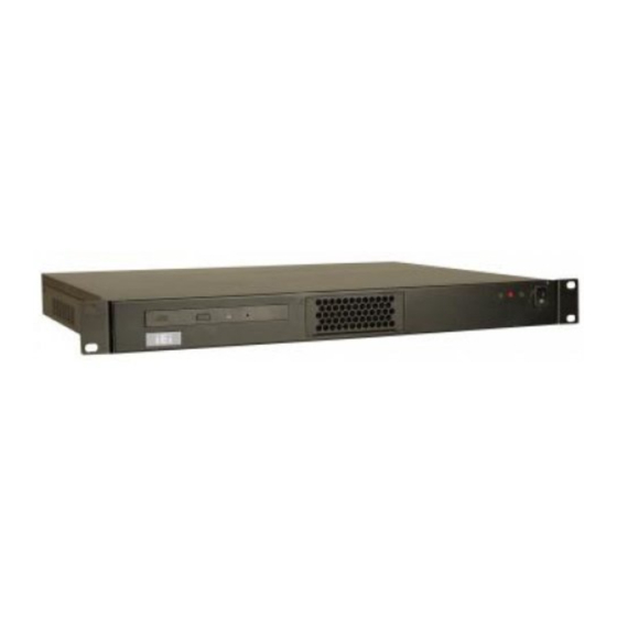
1.1 Introduction Figure 1-1: ECK-1000 The ECK-1000 series integrate a KINO mini-ITX motherboard and a power supply in a 1U chassis. The ECK-1000 is for use with large digital displays like airport information displays or multimedia signage. The ECK-1000 attaches directly to the back of a large display using the optional mounting kit. -
Page 15: Eck-1000 Benefits
ECK-1000 Embedded System 1.1.2 ECK-1000 Benefits Some of the ECK-1000 benefits include: Multiple display options allow two separate video outputs PCI and Mini-PCI slots allow board expansion with PCI and Mini PCI expansion cards Flexible storage options include SATA and IDE hard drives DDR2 enables faster data transfers High speed network access through two PCIe GbE ports Thermal controls enhance voltage efficiency and support cooler and quieter... -
Page 16: Eck-1000 Peripheral Connectors And Jumpers
ECK-1000 Embedded System Figure 1-2: ECK-1000 Overview [Front View] Figure 1-3: ECK-1000 Overview [Rear View] 1.2.2 ECK-1000 Peripheral Connectors and Jumpers The ECK-1000 has the following external peripheral interface connectors: 1 x Power switch 1 x Reset button 1 x CD drive bay 2 x PCI slots 1 x Mic in 1 x Line out... -
Page 17: Technical Specifications
ECK-1000 Embedded System Clear CMOS LVDS voltage selector 1.2.3 Technical Specifications ECK-1000 technical specifications are listed in Table 1-2. See Chapter 2 for details. Specification ECK-1000-9453 ECK-1000-690S1 Intel® Core™2 Duo AMD Turion™ 64 X2 System CPU Intel® Core™ Duo AMD Turion™ 64 Intel®... -
Page 18: Table 1-2: Technical Specifications
ECK-1000 Embedded System Specification ECK-1000-9453 ECK-1000-690S1 Two 240-pin DIMM sockets Two 200-pin SO-DIMM support two dual-channel sockets support two 400MHz, 533MHz or 667MHz dual-channel DDR2 Memory DDR2 DIMMS with a SO-DIMMs with a maximum maximum capacity of 2GB capacity of 1GB each each One 2.5”... -
Page 19: Mechanical Description
ECK-1000 Embedded System Chapter Mechanical Description Page 7... -
Page 20: Mechanical Overview
ECK-1000 Embedded System 2.1 Mechanical Overview The ECK-1000 is made of a metal chassis. The chassis is covered with a top cover and comprises multiple air vents to allow for the free flow of cooling air through the system. The front panel of the chassis contains a power button, reset button, fan access panel and CD drive slot. -
Page 21: Figure 2-1: Eck-1000 Dimensions (Mm)
ECK-1000 Embedded System Figure 2-1: ECK-1000 Dimensions (mm) Page 9... -
Page 22: Motherboard Dimensions
ECK-1000 Embedded System 2.2.2 Motherboard Dimensions The KINO series dimensions are listed below and shown in Figure 2-2. Length: 170.00mm Width: 170.00mm Figure 2-2: KINO SBC Dimensions (mm) 2.3 External Overview 2.3.1 Front Panel The front panel contains buttons, fans and a CD drive bay. See Figure 2-3. Figure 2-3: ECK-1000 Front Panel Page 10... -
Page 23: Front Panel Buttons And Indicators
ECK-1000 Embedded System 2.3.1.1 Front Panel Buttons and Indicators The connectors, indicators and buttons listed in this section are shown in Figure 2-3 above. The front panel also contains the following buttons: 1 x Power Button 1 x Reset Button The front panel also contains the following drive bay: 1 x CD drive bay All the front panel items listed above are shown in Figure 2-3 above. -
Page 24: Cooling Vents
ECK-1000 Embedded System 1 x VGA connector 1 x DVI connector 1 x Mouse connector 1 x Keyboard connector All the rear panel items listed above are shown in Figure 2-4 above. 2.3.3 Cooling Vents WARNING: Never remove the top cover from the chassis while power is still being fed into the system. -
Page 25: Internal Overview
ECK-1000 Embedded System 2.4 Internal Overview The ECK-1000 internal components are listed below: 1 x IEI KINO motherboard 1 x Power supply 2 x System cooling fans 1 x PCI expansion board 1 x Power switch cable 1 x Reset button cable 1 x Power LED 1 x Hard drive activity LED 2 x DIMM/SO-DIMM modules (optional) -
Page 26: Component Specifications
ECK-1000 Embedded System 2.5 Component Specifications 2.5.1 Motherboard Please refer to the relevant motherboard manual for complete motherboard specifications: ECK-1000-9453: refer to the KINO-9453 user manual ECK-1000-690S1: refer to the KINO-690S1 user manual 2.5.2 Cooling Fans The ECK-1000 has two internal cooling fans mounted at the front of the chassis and connected directly to the power module. -
Page 27: Ace-4518Ap Psu Specifications
ECK-1000 Embedded System Specification Details Dimensions 40 mm x 40 mm x 20 mm (L x W x Thickness) Bearing System Ball Bearing Rated Voltage 12.0 V Operating Voltage Range 6.0 V ~ 13.8 V Start-up Voltage 6.0 V 0.12 A (0.144 A Max.) at rated voltage Rated Current Lock Rotor Current 0.25 A with rotor locked... - Page 28 ECK-1000 Embedded System Voltage 90 Vrms ~ 265 Vrms Full Range Frequency 47 Hz ~ 63Hz Input Current 4 A (RMS) @ 115 VAC INPUT 2 A (RMS) @ 230 VAC Inrush 50 A Max for 115 VAC Current 80 A Max for 230 VAC Voltage Min.
-
Page 29: Table 2-2: Ace-4525Ap Psu Specifications
ECK-1000 Embedded System Output Connectors 1 x 20 pin ATX 1 x 4-pin 12V CPU 3 x HDD/CDROM 1 x FDD Table 2-2: ACE-4525AP PSU Specifications Page 17... - Page 30 ECK-1000 Embedded System THIS PAGE IS INTENTIONALLY LEFT BLANK Page 18...
-
Page 31: Unpacking
ECK-1000 Embedded System Chapter Unpacking Page 19... -
Page 32: Unpacking
ECK-1000 Embedded System 3.1 Unpacking 3.1.1 Unpacking Precautions When the ECK-1000 is unpacked, please do the following: Make sure the packing box is facing upwards so the ECK-1000 does not fall out of the box. Make sure all the components shown in Section 3.2.1 are present. 3.2 Unpacking Checklist NOTE: If any of the components listed in the checklist below are missing, do... -
Page 33: Table 3-1: Package List Contents
ECK-1000 Embedded System Quantity Item and Part Number Image Screw set Mounting brackets ATA 66/100 flat cable SATA cable Mini jumper pack Quick Installation Guide Driver CD Manual CD Table 3-1: Package List Contents Page 21... - Page 34 ECK-1000 Embedded System THIS PAGE IS INTENTIONALLY LEFT BLANK Page 22...
-
Page 35: Installation
ECK-1000 Embedded System Chapter Installation Page 23... -
Page 36: Anti-Static Precautions
ECK-1000 Embedded System 4.1 Anti-static Precautions WARNING: Failure to take ESD precautions during the installation of the ECK-1000 may result in permanent damage to the ECK-1000 and severe injury to the user. Electrostatic discharge (ESD) can cause serious damage to electronic components. Dry climates are especially susceptible to ESD. -
Page 37: Unpacking
ECK-1000 Embedded System To properly install the ECK-1000, the following steps must be followed. Detailed descriptions of these instructions are listed in the sections that follow. Step 1: Unpacking Step 2: Remove the cover Step 3: Remove the motherboard Step 4: Install CPU Step 5: Re-install the motherboard... -
Page 38: Top Cover Removal
ECK-1000 Embedded System 2 x Mounting brackets 1 x Power cord 1 x Driver CD 1 x User Manual CD 1 x QIG 4.2.2 Top Cover Removal Before the jumper settings can be configured and the components can be installed, the top cover or the bottom surface access panel must be removed. -
Page 39: Figure 4-2: Connector Fastening Screws
ECK-1000 Embedded System Figure 4-2: Connector Fastening Screws Step 2: Make a note of the exact location of all cables, connectors and the PCI expansion board connector. Step 3: Remove all the cables, connectors and the PCI expansion board from the motherboard. -
Page 40: Cpu Installation
ECK-1000 Embedded System Figure 4-4: Motherboard Fastening Screws Step 5: Lift the motherboard upwards to remove it from the chassis.Step 0: 4.2.4 CPU Installation WARNING: CPUs are expensive and sensitive components. When installing the CPU please be careful not to damage it in anyway. Make sure the CPU is installed properly and ensure the correct cooling kit is properly installed. -
Page 41: Figure 4-5: Make Sure The Cpu Socket Retention Screw Is Unlocked
ECK-1000 Embedded System WARNING: Electrostatic discharge between CPU pins can destroy the CPU. When handling the CPU, only hold it on the sides. DO NOT touch the pins at the bottom of the CPU. Step 1: Unlock the CPU retention screw. When shipped, the retention screw of the CPU socket should be in the unlocked position. -
Page 42: Cooling Kit Installation
ECK-1000 Embedded System Step 5: Align the CPU pins. Carefully align the CPU pins with the holes in the CPU socket. Step 6: Insert the CPU. Gently insert the CPU into the socket. If the CPU pins are properly aligned, the CPU should slide into the CPU socket smoothly. Step 7: Lock the retention screw. -
Page 43: Figure 4-9: Connect The Cooling Fan Cable
ECK-1000 Embedded System WARNING: Do not wipe off (accidentally or otherwise) the pre-sprayed layer of thermal paste on the bottom of the heat sink. The thermal paste between the CPU and the heat sink is important for optimum heat dissipation. To install the included cooling kit, please follow the steps below. -
Page 44: Motherboard Installation
ECK-1000 Embedded System 4.2.6 Motherboard Installation Motherboard installation is the reverse of Motherboard removal. Refer to for more details. An overview of the steps is given below. Step 1: Place the motherboard in the chassis. Step 2: Fasten the retaining screws. Step 3: Reconnect the cables. -
Page 45: Figure 4-10: Installing A Dimm
ECK-1000 Embedded System To install a DIMM into a DIMM socket, please follow the steps below and refer to Figure 4-9. Figure 4-9: Installing a DIMM Step 1: Open the DIMM socket handles. The DIMM socket has two handles that secure the DIMM into the socket. -
Page 46: So-Dimm Installation (Eck-1000-690S1)
ECK-1000 Embedded System 4.2.7.2 SO-DIMM Installation (ECK-1000-690S1) WARNING: Using incorrectly specified SO-DIMMs may permanently damage the KINO-690S1. Please make sure the purchased SO-DIMM complies with the memory specifications of the KINO-690S1. SO-DIMM specifications compliant with the KINO-690S1 are listed in Chapter 2. To install a SO-DIMM into a SO-DIMM socket, please follow the steps below and refer to Figure 4-10. -
Page 47: Drive Installation
ECK-1000 Embedded System Step 4: Open the SO-DIMM socket arms. Gently pull the arms of the SO-DIMM socket out and push the rear of the SO-DIMM down. (See Figure 4-10) Step 5: Secure the SO-DIMM. Release the arms on the SO-DIMM socket. They clip into place and secure the SO-DIMM in the socket.Step 0: 4.2.8 Drive Installation... -
Page 48: Cd Drive Installation
ECK-1000 Embedded System Figure 4-12: Hard Drive Screws Step 3: Reinstall the hard drive bracket in the chassis and refasten the hard drive bracket retention screws. Step 4: Install the cables. ATA cable installation is in Section 4.2.8.3. SATA cable installation is in Section 4.2.8.4. -
Page 49: Ata Flat Cable Connection
ECK-1000 Embedded System Step 2: Install the CD drive in the bracket and fasten the four screws. Figure 4-14: CD Drive Screws Step 3: Reinstall the CD drive bracket in the chassis and refasten the CD drive bracket retention screws. Step 4: Install the cables. -
Page 50: Sata Drive Connection
ECK-1000 Embedded System Figure 4-15: IDE Cable Connection Step 3: Connect the cable to an IDE device. Connect the two connectors on the other side of the cable to one or two IDE devices. Make sure that pin 1 on the cable corresponds to pin 1 on the connector. -
Page 51: Figure 4-17: Sata Drive Cable Connection
ECK-1000 Embedded System Figure 4-16: SATA Drive Cable Connection Step 3: Connect the cable to the SATA disk. Connect the connector on the other end of the cable to the connector at the back of the SATA drive. See Figure 4-17. Step 4: Connect the SATA power cable. -
Page 52: Pci Card Installation
ECK-1000 Embedded System Figure 4-17: SATA Power Drive Connection 4.2.9 PCI Card Installation WARNING: Take Anti-Static precautions whenever maintenance is being carried out on the system components. Failure to take anti-static precautions can cause permanent system damage. For more details on anti-static precautions, please refer to Error! Reference source not found.. -
Page 53: Figure 4-19: Cooling Fan Retention Screws On The Fan Bracket
ECK-1000 Embedded System Figure 4-18: Cooling Fan Retention Screws on the Fan Bracket Step 2: Remove the PCI card cover plate. Step 3: Insert the PCI card. Figure 4-19: Cooling Fan Retention Screws on the Fan Bracket Step 4: Fasten the previously removed PCI slot retention screw.Step 0: Page 41... -
Page 54: Jumper Settings
ECK-1000 Embedded System 4.2.10 Jumper Settings NOTE: A jumper is a metal bridge used to close an electrical circuit. It consists of two or three metal pins and a small metal clip (often protected by a plastic cover) that slides over the pins to connect them. -
Page 55: Clear Cmos Jumper
ECK-1000 Embedded System 4.2.10.1 Clear CMOS Jumper Jumper Label: ECK-1000-9453: JP3 ECK-1000-690S1: J2 3-pin header Jumper Type: Jumper Settings: See Table 4-2 Jumper Location: See Figure 4-21 If the ECK-1000 fails to boot due to improper BIOS settings, the clear CMOS jumper clears the CMOS data and resets the system BIOS information. -
Page 56: Com Port Function Select Jumper
ECK-1000 Embedded System ECK-1000-9453 ECK-1000-690S1 Figure 4-21: Clear CMOS Jumper 4.2.10.2 COM Port Function Select Jumper Jumper Label: ECK-1000-9453: JP1 (COM3) ECK-1000-690S1: J1 (COM4) Jumper Type: 3-pin header Jumper Settings: See Table 4-3 Jumper Location: See Figure 4-22 The Function Select jumper sets the communication protocol used by the serial communications port as RS-232, RS-422 or RS-485. -
Page 57: Internal Peripheral Device Connections
ECK-1000 Embedded System ECK-1000-9453 ECK-1000-690S1 Figure 4-22: COM 3 Function Select Jumper Location 4.2.11 Internal Peripheral Device Connections The cables listed in Table 4-4 are shipped with the ECK-1000. Quantity Type ATA 66/100 flat cable SATA drive cable SATA drive power cable Table 4-4: IEI Provided Cables 4.2.12 Cover Reinstallation The cover re-installation is in the reverse order of the removal instructions in 4.2.2. -
Page 58: External Peripheral Interface Connection
ECK-1000 Embedded System Figure 4-23: VESA Mounting Plate Retention Screws 4.2.14 External Peripheral Interface Connection The following external peripheral devices can be connected to the external peripheral interface connectors. Audio devices RJ-45 Ethernet cable connectors PS/2 devices Serial port devices USB devices VGA monitors Page 46... -
Page 59: Audio Connection
ECK-1000 Embedded System To install these devices, connect the corresponding cable connector from the actual device to the corresponding KINO-9455 external peripheral interface connector making sure the pins are properly aligned. 4.2.14.1 Audio Connection Audio signals are interfaced through six phone jack connections. The pink phone jack is for Mic In and green for Output. -
Page 60: Ps/2 Keyboard And Mouse Connection
ECK-1000 Embedded System Step 1: Locate the RJ-45 connectors. The locations of the USB connectors are shown in Chapter 4. Step 2: Align the connectors. Align the RJ-45 connector on the LAN cable with one of the RJ-45 connectors on the KINO-9455. See Figure 4-25. Figure 4-25: LAN Connection Step 3: Insert the LAN cable RJ-45 connector. -
Page 61: Serial Device Connection
ECK-1000 Embedded System Step 2: Insert the keyboard/mouse connector. Insert a PS/2 keyboard or mouse connector into the appropriate PS/2 connector on the external peripheral interface connector. See Figure 4-26. Step 0: Figure 4-26: PS/2 Keyboard/Mouse Connector 4.2.14.4 Serial Device Connection The KINO-9455 has a single female DB-9 connector on the external peripheral interface panel for a serial device. -
Page 62: Usb Connection (Dual Connector)
ECK-1000 Embedded System Figure 4-27: Serial Device Connector Step 3: Secure the connector. Secure the serial device connector to the external interface by tightening the two retention screws on either side of the connector. Step 0: 4.2.14.5 USB Connection (Dual Connector) The external USB Series "A"... -
Page 63: Dvi Display Device Connection
ECK-1000 Embedded System Figure 4-28: USB Connector 4.2.14.6 DVI Display Device Connection The ECK-1000 has a single female DVI-I connector on the external peripheral interface panel. The DVI-I connector is connected to a digital display device. To connect a digital display device to the ECK-1000, please follow the instructions below. -
Page 64: Vga Monitor Connection
ECK-1000 Embedded System Figure 4-29: DVI Connector Step 4: Secure the connector. Secure the DVI-I connector from the digital display device to the external interface by tightening the two retention screws on either side of the connector. Step 0: 4.2.14.7 VGA Monitor Connection The KINO-9455 has a single female DB-15 connector on the external peripheral interface panel. -
Page 65: Monitor Installation
ECK-1000 Embedded System Figure 4-30: VGA Connector Step 4: Secure the connector. Secure the DB-15 VGA connector from the VGA monitor to the external interface by tightening the two retention screws on either side of the connector. Step 0: 4.2.15 Monitor Installation The optional VESA mounting kit allows the ECK-1000 to be mounted on the rear of a large LCD monitor. - Page 66 ECK-1000 Embedded System Figure 4-31: TTL Connector Step 2: Attach screws to the monitor. Screws need to be screwed in the mounting holes on the LCD monitor before the ECK-1000 can be installed. There should be some thread left showing on the screws after they are inserted. Step 3: Align the mounting plate holes to the screws.
-
Page 67: Power On
ECK-1000 Embedded System 4.2.16 Power On Use the power cord to connect the ECK-1000 to the wall power outlet and push the front panel power button to turn the system on. Figure 4-32: VGA Connector Page 55... - Page 68 ECK-1000 Embedded System THIS PAGE IS INTENTIONALLY LEFT BLANK Page 56...
-
Page 69: Bios Settings And Driver Installation
ECK-1000 Embedded System Chapter BIOS Settings and Driver Installation Page 57... - Page 70 ECK-1000 Embedded System NOTE: The BIOS settings and driver installation are in the motherboard manual for the motherboard that is included in the system. The BIOS settings and driver installation instructions are included in the motherboard manuals indicated below: ECK-1000-9453: refer to the KINO-9453 manual on the included drivers ECK-1000-690S1: refer to the KINO-690S1 manual on the included drivers Page 58...
-
Page 71: Troubleshooting And Maintenance
ECK-1000 Embedded System Chapter Troubleshooting and Maintenance Page 59... -
Page 72: Eck-1000 System Maintenance Overview
ECK-1000 Embedded System WARNING: Take Anti-Static precautions whenever maintenance is being carried out on the system components. Failure to take anti-static precautions can cause permanent system damage. For more details on anti-static precautions, please refer to Error! Reference source not found.. 6.1 ECK-1000 System Maintenance Overview NOTE: When doing maintenance operations on the system, please follow the... -
Page 73: The System Doesn't Boot Up
ECK-1000 Embedded System Step 3: Plug the system into a monitor and check to see if anything appears on the screen. If the boot-up screen appears it means the power LED has become disconnected. To fix this problem, open the top cover and reconnect the power LED to the motherboard. -
Page 74: Component Replacement Procedure
ECK-1000 Embedded System 6.3 Component Replacement Procedure The embedded system components listed below can all be replaced if they fail: KINO motherboard CPU cooling fan Power module Cooling fans Memory module 6.3.1 DIMM Module Replacement The installation procedure for the DIMM modules has already been fully described in 4.2.7. -
Page 75: Power Supply Installation
ECK-1000 Embedded System Step 2: Disconnect the rear panel power cable from the power socket. Step 3: Remove the top cover (Section 4.2.2). Step 4: Remove the following connector cables: Motherboard ATX power connector IDE power cables SATA power cables Fan power cables Step 5: Remove the three retention screws that secure the power supply to the system... -
Page 76: Cooling Fan Replacement
ECK-1000 Embedded System Step 4: Replace the top cover. Once replaced reinsert the three previously removed retention screws. (See Figure 6-1) Step 5: Reconnect the power cable to the +12V socket Step 6: Power up the system.Step 0: 6.3.4 Cooling Fan Replacement To replace a cooling fan, please follow the steps below. - Page 77 ECK-1000 Embedded System Step 6: Place the new fans into the fan bracket. Make sure the fans are facing the correct way. Reinsert the four previously removed cooling fan retention screws. Step 7: Connect the cooling fan cable connector to the power supply. Step 8: Replace the top cover.
- Page 78 ECK-1000 Embedded System THIS PAGE IS INTENTIONALLY LEFT BLANK Page 66...
-
Page 79: Adio Interface
ECK-1000 Embedded System Appendix DIO Interface Page 67... -
Page 80: Dio Interface Introduction
ECK-1000 Embedded System A.1 DIO Interface Introduction The DIO connector on the KINO-9455 is interfaced to GIO ports on the iTE Super I/O chipset. The DIO has both 4-bit digital inputs and 4-bit digital outputs. The digital inputs and digital outputs are generally control signals that control the on/off circuit of external devices or TTL devices. -
Page 81: Assembly Language Samples
ECK-1000 Embedded System A.3 Assembly Language Samples A.3.1 Enable the DIO Input Function The BIOS interrupt call INT 15H controls the digital I/O. An assembly program to enable digital I/O input functions is listed below. AX, 6F08H Sets the digital port as input Initiates the INT 15H BIOS call A.3.2 Enable the DIO Output Function The BIOS interrupt call INT 15H controls the digital I/O. - Page 82 ECK-1000 Embedded System THIS PAGE IS INTENTIONALLY LEFT BLANK Page 70...
-
Page 83: Bterminology
ECK-1000 Embedded System Appendix Terminology Page 71... - Page 84 ECK-1000 Embedded System AC ’97 Audio Codec 97 (AC’97) refers to a codec standard developed by Intel® in 1997. The Advanced Technology Attachment (ATA) interface connects storage devices including hard disks and CD-ROM drives to a computer. BIOS The Basic Input/Output System (BIOS) is firmware that is first run when the computer is turned on and can be configured by the end user CODEC The Compressor-Decompressor (CODEC) encodes and decodes digital...
- Page 85 ECK-1000 Embedded System The Front Side Bus (FSB) is the bi-directional communication channel between the processor and the Northbridge chipset. Gigabit Ethernet (GbE) is an Ethernet version that transfers data at 1.0 Gbps and complies with the IEEE 802.3-2005 standard. Hard disk drive (HDD) is a type of magnetic, non-volatile computer storage device that stores digitally encoded data.
- Page 86 ECK-1000 Embedded System UART Universal Asynchronous Receiver-transmitter (UART) is responsible for asynchronous communications on the system and manages the system’s serial communication (COM) ports. UHCI The Universal Host Controller Interface (UHCI) specification is a register-level interface description for USB 1.1 Host Controllers. The Universal Serial Bus (USB) is an external bus standard for interfacing devices.
-
Page 87: Cwatchdog Timer
ECK-1000 Embedded System Appendix Watchdog Timer Page 75... - Page 88 ECK-1000 Embedded System NOTE: The following discussion applies to DOS environment. IEI support is contacted or the IEI website visited for specific drivers for more sophisticated operating systems, e.g., Windows and Linux. The Watchdog Timer is provided to ensure that standalone systems can always recover from catastrophic conditions that cause the CPU to crash.
- Page 89 ECK-1000 Embedded System NOTE: When exiting a program it is necessary to disable the Watchdog Timer, otherwise the system resets. Example program: ; INITIAL TIMER PERIOD COUNTER W_LOOP: AX, 6F02H ;setting the time-out value BL, 30 ;time-out value is 48 seconds ;...
- Page 90 ECK-1000 Embedded System THIS PAGE IS INTENTIONALLY LEFT BLANK Page 78...
-
Page 91: Daddress Mapping
ECK-1000 Embedded System Appendix Address Mapping Page 79... -
Page 92: Address Map
ECK-1000 Embedded System D.1 Address Map I/O address Range Description 000-01F DMA Controller 020-021 Interrupt Controller 040-043 System time 060-06F Keyboard Controller 070-07F System CMOS/Real time Clock 080-09F DMA Controller 0A0-0A1 Interrupt Controller 0C0-0DF DMA Controller 0F0-0FF Numeric data processor 1F0-1F7 Primary IDE Channel 2F8-2FF... -
Page 93: Irq Mapping Table
ECK-1000 Embedded System D.3 IRQ Mapping Table IRQ0 System Timer IRQ8 RTC clock IRQ1 Keyboard IRQ9 ACPI IRQ2 Available IRQ10 IRQ3 COM2 IRQ11 LAN/USB2.0/SATA IRQ4 COM1 IRQ12 PS/2 mouse IRQ5 SMBus Controller IRQ13 IRQ6 IRQ14 Primary IDE IRQ7 Available IRQ15 Secondary IDE Table D-3: IRQ Mapping Table D.4 DMA Channel Assignments... - Page 94 ECK-1000 Embedded System THIS PAGE IS INTENTIONALLY LEFT BLANK Page 82...
-
Page 95: Ehazardous Materials Disclosure
ECK-1000 Embedded System Appendix Hazardous Materials Disclosure Page 83... -
Page 96: Hazardous Material Disclosure Table For Ipb Products Certified As Rohs Compliant Under 2002/95/Ec Without Mercury
ECK-1000 Embedded System E.1 Hazardous Material Disclosure Table for IPB Products Certified as RoHS Compliant Under 2002/95/EC Without Mercury The details provided in this appendix are to ensure that the product is compliant with the Peoples Republic of China (China) RoHS standards. The table below acknowledges the presences of small quantities of certain materials in the product, and is applicable to China RoHS only. - Page 97 ECK-1000 Embedded System Part Name Toxic or Hazardous Substances and Elements Lead Mercury Cadmium Hexavalent Polybrominated Polybrominated (Pb) (Hg) (Cd) Chromium Biphenyls Diphenyl Ethers (CR(VI)) (PBB) (PBDE) Housing Display Printed Circuit Board Metal Fasteners Cable Assembly Fan Assembly Power Supply Assemblies Battery This toxic or hazardous substance is contained in all of the homogeneous materials for the part is below...
- Page 98 ECK-1000 Embedded System 此附件旨在确保本产品符合中国 RoHS 标准。以下表格标示此产品中某有毒物质的含量符 合中国 RoHS 标准规定的限量要求。 本产品上会附有”环境友好使用期限”的标签,此期限是估算这些物质”不会有泄漏或突变”的 年限。本产品可能包含有较短的环境友好使用期限的可替换元件,像是电池或灯管,这些元 件将会单独标示出来。 部件名称 有毒有害物质或元素 铅 汞 镉 六价铬 多溴联苯 多溴二苯醚 (Pb) (Hg) (Cd) (CR(VI)) (PBB) (PBDE) 壳体 显示 印刷电路板 金属螺帽 电缆组装 风扇组装 电力供应组装 电池 O: 表示该有毒有害物质在该部件所有物质材料中的含量均在 SJ/T11363-2006 标准规定的限量要求以下。 X: 表示该有毒有害物质至少在该部件的某一均质材料中的含量超出 SJ/T11363-2006 标准规定的限量要求。 Page 86...
- Page 99 ECK-1000 Embedded System Index Page 87...
- Page 100 ECK-1000 Embedded System settings ..........44 Component Replacement ....60 cooling fan ......30, 32, 62 2.5..........13, 26 Cooling fans ........25 cooling kit installation ......30 air vents........... 8, 12 cooling fan ........30 anti-static precautions ......24 heat sink ..........
- Page 101 ECK-1000 Embedded System front panel ........8, 10, 11 Power adapter.........11, 26 Power Button ........11 Power module ........13 power module replacement ....60 heat sink ..........30 PS/2 keyboard and mouse connection ........48 IDE cable ..........25 IDE device .......... 38 rear panel......8, 11, 12, 26 ATA flat cable........
- Page 102 ECK-1000 Embedded System System cooling fans ......13 external USB device connection..50 USB device connection....... 50 dual connector......... 50 technical specifications ......5 top cover......8, 12, 13, 26 troubleshooting ........58 VGA............ 52 VGA connector ........4 VGA monitor ........52 unpacking..........
Need help?
Do you have a question about the ECK-1000 Series and is the answer not in the manual?
Questions and answers