Table of Contents
Advertisement
Quick Links
Advertisement
Table of Contents

Related Manuals for IEI Technology IOVU-07F-AD


Summary of Contents for IEI Technology IOVU-07F-AD
-
Page 1: User Manual
IOVU-07F-AD RISC-based Panel PC MODEL: IOVU-07F-AD 7” RISC-Based Panel PC with Touchscreen, Android 4.2 OS, Freescale™ i.MX6 Cortex™-A9 Quad-Core CPU, CAN 2.0B, Wi-Fi, Bluetooth, Camera, RoHS Compliant User Manual Page I Rev. 1.00 – 13 March, 2014... - Page 2 IOVU-07F-AD RISC-based Panel PC Revision Date Version Changes 13 March, 2014 1.00 Initial release Page II...
- Page 3 IOVU-07F-AD RISC-based Panel PC Copyright COPYRIGHT NOTICE The information in this document is subject to change without prior notice in order to improve reliability, design and function and does not represent a commitment on the part of the manufacturer. In no event will the manufacturer be liable for direct, indirect, special, incidental, or consequential damages arising out of the use or inability to use the product or documentation, even if advised of the possibility of such damages.
-
Page 4: Table Of Contents
IOVU-07F-AD RISC-based Panel PC Table of Contents 1 INTRODUCTION......................1 1.1 O ........................2 VERVIEW 1.2 M ....................2 ODEL ARIATIONS 1.3 F ........................3 EATURES 1.4 F ......................4 RONT ANEL 1.4.1 LED Indicators....................4 1.5 B ......................5... - Page 5 3.5.4.2 RS-232/422/485 Serial Interface Pinouts (COM 2)........29 3.5.4.3 Connecting the Serial Port ................ 30 3.5.5 USB Connectors....................31 3.6 S ................... 32 YSTEM AINTENANCE 4 USING THE IOVU-07F-AD ..................33 4.1 P ................... 34 OWER ROCEDURE 4.1.1 Installation Checklist ..................34 4.1.2 Power-on Procedure ..................34 4.1.3 Power-off Procedure ..................
- Page 6 IOVU-07F-AD RISC-based Panel PC 4.5.14 About Tablet ....................55 4.6 F ....................56 ANAGEMENT 4.7 C ........................58 AMERA 4.8 C RS-232/422/485 S I/O ....... 58 ONFIGURING THE ERIAL ORT AND IGITAL 5 INTERFACE CONNECTORS ................... 60 5.1 P ..............61...
- Page 7 IOVU-07F-AD RISC-based Panel PC List of Figures Figure 1-1: IOVU-07F-AD Panel PC ....................2 Figure 1-2: Front Panel ........................4 Figure 1-3: LED Indicators......................4 Figure 1-4: Bottom Panel .......................5 Figure 1-5: Rear Panel........................5 Figure 1-6: Left Panel ........................6 Figure 1-7: Right Panel ........................6 Figure 1-8: Dimensions (unit: mm) ....................9...
- Page 8 IOVU-07F-AD RISC-based Panel PC Figure 4-5: Favorites Tray......................37 Figure 4-6: Launcher Button .......................38 Figure 4-7: Launcher Page ......................38 Figure 4-8: Move and Trash Item on Home Screen..............39 Figure 4-9: Navigation Buttons ....................40 Figure 4-10: Status Bar ........................41 Figure 4-11: Status Bar – Setting Shortcut ................41 Figure 4-12: Status Bar –...
- Page 9 IOVU-07F-AD RISC-based Panel PC List of Tables Table 1-1: Model Variations ......................2 Table 1-2: Technical Specifications....................8 Table 2-1: Packing List.........................12 Table 2-2: Optional Items......................13 Table 3-1: I/O Connector Pinouts....................26 Table 3-2: 9 V ~ 30 V Power Terminal Block Pinouts..............27 Table 3-3: Ethernet Connector Pinouts ..................28...
-
Page 10: Introduction
IOVU-07F-AD RISC-based Panel PC Chapter Introduction Page 1... -
Page 11: Overview
1.1 Overview Figure 1-1: IOVU-07F-AD Panel PC The IOVU-07F-AD is a 7” RISC-based panel PC with Android 4.2 OS. At the heart of the system is the Freescale™ i.MX6 Cortex™-A9 quad-core processor, offering low power in a powerful package. The IOVU-07F-AD provides rich input capabilities utilizing the projected capacitive touchscreen. -
Page 12: Features
7” color active-matrix TFT LCD with LED backlight Projected capacitive touchscreen Wi-Fi 802.11b/g/n (IOVU-07F-AD-WBC-R10 only) Bluetooth v4.0 + HS (IOVU-07F-AD-WBC-R10 only) 2-megapixel CMOS front-facing camera (IOVU-07F-AD-WBC-R10 only) Supports CAN 2.0B and four digital I/O (software configurable) One DB-9 RS-232/422/485 port (software configurable) -
Page 13: Front Panel
IOVU-07F-AD RISC-based Panel PC 1.4 Front Panel The front panel of the IOVU-07F-AD has a 7” color active-matrix TFT LCD with a plastic frame. The front panel also contains an optional 2-megapixel camera, a microphone and LED indicators. Figure 1-2: Front Panel 1.4.1 LED Indicators... -
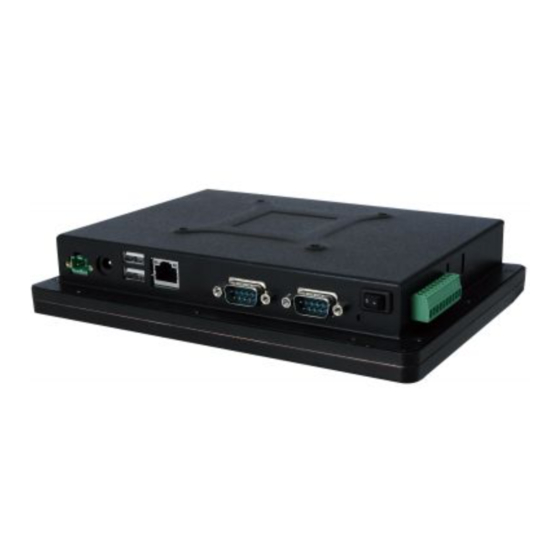
Page 14: Bottom Panel
IOVU-07F-AD RISC-based Panel PC 1.5 Bottom Panel The bottom panel contains the I/O interfaces as shown in Figure 1-4. Figure 1-4: Bottom Panel 1.6 Rear Panel The rear panel has four VESA 75 mounting screw holes. Figure 1-5: Rear Panel... -
Page 15: Left Panel
IOVU-07F-AD RISC-based Panel PC 1.7 Left Panel The left panel has a 1.5 W speaker. Figure 1-6: Left Panel 1.8 Right Panel The right panel has a 10-pin I/O connecter which supports CAN 2.0B and four digital I/O. Figure 1-7: Right Panel... -
Page 16: System Specifications
IOVU-07F-AD RISC-based Panel PC 1.9 System Specifications The IOVU-07F-AD technical specifications are listed in Table 1-2. System Freescale™ i.MX6 Cortex™-A9 quad-core, 1.2 GHz Memory On-board 1 GB DDR3 SDRAM Android 4.2 Boot Flash 4 GB eMMC NAND flash Storage One SD card slot (max. 32 GB) 1 x Speaker (1.5 W) -
Page 17: Table 1-2: Technical Specifications
IOVU-07F-AD RISC-based Panel PC 1 x 2-pin power terminal block (9 V ~ 30 V DC) Power Input 1 x Power jack (9 V ~ 30 V DC) 1 x DB-9 RS-232, full function (COM 1) RS-232/422/485 1 x DB-9 RS-232/422/485, software configurable (COM 2) USB 2.0... -
Page 18: Dimensions
IOVU-07F-AD RISC-based Panel PC 1.10 Dimensions The dimensions are shown below. Figure 1-8: Dimensions (unit: mm) Page 9... -
Page 19: Unpacking
IOVU-07F-AD RISC-based Panel PC Chapter Unpacking Page 10... -
Page 20: Packing List
If any of the components listed in the checklist below are missing, do not proceed with the installation. Contact the IEI reseller or vendor the IOVU-07F-AD was purchased from or contact an IEI sales representative directly by sending an email to ales@ieiworld.com. -
Page 21: Optional Items
IOVU-07F-AD RISC-based Panel PC Quantity Item Image IOVU-07F-AD RISC-based panel PC RS-232 cable (P/N: 32005-001800-100-RS) User manual CD and driver CD Table 2-1: Packing List 2.2 Optional Items The following are optional components which may be separately purchased: Item Image... -
Page 22: Table 2-2: Optional Items
IOVU-07F-AD RISC-based Panel PC Item Image LCD monitor/PPC arm kit, loading capacity of 3kg ~ 7kg (P/N: ARM-11-RS) LCD monitor/PPC stand kit for VESA 75, supporting up to 5kg (P/N: STAND-A08-RS) LCD monitor/PPC stand V type for VESA 75, 0~90 degree adjustable hinge and up to 2.5 kg capacity... -
Page 23: Installation
IOVU-07F-AD RISC-based Panel PC Chapter Installation Page 14... -
Page 24: Anti-Static Precautions
Electrostatic discharge (ESD) can cause serious damage to electronic components, including the IOVU-07F-AD. Dry climates are especially susceptible to ESD. It is therefore critical that whenever the IOVU-07F-AD is accessed internally, or any other electrical component is handled, the following anti-static precautions are strictly adhered to. -
Page 25: Sd Card Installation
IOVU-07F-AD RISC-based Panel PC Anti-static Discharge: If a user open the rear panel of the flat panel PC, to configure the jumpers or plug in added peripheral devices, ground themselves first and wear and anti-static wristband. 3.3 SD Card Installation To install the SD card, follow the instructions below. -
Page 26: Figure 3-2: Hex Nuts On The Bottom Panel
Remove the hex nuts on the bottom panel (Figure 3-2). Step 2: Figure 3-2: Hex Nuts on the Bottom Panel Gently lift the rear cover out of the IOVU-07F-AD. Step 3: Locate the SD card slot (Figure 3-3). Step 4: Insert the SD card into the slot (Figure 3-3). -
Page 27: Mounting The System
Stand mounting The four mounting methods are described below. 3.4.1 Wall Mounting To mount the IOVU-07F-AD onto the wall, please follow the steps below. Select the location on the wall for the wall-mounting bracket. Step 1: Carefully mark the locations of the four screw holes in the bracket on the wall. -
Page 28: Figure 3-4: Wall-Mounting Bracket
Insert the four monitor mounting screws provided in the wall mounting kit into the Step 6: four screw holes on the real panel of the IOVU-07F-AD and tighten until the screw shank is secured against the rear panel (Figure 3-5). -
Page 29: Figure 3-5: Chassis Support Screws
IOVU-07F-AD RISC-based Panel PC Figure 3-5: Chassis Support Screws Secure the panel PC by fastening the retention screw of the wall-mounting Step 9: bracket (Figure 3-6). Page 20... -
Page 30: Panel Mounting
Select the position on the panel to mount the IOVU-07F-AD. Step 1: Cut out a section from the panel that corresponds to the rear panel dimensions Step 2: of the IOVU-07F-AD. Take care that the panel section that is cut out is smaller Page 21... -
Page 31: Arm Mounting
3.4.3 Arm Mounting The IOVU-07F-AD is VESA (Video Electronics Standards Association) compliant and can be mounted on an arm with a 75 mm interface pad. To mount the IOVU-07F-AD on an arm, please follow the steps below. The arm is a separately purchased item. Please correctly mount the arm onto Step 1: the surface it uses as a base. -
Page 32: Figure 3-8: Arm Mounting Retention Screw Holes
Step 3: IOVU-07F-AD, as shown in Figure 3-8. Figure 3-8: Arm Mounting Retention Screw Holes Secure the IOVU-07F-AD to the interface pad by inserting four retention screws Step 4: through the bottom of the mounting arm interface pad and into the IOVU-07F-AD. -
Page 33: Stand Mounting
The IOVU-07F-AD has Video Electronics Standards Association (VESA) standard mounting holes tapped into the rear panel. The monitor stand mounting plate has a matching VESA hole pattern. To mount the IOVU-07F-AD onto a stand, please follow the steps below. Line up the threaded holes on the system rear panel with the screw holes on the Step 1: monitor stand mounting plate. -
Page 34: External I/O Connectors
IOVU-07F-AD RISC-based Panel PC Figure 3-10: Stand Mounting 3.5 External I/O Connectors This section provides an overview of the external I/O connectors of the IOVU-07F-AD. 3.5.1 10-pin I/O Connector The 10-pin I/O connector on the right panel (Figure 1-7) supports the following external peripheral devices: 1 x CAN 2.0B... -
Page 35: Dc Power Input Interfaces
IOVU-07F-AD RISC-based Panel PC Description DIO1 DIO2 DIO3 DIO4 CAN_L CAN_H Table 3-1: I/O Connector Pinouts 3.5.2 DC Power Input Interfaces 3.5.2.1 9 V ~ 30 V DC Power Jack Use the DC power jack to connect the system to a power source. -
Page 36: Ethernet Connector
To connect a LAN cable with an RJ-45 connector, please follow the instructions below. Align the connectors. Align the RJ-45 connector on the LAN cable with the Step 1: RJ-45 connector on the IOVU-07F-AD. See Figure 3-15. Figure 3-15: LAN Connection Page 27... -
Page 37: Figure 3-16: Ethernet Connector
IOVU-07F-AD RISC-based Panel PC Insert the LAN cable RJ-45 connector. Once aligned, gently insert the LAN Step 2: cable RJ-45 connector into the on-board RJ-45 connector. Step 0: The Ethernet connector pinouts are shown below. DESCRIPTION LAN1_MDI[0]+ LAN1_MDI[0]- LAN1_MDI[1]+ LAN1_MDI[1]-... -
Page 38: Serial Interfaces
IOVU-07F-AD RISC-based Panel PC 3.5.4 Serial Interfaces The system has an RS-232 and an RS-232/422/485 serial port connector. 3.5.4.1 RS-232 Serial Interface Pinouts (COM 1) Pinouts for the RS-232 serial port are shown below. Pin Arrangement Description RS232_DCD1 RS232_RXD1 RS232_TXD1... -
Page 39: Connecting The Serial Port
IOVU-07F-AD RISC-based Panel PC The IOVU-07F-AD provides a demo app to select the RS-232, RS-422, or RS-485 mode for the COM 2 port. Please refer to Section 4.8 for details. 3.5.4.3 Connecting the Serial Port Follow the steps below to connect a serial device to the IOVU-07F-AD. -
Page 40: Usb Connectors
IOVU-07F-AD RISC-based Panel PC 3.5.5 USB Connectors The external USB Series "A" receptacle connectors provide easier and quicker access to external USB devices. Follow the steps below to connect USB devices to the IOVU-07F-AD. Locate the USB Series "A" receptacle connectors. The locations of the USB Step 1: Series "A"... -
Page 41: System Maintenance
IOVU-07F-AD RISC-based Panel PC 3.6 System Maintenance If the components of the IOVU-07F-AD fail, they must be replaced. Please contact the system reseller or vendor to purchase the replacement parts. NOTE: A user cannot replace a motherboard. If the motherboard fails it must be shipped back to IEI to be replaced. -
Page 42: Using The Iovu-07F-Ad
IOVU-07F-AD RISC-based Panel PC Chapter Using the IOVU-07F-AD Page 33... -
Page 43: Power-On/Off Procedure
The system is securely mounted if required The power cables are plugged in 4.1.2 Power-on Procedure To power-on the IOVU-07F-AD , just press the power switch to turn on the system. Figure 4-1: Power Switch 4.1.3 Power-off Procedure To power-off the IOVU-07F-AD, please follow the steps below:... -
Page 44: Figure 4-2: Power-Off Menu
IOVU-07F-AD RISC-based Panel PC Press and hold the power switch until the screen in Figure 4-2 appears. Step 1: Tap Power off. Figure 4-2: Power-off Menu A message window prompts as shown in Figure 4-3. Click OK to turn off the Step 2: system. -
Page 45: Home Screen
IOVU-07F-AD RISC-based Panel PC 4.2 Home Screen The IOVU-07F-AD has multiple home screens, allowing users to customize the screen with widgets, apps, folders and shortcuts. The following sections describe the basic technique to manage the home screen. 4.2.1 Switching between Home Screens Swipe left or right to switch between home screens. -
Page 46: Favorites Tray
IOVU-07F-AD RISC-based Panel PC 4.2.2 Favorites Tray The Favorites tray at the side of each home screen allows users to keep the most important or frequently used shortcuts and folders. Long press an item on the home screen. When it vibrates, drag it to the Favorites tray or move it from the Favorites tray. -
Page 47: Adding Shortcut
IOVU-07F-AD RISC-based Panel PC 4.2.3 Adding Shortcut To add app or widget shortcuts on the home screen, follow the steps below. Click the launcher button on the home screen to access the launcher/widget Step 1: page. Figure 4-6: Launcher Button... -
Page 48: Arranging The Home Screen
IOVU-07F-AD RISC-based Panel PC 4.2.4 Arranging the Home Screen The items on the home screen can be moved and deleted. Long press an item on the home screen. When it vibrates, drag it where you want. To trash the item on the desktop, drag it to the “X”... -
Page 49: Navigation Buttons
IOVU-07F-AD RISC-based Panel PC 4.3 Navigation Buttons The three navigation buttons shown in Figure 4-9 can always be found at the bottom of every screen. Figure 4-9: Navigation Buttons Buttons Description Back Tap to return to the previous screen. Home Tap to return to the home screen. -
Page 50: Status Bar
IOVU-07F-AD RISC-based Panel PC 4.4 Status Bar The status bar on the top of the screen (Figure 4-10) displays the pending notifications and status, such as battery level or signal strength. Figure 4-10: Status Bar Swipe down from the right of the status bar to view the setting shortcut. -
Page 51: Figure 4-12: Status Bar - Notification
IOVU-07F-AD RISC-based Panel PC Swipe down from the left of the status bar to view notification details. Figure 4-12: Status Bar – Notification Page 42... -
Page 52: Settings
IOVU-07F-AD RISC-based Panel PC 4.5 Settings The Settings menu allows configuration to the IOVU-07F-AD, such as Wi-Fi, volume, screen brightness, etc. To enter the Settings menu, tap Settings on the launcher page. 4.5.1 WIRELESS & NETWORKS Figure 4-13: Wireless and Networks Settings In the WIRELESS &... -
Page 53: More Settings
IOVU-07F-AD RISC-based Panel PC 4.5.1.1 More Settings Figure 4-14: More Settings Menu After tapping More… in the WIRELESS & NETWORKS field, the user can configure the following network settings. Airplane mode: Turns on or turns off the airplane mode. VPN: Sets up and manages Virtual Private Networks (VPNs). -
Page 54: Sound
IOVU-07F-AD RISC-based Panel PC 4.5.2 Sound Figure 4-15: Sound Menu Use the Sound menu to configure the following items. Volumes: Adjusts the volume of alarms, notifications, music, video, games and other media. Default notification: Sets up the notification ringtone. Touch sounds: Enables or disables playing a sound when making screen selection. -
Page 55: Display
IOVU-07F-AD RISC-based Panel PC 4.5.3 Display Figure 4-16: Display Menu Use the Display menu to configure the following items. Brightness: Adjusts the screen brightness. Wallpaper: Sets up the wallpaper. Sleep: Sets up the time of inactivity after which the screen turns to sleep mode. -
Page 56: Storage
IOVU-07F-AD RISC-based Panel PC 4.5.4 Storage The Storage menu displays the status of the internal storage, the inserted SD card and the connected USB storage devices, and allows users to manage the data stored in them. Figure 4-17: Storage Menu... -
Page 57: Apps
IOVU-07F-AD RISC-based Panel PC 4.5.5 Apps The Apps menu displays the applications installed in the device, and allows users to manage them. Figure 4-18: Apps Menu 4.5.6 Users The Users menu allows the user to configure the owner information. Figure 4-19: Users Menu... -
Page 58: Location Access
IOVU-07F-AD RISC-based Panel PC 4.5.7 Location Access Figure 4-20: Location Access Menu Use the Location access menu to configure the following items. Access to my location: Turns on to let the apps obtain the user’s location information. GPS satellites: This item is available only when the Access to my location item is enabled. -
Page 59: Security
Enables to show the information of the device owner on the lock screen. Encrypt phone: Once this item is enabled, the user will need to type a numeric PIN or password to decrypt the IOVU-07F-AD each time when powering on. Make passwords visible: Enables to show password when typing. -
Page 60: Language & Input
Figure 4-22: Language & Input Menu Use the Language & input menu to configure the following items. Language: Sets up the language for IOVU-07F-AD. Spell checker: Allows the user to enable the spell check function and configure its settings. Personal dictionary: Configures the user dictionary. -
Page 61: Backup & Reset
IOVU-07F-AD RISC-based Panel PC 4.5.10 Backup & Reset Figure 4-23: Backup & Reset Menu Use the Back & reset menu to configure the following items. Factory data reset: Erases all data from the internal storage of the IOVU-07F-AD. Page 52... -
Page 62: Add Account
IOVU-07F-AD RISC-based Panel PC 4.5.11 Add account Tap Add account to start setting up an e-mail or corporate account. Figure 4-24: Add Account Menu 4.5.12 Date & Time Figure 4-25: Date & Time Menu Use the Date & time menu to configure the following items. -
Page 63: Accessibility
IOVU-07F-AD RISC-based Panel PC Automatic date & time: Turns on to use the network-provided time. Set date: Sets up the system date. This item is available only when the Automatic date & time item is disabled. Set time: Sets up the system time. This item is available only when the Automatic date &... -
Page 64: About Tablet
IOVU-07F-AD RISC-based Panel PC Large text: Turns on to use large text. Speak passwords: Turns on or off the speak password fucntion. Accessibility shortcut: Turns on to allow the user to quickly enable the accessibility features. Text-to-speech output: Configures the text-to-speech settings. -
Page 65: File Management
Displays the device build number. 4.6 File Management The IOVU-07F-AD provides a file management tool that allows users to manage files in the internal storage and external storage devices. Tap ES File Explorer on the application page to launch it. -
Page 66: Figure 4-29: Possible Storage Devices
The user can tap the storage folder (Figure 4-28) to view all the possible storage devices listed below. sdcard0: Internal storage of the IOVU-07F-AD sdcard1: SD card connected to the IOVU-07F-AD usb1: USB storage device connected to the USB host connector on the bottom panel. Refer to Figure 1-4 for the connector location. -
Page 67: Camera
IOVU-07F-AD RISC-based Panel PC 4.7 Camera The IOVU-07F-AD equips with a 2-megapixel front camera. Tap Camera on the application page to launch it. Figure 4-30: Camera Application 4.8 Configuring the RS-232/422/485 Serial Port and Digital I/O The IOVU-07F-AD provides a demo app, allowing users to configure the RS-232/422/485 serial port (COM 2) and digital I/O settings. -
Page 68: Figure 4-32: Digital I/O Settings
IOVU-07F-AD RISC-based Panel PC In the DIO menu (Figure 4-32), the user can configure the digital I/O settings. Figure 4-32: Digital I/O Settings Page 59... -
Page 69: Interface Connectors
IOVU-07F-AD RISC-based Panel PC Chapter Interface Connectors Page 60... -
Page 70: Peripheral Interface Connectors
IOVU-07F-AD RISC-based Panel PC 5.1 Peripheral Interface Connectors The motherboard of the IOVU-07F-AD comes with a number of peripheral interface connectors and configuration jumpers. The connector locations are shown in Figure 5-1 and Figure 5-2. The Pin 1 locations of the on-board connectors are also indicated in the diagrams below. -
Page 71: Internal Peripheral Connectors
Internal peripheral connectors are found on the motherboard and are only accessible when the motherboard is outside of the chassis. The table below shows a list of the peripheral interface connectors on the IOVU-07F-AD motherboard. Pinouts of these connectors can be found in the following sections. -
Page 72: Boot Mode Setting Switches (Sw1, Sw2)
IOVU-07F-AD RISC-based Panel PC 5.2.1 Boot Mode Setting Switches (SW1, SW2) PIN NO. DESCRIPTION PIN NO. DESCRIPTION Table 5-2: Boot Mode Setting Switches (SW1, SW2) Pinouts 5.2.2 Camera Connector (CAMERA1) PIN NO. DESCRIPTION PIN NO. DESCRIPTION CSI_MCLK CSI_D8 SDATA1 VDD_CAM2V8... -
Page 73: Downloader Mode Switch (Sw3)
IOVU-07F-AD RISC-based Panel PC 5.2.4 Downloader Mode Switch (SW3) PIN NO. DESCRIPTION CFG1_5 Table 5-5: Downloader Mode Switch (SW3) Pinouts 5.2.5 HP-out Connector (CN3) PIN NO. DESCRIPTION HP_OL EARPHONE_DET HP_OR Table 5-6: HP-out Connector (CN3) Pinouts 5.2.6 JATG Interface for Wi-Fi Module (CN6) PIN NO. -
Page 74: Microphone Connector (Mic1)
IOVU-07F-AD RISC-based Panel PC PIN NO. DESCRIPTION PIN NO. DESCRIPTION LCD_VGL C_TXOUT2+ LCD_UD C_TXOUT2- LCD_LR VLED- C_TXOUT1+ VLED- C_TXOUT1- LCD_SUP C_TXOUT0+ LCD_SELB C_TXOUT0- LCD_DUNI LCD_STBY LCD_RST VLCD_3V3 VLCD_LCD C_TXOUT3+ VLCD_LCD_COM Table 5-8: LCD Connector (LCD1) Pinouts 5.2.8 Microphone Connector (MIC1) PIN NO. -
Page 75: Rfid Connector (Cn11)
IOVU-07F-AD RISC-based Panel PC 5.2.10 RFID Connector (CN11) PIN NO. DESCRIPTION NXP_TX NXP_RX NFC_IRQ SRST S1CLK VMAIN VMAIN Table 5-11: RFID Connector (CN11) Pinouts 5.2.11 SD Card Slot (CN10) PIN NO. DESCRIPTION SDIO3_DATA3 SDIO3_CMD SD_3P3V SDIO3_CLK SDIO3_DATA0 SDIO3_DATA1 SDIO3_DATA2 SDIO3_nCD... -
Page 76: Speaker Connector (Cn4)
IOVU-07F-AD RISC-based Panel PC 5.2.12 Speaker Connector (CN4) PIN NO. DESCRIPTION SPK_N SPK_P Table 5-13: Speaker Connector (CN4) Pinouts 5.2.13 Touchscreen Connector (CN2) PIN NO. DESCRIPTION VCC_CTP TR_nRST- I2C_SCL3 I2C_SDA3 Table 5-14: Touchscreen Connector (CN2) Pinouts Page 67... -
Page 77: A Safety Precautions
IOVU-07F-AD RISC-based Panel PC Appendix Safety Precautions Page 68... -
Page 78: Safety Precautions
Do not apply voltage levels that exceed the specified voltage range. Doing so may cause fire and/or an electrical shock. Electric shocks can occur if the IOVU-07F-AD chassis is opened when the IOVU-07F-AD is running. Do not drop or insert any objects into the ventilation openings of the IOVU-07F-AD. -
Page 79: Anti-Static Precautions
Electrostatic discharge (ESD) can cause serious damage to electronic components, including the IOVU-07F-AD. Dry climates are especially susceptible to ESD. It is therefore critical that whenever the IOVU-07F-AD is opened and any of the electrical components are handled, the following anti-static precautions are strictly adhered to. -
Page 80: Product Disposal
Please follow the national guidelines for electrical and electronic product disposal. A.2 Maintenance and Cleaning Precautions When maintaining or cleaning the IOVU-07F-AD, please follow the guidelines below. A.2.1 Maintenance and Cleaning Prior to cleaning any part or component of the IOVU-07F-AD, please read the details below. Page 71... -
Page 81: Cleaning Tools
In such case, the product will be explicitly mentioned in the cleaning tips. Below is a list of items to use when cleaning the IOVU-07F-AD. C loth – Although paper towels or tissues can be used, a soft, clean piece of cloth is recommended when cleaning the IOVU-07F-AD. -
Page 82: B Hazardous Materials Disclosure
IOVU-07F-AD RISC-based Panel PC Appendix Hazardous Materials Disclosure Page 73... -
Page 83: Hazardous Materials Disclosure Table For Ipb Products Certified As Rohs Compliant Under 2002/95/Ec Without Mercury
IOVU-07F-AD RISC-based Panel PC B.1 Hazardous Materials Disclosure Table for IPB Products Certified as RoHS Compliant Under 2002/95/EC Without Mercury The details provided in this appendix are to ensure that the product is compliant with the Peoples Republic of China (China) RoHS standards. The table below acknowledges the presences of small quantities of certain materials in the product, and is applicable to China RoHS only. - Page 84 IOVU-07F-AD RISC-based Panel PC Part Name Toxic or Hazardous Substances and Elements Lead Mercury Cadmium Hexavalent Polybrominated Polybrominated Biphenyls Diphenyl (Pb) (Hg) (Cd) Chromium (CR(VI)) (PBB) Ethers (PBDE) Housing Display Printed Circuit Board Metal Fasteners Cable Assembly Fan Assembly Power Supply...
- Page 85 IOVU-07F-AD RISC-based Panel PC 此附件旨在确保本产品符合中国 RoHS 标准。以下表格标示此产品中某有毒物质的含量符 合中国 RoHS 标准规定的限量要求。 本产品上会附有”环境友好使用期限”的标签,此期限是估算这些物质”不会有泄漏或突变”的 年限。本产品可能包含有较短的环境友好使用期限的可替换元件,像是电池或灯管,这些元 件将会单独标示出来。 部件名称 有毒有害物质或元素 铅 汞 镉 六价铬 多溴联苯 多溴二苯 醚 (Pb) (Hg) (Cd) (CR(VI)) (PBB) (PBDE) 壳体 显示 印刷电路板 金属螺帽 电缆组装 风扇组装 电力供应组装 电池 O: 表示该有毒有害物质在该部件所有物质材料中的含量均在 SJ/T11363-2006 标准规定的限量要求以下。...
Need help?
Do you have a question about the IOVU-07F-AD and is the answer not in the manual?
Questions and answers