
Related Manuals for IEI Technology IBX-700 Series


Summary of Contents for IEI Technology IBX-700 Series
- Page 1 IBX-700 Integrated Service Computer IBX-700 Series Integrated Service Computer Page i...
- Page 2 IBX-700 Integrated Service Computer Revision Date Version Changes 2008-03 1.01 Modified the ODD replacement procedures 2008-02 1.00 Initial Release Page ii...
- Page 3 IBX-700 Integrated Service Computer Copyright COPYRIGHT NOTICE The information in this document is subject to change without prior notice in order to improve reliability, design and function and does not represent a commitment on the part of the manufacturer. In no event will the manufacturer be liable for direct, indirect, special, incidental, or consequential damages arising out of the use or inability to use the product or documentation, even if advised of the possibility of such damages.
-
Page 4: Manual Conventions
Cautionary messages should also be heeded to help reduce the chance of losing data or damaging the IBX-700 Series. Cautions are easy to recognize. The word “caution” is written as “CAUTION,” both capitalized and bold and is followed. The italicized text is the cautionary message. - Page 5 IBX-700 Integrated Service Computer CAUTION: This is an example of a caution message. Failure to adhere to cautions messages may result in permanent damage to the IBX-700 Series. Please take caution messages seriously. NOTE: These messages inform the reader of essential but non-critical information. These messages should be read carefully as any directions or instructions contained therein can help avoid making mistakes.
-
Page 6: Packing List
IBX-700 Series from or contact an IEI sales representative directly. To contact an IEI sales representative, please send an email to sales@iei.com.tw. The items listed below should all be included in the IBX-700 Series package. 1 x IBX-700 Series Integrated Service Computer... -
Page 7: Table Of Contents
IBX-700 Integrated Service Computer Table of Contents INTRODUCTION..................... 1 1.1 IBX-700 S ..................2 ERIES VERVIEW 1.1.1 IBX-700 Series Benefits ..................2 1.1.2 IBX-700 Series Features ..................3 1.2 IBX-700 S ................ 3 ERIES ODEL ARIATIONS 1.3 T ..................6... - Page 8 IBX-700 Integrated Service Computer 3.1.3.4 ICH6-M Southbridge Chipset ..............23 3.1.4 Intel® 915GM Integrated Graphics Media Accelerator 900 ......24 3.1.5 Ethernet Controller Specifications..............25 3.1.5.1 Overview....................25 3.1.5.2 PCI Express GbE Features................ 25 3.2 P ..............26 ERIPHERAL NTERFACE ONNECTORS 3.2.1 Peripheral Interface Connectors ..............
- Page 9 IBX-700 Integrated Service Computer 5.3 A ....................... 45 DVANCED 5.3.1 CPU Configuration..................46 5.3.2 IDE Configuration ................... 47 5.3.2.1 IDE Master, IDE Slave ................49 5.3.3 Super IO Configuration..................54 5.3.4 Hardware Health Configuration..............59 5.3.5 Remote Access Configuration ................61 5.3.6 USB Configuration...................
- Page 10 IBX-700 Integrated Service Computer 7.3.1 Refresh Time Setting..................109 7.3.2 High Limit Value and Low Limit Value Setting ..........109 7.4 F ........................110 7.4.1 Refresh Time Setting..................111 7.4.2 High Limit Value and Low Limit Value Setting ..........111 7.4.3 Smart Fan Setting ...................112 7.4.3.1 On/Off Mode....................112 7.4.3.2 PWM Mode....................112 7.4.3.3 Automatic Mode..................113...
- Page 11 IBX-700 Integrated Service Computer 8.4.3.1 Power Module Removal ................. 132 8.4.3.2 Power Module Installation..............134 8.4.4 DIMM Replacement ..................134 8.4.5 ODD Replacement (Optional) ............... 135 8.4.5.1 ODD Removal ..................135 8.4.5.2 ODD Installation..................137 8.4.6 Riser Card Replacement (Optional) .............. 137 SAFETY PRECAUTIONS...................
- Page 12 IBX-700 Integrated Service Computer G.2 F ..................169 EATURES AND ENEFITS G.3 A RAID U ............. 169 CCESSING THE ICRON TILITY G.4 C RAID A ..................172 REATING A RRAY G.5 D RAID A ..................179 ELETING A RRAY G.6 R -RAID ..............
- Page 13 IBX-700 Integrated Service Computer List of Figures Figure 1-1: IBX-700 Series Integrated Service Computer .........2 Figure 1-2: Power Adapter ...................9 Figure 2-1: IBX-700 Series Dimensions (mm) ............15 Figure 2-2: IBX-700 Series Front Panel ..............16 Figure 2-3: IBX-700 Series Rear Panel ..............16 Figure 2-4: Internal Overview..................18...
- Page 14 IBX-700 Integrated Service Computer Figure 6-14: Intel® Graphics Media Accelerator Driver Installing Notice....93 Figure 6-15: Intel® Graphics Media Accelerator Installation Complete ....94 Figure 6-16: Windows Control Panel.................95 Figure 6-17: System Icon....................95 Figure 6-18: Device Manager Tab ................96 Figure 6-19: Device Manager List ................96 Figure 6-20: Search for Suitable Driver..............97 Figure 6-21: Locate Driver Files.................97 Figure 6-22: Location Browsing Window..............98...
- Page 15 IBX-700 Integrated Service Computer Figure 7-15: Temperature Page – High Limit and Low Limit ....... 116 Figure 7-16: Cash Drawer Page ................117 Figure 7-17: WDT Page .................... 118 Figure 7-18: DIO Page ....................119 Figure 7-19: Load/Save Page .................. 120 Figure 8-1: Cover Case Thumb Screws ..............
- Page 16 Table 1-1: Model Variations..................5 Table 1-2: CF Card with Preinstalled OS ..............5 Table 1-3: Technical Specifications ................7 Table 1-4: IBX-700 Series Power Module Options .............7 Table 1-5: DC-to-DC Power Module Specifications ...........8 Table 1-6: Power Adapter Specifications..............10 Table 1-7: Wireless Module Specifications ..............11 Table 3-1: Chipset Variations..................22...
- Page 17 IBX-700 Integrated Service Computer List of BIOS Menus Menu 1: Main ....................44 Menu 2: Advanced.......................46 Menu 3: CPU Configuration ..................47 Menu 4: IDE Configuration ..................48 Menu 5: IDE Master and IDE Slave Configuration ...........50 Menu 6: Super IO Configuration ................54 Menu 7: Hardware Health Configuration ..............59 Menu 8: Remote Access Configuration [Advanced] ..........61 Menu 9: USB Configuration ..................64...
- Page 18 IBX-700 Integrated Service Computer THIS PAGE IS INTENTIONALLY LEFT BLANK Page xviii...
-
Page 19: Introduction
IBX-700 Integrated Service Computer Chapter Introduction Page 1... -
Page 20: Series Overview
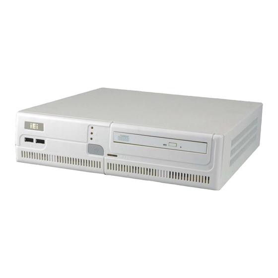
1.1 IBX-700 Series Overview Figure 1-1: IBX-700 Series Integrated Service Computer The IBX-700 Series is an Intel® Celeron® M based integrated service solution that can be applied in diverse operational environments and implemented in multi-faceted point-of-sale (POS) applications. The IBX-700 Series comes fully kitted with a high-performance motherboard and a host of other peripheral interface connectors. -
Page 21: Series Features
Optional 802.11b/g wireless LAN module Support 9 V ~ 36 V power (optional) 1.2 IBX-700 Series Model Variations The IBX-700 Series has one preinstalled 1 GB DDR2 memory module with different type CPU. The model information is listed in Table 1-1 below. IBX-700D-9103-R10... - Page 22 IBX-700 Integrated Service Computer IBX-700D-9153-R10 Wireless Expansion Power -WSOOC/CM370/1GB/80G 1.5 GHz Intel® Celeron® M 12 V with 1 MB L2 cache (PGA) -WSIGC/CM370/1GB/80G 1.5 GHz Intel® Celeron® M 12 V with 1 MB L2 cache (PGA) -WSEGC/CM370/1GB/80G 1.5 GHz Intel® Celeron® M PCIe x1 12 V with 1 MB L2 cache (PGA)
-
Page 23: Table 1-1: Model Variations
1 MB L2 cache (PGA) Table 1-1: Model Variations Optional 1 GB CF card pre-installed with Windows® WEPOS or Windows® XP Embedded is also provided by IEI for the IBX-700 Series. The information of the optional CF card is listed below. Model... -
Page 24: Technical Specifications
IBX-700 Integrated Service Computer 1.3 Technical Specifications The specifications for the Intel® based IBX-700 are listed below. IBX-700-9103 IBX-700-9153 1 GHz ULV Intel® Celeron M 1.5 GHz Intel® Celeron M 512 KB L2 Cache (BGA type) 1 MB L2 Cache (PGA type) Northbridge: Intel®... -
Page 25: Power Module Specifications
1.4 Power Module Specifications 1.4.1 Power Module Options The IBX-700 Series supports either a 12 V DC input or a 9 V ~ 36 V DC input. The input support depends on the power module installed in the system. The two power modules... -
Page 26: Table 1-5: Dc-To-Dc Power Module Specifications
IBX-700 Integrated Service Computer Model Name: IDD-12490A IDD-9364120A 12 V DC 9 V DC~36 V DC Input Output: 10 A (pass thru.) 4 A (Max.) 12 V 10 A (Max.) 10 A (Max.) 8 A (Max.) 8 A (Max.) 3.3 V 0.3 A (Max.) 0.3 A (Max.) -12 V... -
Page 27: Power Adapter
IBX-700 Integrated Service Computer 1.5 Power Adapter The IBX-700 Series models are shipped with an 84 W power adapter. Figure 1-2: Power Adapter The specifications for the adapter are listed in Table 1-6: 12.0 V Nominal 11.2 V – 12.6 V... -
Page 28: Table 1-6: Power Adapter Specifications
IBX-700 Integrated Service Computer 115 V ~ 230 V Nominal 264 V Max. 47 Hz ~ 63 Hz Frequency 1.5 A (rms Max.)@100 V AC Steady AC Current 80% (typical) Efficiency Operating 6.0 A: 0ºC ~ 40ºC 7.0 A: 0ºC ~ 25ºC Temperature Storage -30ºC ~ 60ºC... -
Page 29: Wireless Lan Module (Optional)
IBX-700 Integrated Service Computer 1.6 Wireless LAN Module (Optional) An Azurewave AW-GE780 wireless 802.11b/g PCIe mini card is installed on the optional PCI/PCIe riser card. The specifications for the wireless LAN module are listed in Table 1-7: AW-GE780 IEEE 802.11 b/g Standard PCIe mini card Interface... - Page 30 IBX-700 Integrated Service Computer THIS PAGE IS INTENTIONALLY LEFT BLANK Page 12...
-
Page 31: Mechanical Description
IBX-700 Integrated Service Computer Chapter Mechanical Description Page 13... -
Page 32: Series Mechanical Overview
A CompactFlash® slot on the rear panel supports one Type I or Type II CF card. 2.2 IBX-700 Series Physical Dimensions The dimensions of the IBX-700 Series are listed below and shown in Figure 2-1. Height: 75.00 mm Width: 300.00 mm Length: 309.00 mm... -
Page 33: External Overview
2.3 External Overview 2.3.1 Front Panel The front panel of the IBX-700 Series has two USB 2.0 ports, indicators and power button. The optional DVD combo drive is also accessed from the front panel. An overview of the rear panel is shown in Figure 2-3 below. -
Page 34: Rear Panel Overview
Figure 2-2: IBX-700 Series Front Panel 2.3.2 Rear Panel Overview The IBX-700 Series contains the external I/O interface connectors, power connectors, serial port LEDs and a CF slot. An overview of the rear panel is shown in Figure 2-3 below. -
Page 35: Rear Panel Connectors And Indicators
IBX-700 Integrated Service Computer 2.3.2.1 Rear Panel Connectors and Indicators The connectors, indicators and switches listed in this section are shown in Figure 2-3 above. The rear panel I/O connectors are listed below: 1 x 12 V DC inlet 4 x RS-232 serial port connectors (COM1, COM2, COM3 and COM4 with selectable voltage) 2 x RS-232 serial port connectors (COM5 and COM6) 1 x RJ-45 GbE connector... -
Page 36: Internal Overview
IBX-700 Integrated Service Computer 2.4 Internal Overview The IBX-700 Series preinstalled internal components are listed below: 1 x IEI POS-9103/POS-9153 motherboard 1 x IEI IDD-12490A/IDD-9364120A power module 1 x 1 GB DDR2 DIMM module 1 x 80 GB 2.5” SATA HDD 1 x 2.5”... -
Page 37: System Components
IBX-700 Integrated Service Computer Chapter System Components Page 19... -
Page 38: Series Motherboard
Appendix B. 3.1 IBX-700 Series Motherboard The IBX-700 Series all has a POS-9103 or POS-9153 motherboard installed in the system. The difference between these two motherboard is the preinstalled CPU. (See Table 1-1) The following sections describe the relevant connectors and jumpers on the motherboard. -
Page 39: Cpu Support
CPU on-board. If the CPU fails, the motherboard has to be replaced. Please contact the IEI reseller or vendor you purchased the IBX-700-9103 from or contact an IEI sales representative directly. To contact an IEI sales representative, please send an email to sales@iei.com.tw. -
Page 40: Intel Celeron M Specifications
IBX-700 Integrated Service Computer ® ® 3.1.2.1 Intel Celeron M Specifications The specifications for the Intel® Celeron® M processor are listed below Features a new microarchitecture designed from the ground up: Hardware control for improved stack management Micro-ops fusion for instruction execution Advanced branch prediction capability Level 2 Advanced Transfer Cache (ATC) delivers a high data throughput channel between the Level 2 cache and processor core... -
Page 41: Intel 910Gmle Northbridge Chipset
IBX-700 Integrated Service Computer ® 3.1.3.2 Intel 910GMLE Northbridge Chipset The Intel® 910GMLE Northbridge chipset comes with the following features: 400 MHz Front Side Bus Supports dual-channel non-ECC DDR2 400 MHz memory technology Intel® Stable Image Technology Supports a unified graphics driver. Enables hardware changes without impact to IT software image stability. -
Page 42: Intel® 915Gm Integrated Graphics Media Accelerator 900
IBX-700 Integrated Service Computer Enhanced DMA controller Interrupt controller Timer functions Integrated SATA host controller with DMA operations interfaced to two SATA connectors on the POS-9153 Integrated IDE controller supports Ultra ATA 100/66/33 Supports the four USB 2.0 devices on the POS-9153 with four UHCI controllers and one EHCI controller Complies with System Management Bus (SMBus) Specification, Version 2.0 Supports Audio Codec ’97 (AC’97) Revision 2.3... -
Page 43: Ethernet Controller Specifications
IBX-700 Integrated Service Computer Slope Scale Depth Bias Two-Sided Stencil Microsoft DirectX* 9 Vertex Shader 2.0 and Transform and Lighting supported in software through highly optimized Processor Specific Geometry Pipeline (PSGP) DirectX Texture Decompression OpenGL* 1.4 support Advanced Display Technology 400 MHz DAC frequency for up to 2048x1526 resolution for both analog and digital displays Two Serial Digital Video Out (SDVO) ports for flat-panel monitors and/or... -
Page 44: Peripheral Interface Connectors
3.2 Peripheral Interface Connectors Section 3.2.1 lists all the peripheral interface connectors seen in Section 3.1.1. 3.2.1 Peripheral Interface Connectors Table 3-2 shows a list of the peripheral interface connectors on the POS motherboard used for the IBX-700 Series. Connector Type Label... -
Page 45: External Interface Panel Connectors
IBX-700 Integrated Service Computer USB connector 8-pin header USB2 Table 3-2: Peripheral Interface Connectors 3.2.2 External Interface Panel Connectors Table 3-3 lists the rear panel connectors on the POS motherboard. Connector Type Label Audio jacks (line-out, mic-in) Audio jack AUDIO1 Cash drawer connector (1) RJ-12 connector Cash drawer connector (2) -
Page 46: On-Board Jumpers
IBX-700 Integrated Service Computer 3.3 On-board Jumpers NOTE: A jumper is a metal bridge used to close an electrical circuit. It consists of two or three metal pins and a small metal clip (often protected by a plastic cover) that slides over the pins to connect them. -
Page 47: Fsb Select Jumper Settings
IBX-700 Integrated Service Computer See Table 3-5 Jumper Settings: See Figure 3-3 Jumper Location: The ATX Power Select jumper specifies the systems power mode as AT or ATX. ATX Power Select jumper settings are shown in Table 3-5. ATX Power Select Description Short 1-2 Use ATX power... -
Page 48: Clear Cmos Jumper
IBX-700 Integrated Service Computer See Table 3-6 Jumper Settings: See Figure 3-4 Jumper Location: The FSB Select jumper specifies the front side bus (FSB) as 400 MHz or 533 MHz. FSB Select jumper settings are shown in Table 3-5. FSB Select Description Short 1-2 400 MHz... -
Page 49: Table 3-7: Clear Cmos Jumper Settings
IBX-700 Integrated Service Computer If the IBX-700 Series fails to boot due to improper BIOS settings, the clear CMOS jumper clears the CMOS data and resets the system BIOS information. To do this, use the jumper cap to close pins 2 and 3 for a few seconds then reinstall the jumper clip back to pins 1 and 2. -
Page 50: Com 1/2 Pin 9 Setting Jumper
IBX-700 Integrated Service Computer Figure 3-5: Clear CMOS Jumper 3.3.4 COM 1/2 Pin 9 Setting Jumper Jumper Label: J_COM1 6-pin header Jumper Type: See Table 3-8 Jumper Settings: See Figure 3-6 Jumper Location: The COM 1/2 Pin 9 Setting jumper configures pin 9 on COM 1 and COM 2 as either a +5 V, or +12 V power source. -
Page 51: Com 3/4 Pin 9 Setting Jumper
IBX-700 Integrated Service Computer The COM 1/2 Pin 9 Setting jumper location is shown in Figure 3-6 below. Figure 3-6: COM 1/2 Pin 9 Setting Jumper Location 3.3.5 COM 3/4 Pin 9 Setting Jumper Jumper Label: J_COM2 6-pin header Jumper Type: See Table 3-9 Jumper Settings: See Figure 3-7... -
Page 52: Figure 3-7: Com 3/4 Pin 9 Setting Jumper Location
IBX-700 Integrated Service Computer COM 3/4 Voltage Description Short 1 – 3 COM 3 Pin 9 use +5 V Default Short 3 – 5 COM 3 Pin 9 use +12 V Short 2 – 4 COM 4 Pin 9 use +5 V Default Short 4 –... -
Page 53: Installation
IBX-700 Integrated Service Computer Chapter Installation Page 35... -
Page 54: Anti-Static Precautions
Electrostatic discharge (ESD) can cause serious damage to electronic components, including the POS motherboard and the power module. (Dry climates are especially susceptible to ESD.) It is therefore critical that whenever the IBX-700 Series is opened and any electrical component handled, the following anti-static precautions are strictly adhered to. -
Page 55: Unpacking
IBX-700 Integrated Service Computer 4.2.2 Unpacking After the IBX-700 Series is received make sure the following components are included in the package. If any of these components are missing, please contact the IBX-700 Series reseller or vendor where it was purchased or contact an IEI sales representative immediately. -
Page 56: Compactflash® Card Installation
Table 4-1: Package List Contents 4.2.3 CompactFlash® Card Installation The IBX-700 Series has one CF slot on the rear panel. To install the CF card, follow the instructions below. Locate the CF card slot plastic cover on the rear panel. -
Page 57: Foot Pad Installation
Replace the CF card slot cover. Step 4: Step 0: 4.2.4 Foot Pad Installation The IBX-700 Series is shipped with four foot pads. To install the foot pads, follow the instructions below. Turn the IBX-700 over. Step 1: Carefully mark the locations of the four foot pads on the bottom surface. -
Page 58: Power-On Procedure
The power cables are plugged in The system is securely mounted 4.3.2 Power-on Procedure To power-on the IBX-700 Series please follow the steps below: Push the power button on the front panel. Step 1: Once turned on, the blue power LED should be turned on. See Figure 4-2. -
Page 59: Ami Bios
IBX-700 Integrated Service Computer Chapter AMI BIOS Page 41... -
Page 60: Introduction
IBX-700 Integrated Service Computer 5.1 Introduction A licensed copy of AMI BIOS is preprogrammed into the ROM BIOS. The BIOS setup program allows users to modify the basic system configuration. This chapter describes how to access the BIOS setup program and the configuration options that may be changed. -
Page 61: Getting Help
IBX-700 Integrated Service Computer F1 key General help, only for Status Page Setup Menu and Option Page Setup Menu F2 /F3 key Change color from total 16 colors. F2 to select color forward. F10 key Save all the CMOS changes, only for Main Menu Table 5-1: BIOS Navigation Keys 5.1.3 Getting Help When F1 is pressed a small help window describing the appropriate keys to use and the... -
Page 62: Main
IBX-700 Integrated Service Computer 5.2 Main The Main BIOS menu (BIOS Menu 1) appears when the BIOS Setup program is entered. The Main menu gives an overview of the basic system information. BIOS Menu 1: Main System Overview The System Overview lists a brief summary of different system components. The fields in System Overview cannot be changed. -
Page 63: Advanced
IBX-700 Integrated Service Computer Count: The number of CPUs on the motherboard System Memory: Displays the auto-detected system memory. Lists memory size Size: The System Overview field also has two user configurable fields: System Time [xx:xx:xx] Use the System Time option to set the system time. Manually enter the hours, minutes and seconds. -
Page 64: Cpu Configuration
IBX-700 Integrated Service Computer BIOS Menu 2: Advanced 5.3.1 CPU Configuration Use the CPU Configuration menu (BIOS Menu 3) to view detailed CPU specifications and configure the CPU. Page 46... -
Page 65: Ide Configuration
IBX-700 Integrated Service Computer BIOS Menu 3: CPU Configuration The CPU Configuration menu (BIOS Menu 3) lists the following CPU details: Manufacturer: Lists the name of the CPU manufacturer Brand String: Lists the brand name of the CPU being used Frequency: Lists the CPU processing speed FSB Speed: Lists the FSB speed Cache L1: Lists the CPU L1 cache size... -
Page 66: Ata/Ide Configurations [Enhanced]
IBX-700 Integrated Service Computer BIOS Menu 4: IDE Configuration ATA/IDE Configurations [Enhanced] Use the ATA/IDE Configurations option to configure the ATA/IDE controller. Disables the on-board ATA/IDE controller. Disabled Configures the on-board ATA/IDE controller to be in Compatible compatible mode. In this mode, a SATA channel will replace one of the IDE channels. -
Page 67: Ide Master, Ide Slave
IBX-700 Integrated Service Computer IDE Master and IDE Slave When entering setup, BIOS auto detects the presence of IDE devices. BIOS displays the status of the auto detected IDE devices. The following IDE devices are detected and are shown in the IDE Configuration menu: Primary IDE Master Primary IDE Slave Secondary IDE Master... -
Page 68: Auto-Detected Drive Parameters
IBX-700 Integrated Service Computer BIOS Menu 5: IDE Master and IDE Slave Configuration Auto-Detected Drive Parameters The “grayed-out” items in the left frame are IDE disk drive parameters automatically detected from the firmware of the selected IDE disk drive. The drive parameters are listed as follows: Device: Lists the device type (e.g. -
Page 69: Type [Auto]
IBX-700 Integrated Service Computer Async DMA: Indicates the highest Asynchronous DMA Mode that is supported. Ultra DMA: Indicates the highest Synchronous DMA Mode that is supported. S.M.A.R.T.: Indicates whether or not the Self-Monitoring Analysis and Reporting Technology protocol is supported. Type [Auto] Use the Type BIOS option select the type of device the AMIBIOS attempts to boot from after the Power-On Self-Test (POST) is complete. -
Page 70: Block (Multi Sector Transfer) [Auto]
IBX-700 Integrated Service Computer BIOS is prevented from using the LBA mode control on Disabled the specified channel. BIOS auto detects the LBA mode control on the specified Auto EFAULT channel. Block (Multi Sector Transfer) [Auto] Use the Block (Multi Sector Transfer) to disable or enable BIOS to auto detect if the device supports multi-sector transfers. -
Page 71: Dma Mode [Auto]
IBX-700 Integrated Service Computer PIO mode 4 selected with a maximum transfer rate of 16.6MBps (This setting generally works with all hard disk drives manufactured after 1999. For other disk drives, such as IDE CD-ROM drives, check the specifications of the drive.) DMA Mode [Auto] Use the DMA Mode BIOS selection to adjust the DMA mode options. -
Page 72: Super Io Configuration
IBX-700 Integrated Service Computer 5.3.3 Super IO Configuration Use the Super IO Configuration menu (BIOS Menu 6) to set or change the configurations for the FDD controllers, parallel ports and serial ports. BIOS Menu 6: Super IO Configuration Serial Port1 Address [3F8/IRQ4] Use the Serial Port1 Address option to select the Serial Port 1 base address. -
Page 73: Serial Port1 Mode [Normal]
IBX-700 Integrated Service Computer Serial Port 1 I/O port address is 2E8 and the interrupt 2E8/IRQ3 address is IRQ3 Serial Port1 Mode [Normal] Use the Serial Port1 Mode option to select the transmitting and receiving mode for the first serial port. Serial Port 1 mode is normal Normal EFAULT... -
Page 74: Parallel Port Address [378]
IBX-700 Integrated Service Computer Parallel Port Address [378] Use the Parallel Port Address option to select the parallel port base address. No base address is assigned to the Parallel Port Disabled Parallel Port I/O port address is 378 EFAULT Parallel Port I/O port address is 278 Parallel Port I/O port address is 3BC Parallel Port Mode [Normal] Use the Parallel Port Mode option to select the mode the parallel port operates in. -
Page 75: Parallel Port Irq [Irq7]
IBX-700 Integrated Service Computer system and the parallel port device and the transmission rates between the two are much faster than the Normal mode The parallel port is also be compatible with EPP devices described above Parallel Port IRQ [IRQ7] Use the Parallel Port IRQ selection to set the parallel port interrupt address. -
Page 76: Serial Port4 Irq [10]
IBX-700 Integrated Service Computer Serial port 4 I/O port address is 2E8 EFAULT Serial Port4 IRQ [10] Use the Serial Port4 IRQ option to select the interrupt address for serial port 4. Serial port 4 IRQ address is 10 EFAULT Serial Port5 Address [2F0] Use the Serial Port5 IRQ option to select the interrupt address for serial port 5. -
Page 77: Hardware Health Configuration
IBX-700 Integrated Service Computer Serial port 6I/O port address is 2E0 EFAULT Serial Port6 IRQ [10] Use the Serial Port6 IRQ option to select the interrupt address for serial port 6. Serial port 6 IRQ address is 10 EFAULT 5.3.4 Hardware Health Configuration The Hardware Health Configuration menu (BIOS Menu 7) shows the operating temperature, fan speeds and system voltages. - Page 78 IBX-700 Integrated Service Computer Fan is on all the time Full On Mode EFAULT Fan is off when the temperature is low Automatic mode enough. Parameters must be set by the user. Pulse width modulation set manually PWM Manual mode When the FAN Mode Setting option is in the Automatic Mode, the following parameters can be set.
-
Page 79: Remote Access Configuration
IBX-700 Integrated Service Computer +12Vin 5VSB VBAT 5.3.5 Remote Access Configuration Use the Remote Access Configuration menu (BIOS Menu 8) to configure remote access parameters. The Remote Access Configuration is an AMIBIOS feature and allows a remote host running a terminal program to display and configure the BIOS settings. -
Page 80: Serial Port Number
IBX-700 Integrated Service Computer Remote access configuration options shown below Enabled appear: Serial Port Number Serial Port Mode Redirection after BIOS POST Terminal Type These configuration options are discussed below. Serial Port Number [COM1] Use the Serial Port Number option allows to select the serial port used for remote access. -
Page 81: Usb Configuration
IBX-700 Integrated Service Computer 19200 8,n,1 09600 8,n,1 NOTE: Identical baud rate setting musts be set on the host (a management computer running a terminal software) and the slave Redirection After BIOS POST [Always] Use the Redirection After BIOS POST option to specify when console redirection should occur. -
Page 82: Usb Configuration
IBX-700 Integrated Service Computer BIOS Menu 9: USB Configuration USB Configuration The USB Configuration field shows the system USB configuration. The items listed are: Module Version: x.xxxxx.xxxxx USB Devices Enabled The USB Devices Enabled field lists the USB devices that are enabled on the system USB Function [Enabled] Use the USB Function BIOS option to enable or disable USB function support. -
Page 83: Usb Mass Storage Device Configuration
IBX-700 Integrated Service Computer USB 2.0 Controller [Enabled] Use the USB 2.0 Controller BIOS option to enable or disable the USB 2.0 controller USB 2.0 controller enabled Enabled EFAULT USB 2.0 controller disabled Disabled Legacy USB Support [Enabled] Use the Legacy USB Support BIOS option to enable USB mouse and USB keyboard support. -
Page 84: Usb Mass Storage Reset Delay [20 Sec]
IBX-700 Integrated Service Computer BIOS Menu 10: USB Mass Storage Device Configuration USB Mass Storage Reset Delay [20 Sec] Use the USB Mass Storage Reset Delay option to set the number of seconds POST waits for the USB mass storage device after the start unit command. POST waits 10 seconds for the USB mass storage 10 Sec device after the start unit command. -
Page 85: Device
IBX-700 Integrated Service Computer Device ## The Device## field lists the USB devices that are connected to the system. Emulation Type [Auto] Use the Emulation Type BIOS option to specify the type of emulation BIOS has to provide for the USB device. NOTE: Please note that the device’s formatted type and the emulation type provided by the BIOS must match for a device to boot properly. -
Page 86: Pci/Pnp
IBX-700 Integrated Service Computer Assumes the CD-ROM is formatted as bootable CDROM media. All the devices that support block sizes greater than 512 bytes can only be booted using this option. 5.4 PCI/PnP Use the PCI/PnP menu (BIOS Menu 11) to configure advanced PCI and PnP settings. WARNING! Setting wrong values for the BIOS selections in the PCIPnP BIOS menu may cause the system to malfunction. -
Page 87: Irq# [Available]
IBX-700 Integrated Service Computer IRQ# [Available] Use the IRQ# address to specify what IRQs can be assigned to a particular peripheral device. The specified IRQ is available to be used by Available EFAULT PCI/PnP devices The specified IRQ is reserved for use by Legacy ISA Reserved devices Available IRQ addresses are:... -
Page 88: Boot
IBX-700 Integrated Service Computer DM Channel 1 DM Channel 3 DM Channel 5 DM Channel 6 DM Channel 7 Reserved Memory Size [Disabled] Use the Reserved Memory Size BIOS option to specify the amount of memory that should be reserved for legacy ISA devices. No memory block reserved for legacy ISA devices Disabled EFAULT... -
Page 89: Boot Settings Configuration
IBX-700 Integrated Service Computer BIOS Menu 12: Boot 5.5.1 Boot Settings Configuration Use the Boot Settings Configuration menu (BIOS Menu 13) to configure advanced system boot options. Page 71... -
Page 90: Quick Boot [Enabled]
IBX-700 Integrated Service Computer BIOS Menu 13: Boot Settings Configuration Quick Boot [Enabled] Use the Quick Boot BIOS option to make the computer speed up the boot process. No POST procedures are skipped Disabled Some POST procedures are skipped to decrease Enabled EFAULT the system boot time... -
Page 91: Addon Rom Display Mode [Keep Current]
IBX-700 Integrated Service Computer AddOn ROM Display Mode [Keep Current] Use the AddOn ROM Display Mode option to allow add-on ROM (read-only memory) messages to be displayed. The system forces third party BIOS to display Force BIOS during system boot. The system displays normal information during Keep Current EFAULT... -
Page 92: Boot Device Priority
IBX-700 Integrated Service Computer Can be booted from a remote system through the Enabled EFAULT 5.5.2 Boot Device Priority Use the Boot Device Priority menu to specify the boot sequence from the available devices. Possible boot devices may include: FLOPPY DRIVE CD/DVD 5.5.3 Hard Disk Drives Use the Hard Disk Drives menu to specify the boot sequence of the available HDDs. -
Page 93: Change Supervisor Password
IBX-700 Integrated Service Computer BIOS Menu 14: Security Change Supervisor Password Use the Change Supervisor Password to set or change a supervisor password. The default for this option is Not Installed. If a supervisor password must be installed, select this field and enter the password. After the password has been added, Install appears next to Change Supervisor Password. -
Page 94: Chipset
IBX-700 Integrated Service Computer Clear User Password Use the Clear User Password to clear a user’s password. The default for this option is Not Installed. If a user password must be cleared, use this option. 5.7 Chipset Use the Chipset menu (BIOS Menu 15) to access the Northbridge and Southbridge configuration menus WARNING! Setting the wrong values for the Chipset BIOS selections in the Chipset... -
Page 95: Northbridge Configuration
IBX-700 Integrated Service Computer 5.7.1 NorthBridge Configuration Use the Northbridge Chipset Configuration menu (BIOS Menu 16) to configure the Northbridge chipset. BIOS Menu 16:Northbridge Chipset Configuration Memory Hole [Disabled] Use the Memory Hole option to reserve memory space between 15MB and 16MB for ISA expansion cards that require a specified area of memory to work properly. -
Page 96: Southbridge Configuration
IBX-700 Integrated Service Computer Boots Graphics Adapter Priority [PEG/PCI] Use the Boots Graphics Adapter Priority option to select the graphics controller used as the primary boot device. Select either an integrated graphics controller (IGD) or a combination of PCI graphics controller, a PCI express (PEG) controller or an IGD. Configuration options are listed below: PEG/IGD EFAULT... -
Page 97: Spectrum [Disabled]
IBX-700 Integrated Service Computer BIOS Menu 17:Southbridge Chipset Configuration Spectrum [Disabled] Use the Spectrum option to reduce the EMI. Excess EMI is generated when the system clock generator pulses have extreme values. Spreading the pulse spectrum modulates changes in the extreme values from spikes to flat curves, thus reducing the EMI. This benefit may in some cases be outweighed by problems with timing-critical devices, such as a clock-sensitive SCSI device. -
Page 98: Power
IBX-700 Integrated Service Computer The Azalia (HD Audio) is enabled Azalia The onboard AC’97 automatically detected and enabled AC’97 Audio EFAULT The onboard audio controller is disabled Disabled Cash drawer control [Enabled] Use the Cash drawer control option to enable or disable the control of cash drawer connected to the RJ-12 connectors. -
Page 99: Power Button Mode [On/Off]
IBX-700 Integrated Service Computer Power Button Mode [On/Off] Use the Power Button Mode BIOS to specify how the power button functions. When the power button is pressed the system is either On/Off EFAULT turned on or off When the power button is pressed the system goes into Suspend suspend mode Restore on AC Power Loss [Last State]... -
Page 100: Rtc Resume [Disabled]
IBX-700 Integrated Service Computer Wake event not generated by PCI PME controller Disabled EFAULT activity Wake event generated by PCI PME controller activity Enabled RTC Resume [Disabled] Use the RTC Resume option to specify the time the system should be roused from a suspended state. -
Page 101: Exit
IBX-700 Integrated Service Computer 5.9 Exit Use the Exit menu (BIOS Menu 19) to load default BIOS values, optimal failsafe values and to save configuration changes. BIOS Menu 19:Exit Save Changes and Exit Use the Save Changes and Exit option to save the changes made to the BIOS options and to exit the BIOS configuration setup program. -
Page 102: Discard Changes
IBX-700 Integrated Service Computer Discard Changes Use the Discard Changes option to discard the changes and remain in the BIOS configuration setup program. Load Optimal Defaults Use the Load Optimal Defaults option to load the optimal default values for each of the parameters on the Setup menus. -
Page 103: Driver Installation
IBX-700 Integrated Service Computer Chapter Driver Installation Page 85... -
Page 104: Available Software Drivers
NOTE: The content of the CD may vary throughout the life cycle of the product and is subject to change without prior notice. Visit the IEI website or contact technical support for the latest updates. The following drivers can be installed on the system: Audio driver (Realtek AC’97 Audio Driver) -
Page 105: Realtek Ac`97 Audio Driver Installation
IBX-700 Integrated Service Computer Select the driver to install from the list in Figure 6-1. Detailed driver installation Step 3: instructions follow below. Step 0: 6.3 Realtek AC`97 Audio Driver Installation To install the Realtek AC’97 Audio driver, please follow the steps below. 6.3.1 BIOS Setup Enter the BIOS setup. -
Page 106: Figure 6-3: Preparing Setup Screen
IBX-700 Integrated Service Computer The InstallShield Wizard is prepared to guide the user through the rest of the Step 3: process (Figure 6-3). Figure 6-3: Preparing Setup Screen Once initialized, the InstallShield Wizard welcome screen appears Step 4: (Figure 6-4). Figure 6-4: InstallShield Wizard Welcome Screen Click N to continue the installation. -
Page 107: Figure 6-5: Audio Driver Software Configuration
IBX-700 Integrated Service Computer Figure 6-5: Audio Driver Software Configuration At this stage the Digital Signal Not Found screen shown in Figure 6-6 Step 7: appears. Figure 6-6: Audio Driver Digital Signal Click Y and the driver installation begins (Figure 6-7). Step 8: Page 89... -
Page 108: Intel ® Graphics Media Accelerator Driver Installation
IBX-700 Integrated Service Computer Figure 6-7: Audio Driver Installation After the driver installation process is complete, a confirmation screen appears Step 9: (Figure 6-8). Figure 6-8: Restart the Computer The confirmation screen offers the option of restarting the computer now or later. Step 10: For the settings to take effect, the computer must be restarted. -
Page 109: Figure 6-9: Vga Driver
IBX-700 Integrated Service Computer Figure 6-9: VGA Driver Double-click the installation program icon to continue the installation process. Step 3: The Readme information file shown in Figure 6-10 appears. Step 4: Figure 6-10: Intel® Graphics Media Accelerator InstallShield Wizard Read the Readme file information and click N to begin extracting files Step 5: (Figure 6-11). -
Page 110: Figure 6-11: Installshield Wizard Extracting Files
IBX-700 Integrated Service Computer Figure 6-11: InstallShield Wizard Extracting Files The Graphics Media Accelerator Driver Welcome screen appears Step 6: (Figure 6-12). Figure 6-12: Intel® Graphics Media Accelerator Driver Welcome Screen Click N and a license agreement appears (Figure 6-13). Step 7: Page 92... -
Page 111: Figure 6-13: Intel® Graphics Media Accelerator Driver License Agreement
IBX-700 Integrated Service Computer Figure 6-13: Intel® Graphics Media Accelerator Driver License Agreement Read the license agreement. To accept the terms and conditions stipulated in Step 8: the license agreement shown, click Y and the installation notice appears (Figure 6-14) as the driver is installed. Figure 6-14: Intel®... -
Page 112: Broadcom Lan Driver (For Gbe Lan) Installation
IBX-700 Integrated Service Computer Figure 6-15: Intel® Graphics Media Accelerator Installation Complete The confirmation screen offers the option of restarting the computer now or later. Step 10: For the settings to take effect, the computer must be restarted. Click F INISH restart the computer. -
Page 113: Figure 6-16: Windows Control Panel
IBX-700 Integrated Service Computer Figure 6-16: Windows Control Panel Double-click the System icon (Figure 6-17). Step 2: Figure 6-17: System Icon Click the Device Manager tab (Figure 6-18). Step 3: Page 95... -
Page 114: Figure 6-18: Device Manager Tab
IBX-700 Integrated Service Computer Figure 6-18: Device Manager Tab A list of system hardware devices appears (Figure 6-19). Step 4: Figure 6-19: Device Manager List Double-click the listed device that has question marks next to it (this means Step 5: Page 96... -
Page 115: Figure 6-20: Search For Suitable Driver
IBX-700 Integrated Service Computer Windows does not recognize the device). The Device Driver Wizard appears (Figure 6-20). Step 6: Figure 6-20: Search for Suitable Driver Select “Search for a suitable driver for my device (recommended),” and click Step 7: to continue. Select “Specify a Location”... -
Page 116: Atheros Wireless Lan Driver Installation
IBX-700 Integrated Service Computer Click N to continue. Step 9: The Locate File window appears (Figure 6-22). Step 10: Figure 6-22: Location Browsing Window Select the proper OS folder under the “X:\3-LAN\BROADCOM BCM57xx Step 11: Drivers” directory in the Locate File window, where “X:\” is the system CD drive. -
Page 117: Figure 6-23: Atheros Client Installation Program Screen
IBX-700 Integrated Service Computer Figure 6-23: Atheros Client Installation Program Screen Click N to continue. Step 3: The License agreement in Figure 6-24 appears. Step 4: Figure 6-24: Atheros Wireless LAN Driver License Agreement Read the license agreement. To accept the terms and conditions stipulated in Step 5: the agreement, select I Agree and click N Page 99... -
Page 118: Figure 6-25: Wireless Lan Driver Setup Type
IBX-700 Integrated Service Computer The Setup Type screen in Figure 6-25 appears. Select the steup type to install Step 6: and then click N to continue. Figure 6-25: Wireless LAN Driver Setup Type Confirm or choose the destination location to install the driver then click N Step 7: continue (Figure 6-26). -
Page 119: Figure 6-27: Wireless Lan Driver Important Notice
IBX-700 Integrated Service Computer Read the important notice and click N to continue (Figure 6-27). Step 8: Figure 6-27: Wireless LAN Driver Important Notice Choose a configuration tool and click N to continue (Figure 6-28). Step 9: Figure 6-28: Wireless LAN Configuration Tool Selection Choose whether to install the Single Sign On feature (Figure 6-29). -
Page 120: Figure 6-29: Single Sign On Feature Selection
IBX-700 Integrated Service Computer Figure 6-29: Single Sign On Feature Selection Click N to start the driver installation (Figure 6-30). Step 11: Figure 6-30: Wireless LAN Driver Installation When the installation is complete the Install Wizard Completed screen in Figure Step 12: 6-31 appears. -
Page 121: Figure 6-31: Wireless Lan Driver Install Wizard Completed
IBX-700 Integrated Service Computer Figure 6-31: Wireless LAN Driver Install Wizard Completed To complete the installation, click Finish. Step 13: Step 0: Page 103... - Page 122 IBX-700 Integrated Service Computer THIS PAGE IS INTENTIONALLY LEFT BLANK Page 104...
-
Page 123: Software Application (Ismm)
IBX-700 Integrated Service Computer Chapter Software Application (iSMM) Page 105... -
Page 124: Ismm Introduction
IBX-700 Integrated Service Computer 7.1 iSMM Introduction The IEI Intelligent System Management Module (iSMM) application monitors and shows the voltage, fan speed, temperature, and watchdog time, DIO and cash drawer information of the system. The users can control the setting in the following pages:... -
Page 125: Figure 7-2: Ismm Installation Customer Information
IBX-700 Integrated Service Computer Click N to continue the installation process. Step 4: The customer information in Figure 7-2 appears. Step 5: Figure 7-2: iSMM Installation Customer Information Fill out the information and click N Step 6: The Ready to Install the Program in Figure 7-3 appears. Step 7: Figure 7-3: Ready to Install the Program Window Page 107... -
Page 126: Voltage Page
Step 10: Step 0: INISH 7.3 Voltage Page The IEI iSMM application monitors and shows the current system voltages on the Voltage Page (Figure 7-4). The following sections describe the Voltage Page in details. Figure 7-4: Voltage Page Page 108... -
Page 127: Refresh Time Setting
IBX-700 Integrated Service Computer 7.3.1 Refresh Time Setting The iSMM refreshes the voltage values according to the refresh time period set by the user. Follow the steps below to set the refresh time: Click on the Voltage Page tab. Step 1: Entering a value beside the Refresh time (Sec) (Figure 7-5). -
Page 128: Fan Page
Refer to Section 7.8) Step 0: 7.4 Fan Page The IEI iSMM application monitors and shows the fan speeds on the Fan Page (Figure 7-7). The following sections describe the Fan Page in details. Figure 7-7: Fan Page Page 110... -
Page 129: Refresh Time Setting
IBX-700 Integrated Service Computer 7.4.1 Refresh Time Setting The iSMM refreshes the fan speed values according to the refresh time period set by the user. Follow the steps below to set the refresh time: Click on the Fan Page tab. Step 1: Entering a value beside the Refresh time (Sec) (Figure 7-8). -
Page 130: Smart Fan Setting
IBX-700 Integrated Service Computer Check the high or low limit value to have the system use the beep warning when Step 2: the specified fan speed is greater or smaller than the high limit or low limit (Figure 7-9). (Make sure to enable beep/audio alarm on the Load/Save Page. Refer to Section 7.8) Step 0: 7.4.3 Smart Fan Setting... -
Page 131: Automatic Mode
IBX-700 Integrated Service Computer Figure 7-11: Smart Fan Setting – PWM Mode 7.4.3.3 Automatic Mode In the Automatic Mode, the user can set the temperature that decides the fan activity. The following value can be set (Figure 7-12): Fan Start (°C): the fan starts when the temperature reaches the set value Fan Off (°C): the fan turns off when the temperature reaches the set value Full Speed (°C): the fan runs at full speed when the temperature reaches the set value... -
Page 132: Temperature Page
Figure 7-12: Smart Fan Setting – Automatic Mode 7.5 Temperature Page The IEI iSMM application monitors the current CPU temperature and system temperature and shows the temperature on the Temperature Page (Figure 7-13). The following sections describe the Temperature Page in details. -
Page 133: Refresh Time Setting
IBX-700 Integrated Service Computer Figure 7-13: Temperature Page 7.5.1 Refresh Time Setting The iSMM refreshes the CPU and system temperature according to the refresh time period set by the user. Follow the steps below to set the refresh time: Click on the Temperature Page tab. Step 1: Entering a value beside the Refresh time (Sec) (Figure 7-14). -
Page 134: High Limit Value And Low Limit Value Setting
IBX-700 Integrated Service Computer 7.5.2 High Limit Value and Low Limit Value Setting The high limit value and low limit value of each temperature can be set by the user. When the temperature is greater than the high limit value or lower than the low limit value, the temperature value shows in red. -
Page 135: Cash Drawer Page
IBX-700 Integrated Service Computer 7.6 Cash Drawer Page The Cashdrawer Page of the IEI iSMM application allows users to view and control the cash drawers connected to the IBX-700 series. Figure 7-17 shows an example of the status of the cash drawers: No. -
Page 136: Watchdog Timer Page
IBX-700 Integrated Service Computer 7.7 Watchdog Timer Page The IEI iSMM application allows users to set watchdog timer on the WDT Page (Figure 7-17). Figure 7-17: WDT Page Set Timeout Set the watchdog timer value. The value is a period of time that the system will shut down if the timer is not reset in that period of time. -
Page 137: Dio Page
IBX-700 Integrated Service Computer 7.8 DIO Page The IEI iSMM application monitors the current voltage of the digital input and digital output and shows the information on the DIO Page (Figure 7-18). The digital output information can be set and written to an internal register to control the state driven on the output pin. -
Page 138: Load/Save Page
Step 0: 7.9 Load/Save Page The IEI iSMM application allows the user to save the settings of all the high limit/low limit values and smart fan setting as an *.ini file. Thus, the user can load the setting easily to the iSMM if necessary. -
Page 139: Troubleshooting And Maintenance
IBX-700 Integrated Service Computer Chapter Troubleshooting and Maintenance Page 121... -
Page 140: Series System Maintenance Overview
Failure to follow these instructions may lead to personal injury and system damage. To preserve the working integrity of the IBX-700 Series, the system must be properly maintained. If embedded system components need replacement, the proper maintenance procedures must be followed to ensure the system can continue to operate normally. -
Page 141: The System Doesn't Boot Up
IBX-700 Integrated Service Computer Check that the power cable connector is properly connected to the terminal Step 1: block or power socket on the system rear panel. Check that the power cable connector is properly plugged into the power source. Step 2: Make sure the power button is turned on. -
Page 142: Jumper Setting And Expansion Card Installation
Step 1: Figure 8-1: Cover Case Thumb Screws Push the rear panel of the IBX-700 Series to make the cover case apart from the Step 2: chassis. Draw out the front panel like pulling out a drawer until the cover case can be fully removed from the IBX-700 (Figure 8-2). -
Page 143: Expansion Card Installation (Optional)
3.3.Step 0: 8.3.3 Expansion Card Installation (Optional) Some IBX-700 Series models are preinstalled with a riser card for an expansion card. To install an expansion card, please follow the steps below. Remove the slot cover. The expansion card slot on the rear panel of the Step 1: IBX-700 is covered with a cover. -
Page 144: Component Replacement Procedure
IBX-700 Integrated Service Computer Figure 8-4: Installed Expansion Card 8.4 Component Replacement Procedure WARNING: Take Anti-Static precautions whenever maintenance is being carried out on the system components. Failure to take anti-static precautions can cause permanent system damage. For more details on anti-static precautions, please refer to Section 4.1. -
Page 145: Hdd Replacement
IBX-700 Integrated Service Computer 8.4.1 HDD Replacement HDD replacement includes the following two procedures: Removing the malfunction HDD Step 1: Installing the replacement HDDStep 0: Step 2: 8.4.1.1 HDD Removal To remove the HDD, please follow the steps below. Power down the system. Step 1: Remove the cover case. -
Page 146: Hdd Installation
IBX-700 Integrated Service Computer Figure 8-6: HDD Connectors Remove the HDD from the HDD bracket by removing the four retention screws Step 5: on both sides of the HDD (Figure 8-7). Step 0: Figure 8-7: HDD Retention Screws 8.4.1.2 HDD Installation To install the new HDD, please follow the steps below. -
Page 147: Motherboard Replacement
IBX-700 Integrated Service Computer Reinstall the HDD into the IBX-700 by aligning the retention screw holes in the Step 3: top of the HDD bracket with the retention screw holes on the chassis. Insert the four previously removed retention screws into the top of the HDD bracket (Figure 8-5). -
Page 148: Figure 8-8: Rear Panel Connector Retention Screws
IBX-700 Integrated Service Computer Figure 8-8: Rear Panel Connector Retention Screws Remove the cover case. See Section 8.3.1. Step 5: Remove the HDD. See Section 8.4.1.1 Step 6: Remove the ODD. See Section 8.4.5.1 Step 7: Remove the following connector cables (See Figure 8-9): Step 8: Power connector Front panel connector... -
Page 149: Motherboard Installation
IBX-700 Integrated Service Computer Remove the three retention screws that secure the POS motherboard to the Step 9: IBX-700. (See Figure 8-10) Figure 8-10: Motherboard Retention Screws Remove the POS motherboard. Step 10: Remove the DIMM. Step 11: Remove the CPU and CPU fan (for IBX-700-9153). Step 12: Step 0: 8.4.2.2 Motherboard Installation... -
Page 150: Power Module Replacement
IBX-700 Integrated Service Computer Reconnect the following cable connectors (See Figure 8-9): Step 5: Power connector Front panel connector USB connector Serial port and LED connector Install the previously removed DVD. Step 6: Install the previously removed HDD. Step 7: Replace the cover case. -
Page 151: Figure 8-11: Power Module Internal Connectors
IBX-700 Integrated Service Computer Remove the ODD. See Section 8.4.5.1. Step 5: Remove the following connector cables (Figure 8-11): Step 6: Motherboard ATX connector HDD power connector ODD power connector Power socket and terminal block connector Figure 8-11: Power Module Internal Connectors Remove the four retention screws that secure the power module to the system. -
Page 152: Power Module Installation
IBX-700 Integrated Service Computer Remove the power module.Step 0: Step 8: 8.4.3.2 Power Module Installation To install the new power module, please follow the steps below. Install the new power module into the system. Step 1: Reinsert the four, previously removed power module retention screws. Step 2: Reconnect the following cable connectors (Figure 8-11): Step 3:... -
Page 153: Odd Replacement (Optional)
IBX-700 Integrated Service Computer Figure 8-13: DIMM Installation 8.4.5 ODD Replacement (Optional) ODD replacement includes the following two procedures: Removing the malfunction ODD. Step 1: Installing the replacement ODD. Step 2: Step 0: 8.4.5.1 ODD Removal To remove the ODD, please follow the steps below. Power down the system. -
Page 154: Figure 8-14: Odd Bracket Retention Screws
IBX-700 Integrated Service Computer ODD with bracket (Figure 8-14). Figure 8-14: ODD Bracket Retention Screws Remove the SATA cable from the rear of ODD by removing the two retention Step 7: screws (Figure 8-15). Figure 8-15: ODD SATA Cable Retention Screws Remove the ODD from the ODD bracket by removing the four retention screws Step 8: on both sides of the HDD (Figure 8-16). -
Page 155: Odd Installation
IBX-700 Integrated Service Computer Figure 8-16: ODD Retention Screws 8.4.5.2 ODD Installation To install the new ODD, please follow the steps below. Attach the new ODD to the ODD bracket. Align the four retention screw holes in Step 1: both side of ODD with the retention screw holes on the side of the ODD bracket. Insert the four previously removed retention screws into the bracket on both sides of the ODD (Figure 8-16). -
Page 156: Figure 8-17: Riser Card Retention Screws
IBX-700 Integrated Service Computer Remove the expansion card installed on the riser card. Step 6: Remove the two retention screws on the riser card (Figure 8-17). Step 7: Figure 8-17: Riser Card Retention Screws Pull the riser card out of the PCI and PCIe x1 sockets on the motherboard. Step 8: (Figure 8-18) Figure 8-18: Riser Card Location... -
Page 157: Asafety Precautions
IBX-700 Integrated Service Computer Appendix Safety Precautions Page 139... -
Page 158: Safety Precautions
Do not apply voltage levels that exceed the specified voltage range. Doing so may cause fire and/or an electrical shock. Electric shocks can occur if the IBX-700 Series chassis is opened when the IBX-700 Series is running. Do not drop or insert any objects into the ventilation openings of the IBX-700 Series. -
Page 159: Anti-Static Precautions
When maintaining or cleaning the IBX-700 Series, please follow the guidelines below. A.2.1 Maintenance and Cleaning Prior to cleaning any part or component of the IBX-700 Series, please read the details below. Except for the LCD panel, never spray or squirt liquids directly onto any other... -
Page 160: Cleaning Tools
In such case, the product will be explicitly mentioned in the cleaning tips. Below is a list of items to use when cleaning the IBX-700 Series. C loth – Although paper towels or tissues can be used, a soft, clean piece of cloth is recommended when cleaning the IBX-700 Series. -
Page 161: Binterface Connectors
IBX-700 Integrated Service Computer Appendix Interface Connectors Page 143... -
Page 162: Peripheral Interface Connectors
IBX-700 Integrated Service Computer B.1 Peripheral Interface Connectors The IBX-700 Series motherboard, the POS-9103/POS-9153 comes with a number of peripheral interface connectors and configuration jumpers listed in Section 3.2.1. The pinouts for these connectors are listed below: CF1: CompactFlash® Connector PIN NO. - Page 163 IBX-700 Integrated Service Computer DIO1: Digital I/O Connector PIN NO. DESCRIPTION PIN NO. DESCRIPTION INPUT0 OUTPUT0 INPUT1 OUTPUT1 INPUT2 OUTPUT2 INPUT3 OUTPUT3 CPU_FAN1 and SYS_FAN1: Fan Connectors PIN NO. DESCRIPTION +12V Sense FDD1: FDD Connector PIN NO. DESCRIPTION PIN NO. DESCRIPTION RWC0- INDEX-...
- Page 164 IBX-700 Integrated Service Computer F_PANEL1: Front Panel Connector PIN NO. DESCRIPTION PIN NO. DESCRIPTION Power LED+ Speaker+ Power LED- Power Button- Speaker- Power Button+ IDE LED+ Reset Button+ IDE LED- Reset Button- CF LED+ LAN_ACT LED+ CF LED- LAN_ACT LED- IDE1: IDE Interface Connector DESCRIPTION DESCRIPTION...
- Page 165 IBX-700 Integrated Service Computer HDC CS0# HDC CS1# HDD ACTIVE# IR1: Infrared Interface Connector PIN NO. DESCRIPTION IR-RX IR-TX PW1: ATX Power Connector PIN NO. DESCRIPTION PIN NO. DESCRIPTION 3.3V 3.3V 3.3V -12V PS_ON 5VSB 3.3V SATA1, SATA2, SATA3, SATA4: SATA Connectors PIN NO.
- Page 166 IBX-700 Integrated Service Computer CN7: SDSM Connector PIN NO. DESCRIPTION PIN NO. DESCRIPTION VCC3 3V_DUAL SDSMIO1 VCC5 SDSMIO0 PCIRST# SDSMI1 SMBCLK SDSMI0 SMBDATA CN6 : Serial port (COM5 and COM6) and Indicators (for COM1-COM4) Connector PIN NO. DESCRIPTION PIN NO. DESCRIPTION DCD5 DSR5...
- Page 167 IBX-700 Integrated Service Computer USB2 and USB3: USB Connectors PIN NO. DESCRIPTION PIN NO. DESCRIPTION DATA0- DATA1+ DATA0+ DATA1- CN3 and CN4: RJ-12 Cash Drawer Connectors PIN NO. DESCRIPTION CASH_1 (Digital out programmable) Digital In +12V Page 149...
- Page 168 IBX-700 Integrated Service Computer THIS PAGE IS INTENTIONALLY LEFT BLANK Page 150...
-
Page 169: Cbios Menu Options
IBX-700 Integrated Service Computer Appendix BIOS Menu Options Page 151... -
Page 170: Bios Configuration Options
IBX-700 Integrated Service Computer C.1 BIOS Configuration Options Below is a list of BIOS configuration options described in Chapter 5. System Overview ....................44 System Time [xx:xx:xx] ..................45 System Date [xx/xx/xx] ..................45 ATA/IDE Configurations [Enhanced] ..............48 IDE Master and IDE Slave ..................49 ... - Page 171 IBX-700 Integrated Service Computer Serial Port5 IRQ [10] ....................58 Serial Port6 Address [2E0]..................58 Serial Port6 IRQ [10] ....................59 FAN Mode Setting [Full On Mode]................59 Remote Access [Disabled]..................61 Serial Port Number ....................62 Serial Port Mode.....................62 ...
- Page 172 IBX-700 Integrated Service Computer Change Supervisor Password................75 Change User Password..................75 Clear User Password.....................76 Memory Hole [Disabled]..................77 Boots Graphics Adapter Priority [PEG/PCI]............78 Internal Graphics Mode Select [Enable, 8MB] ............78 Aperture Size Select [256MB] ................78 ...
-
Page 173: Dwatchdog Timer
IBX-700 Integrated Service Computer Appendix Watchdog Timer Page 155... - Page 174 The following discussion applies to DOS environment. IEI support is contacted or the IEI website visited for specific drivers for more sophisticated operating systems, e.g., Windows and Linux. The Watchdog Timer is provided to ensure that standalone systems can always recover from catastrophic conditions that cause the CPU to crash.
-
Page 175: Example Program
IBX-700 Integrated Service Computer NOTE: When exiting a program it is necessary to disable the Watchdog Timer, otherwise the system resets. Example program: ; INITIAL TIMER PERIOD COUNTER W_LOOP: AX, 6F02H ;setting the time-out value BL, 30 ;time-out value is 48 seconds ;... - Page 176 IBX-700 Integrated Service Computer THIS PAGE IS INTENTIONALLY LEFT BLANK Page 158...
-
Page 177: Eaddress Mapping
IBX-700 Integrated Service Computer Appendix Address Mapping Page 159... -
Page 178: Io Address Map
IBX-700 Integrated Service Computer E.1 IO Address Map I/O address Description Range 000-01F DMA Controller 020-021 Interrupt Controller 040-043 System time 060-06F Keyboard Controller 070-07F System CMOS/Real time Clock 080-09F DMA Controller 0A0-0A1 Interrupt Controller 0C0-0DF DMA Controller 0F0-0FF Numeric data processor 1F0-1F7 Primary IDE Channel 2F8-2FF... -
Page 179: St Mb Memory Address Map
IBX-700 Integrated Service Computer E.2 1st MB Memory Address Map Memory address Description 00000-9FFFF System memory A0000-BFFFF VGA buffer F0000-FFFFF System BIOS 1000000- Extend BIOS Table E-2: 1 MB Memory Address Map E.3 IRQ Mapping Table IRQ0 System Timer IRQ8 RTC clock IRQ1 Keyboard... - Page 180 IBX-700 Integrated Service Computer THIS PAGE IS INTENTIONALLY LEFT BLANK Page 162...
-
Page 181: Hazardous Materials Disclosure
IBX-700 Integrated Service Computer Appendix Hazardous Materials Disclosure Page 163... -
Page 182: Hazardous Material Disclosure Table For Ipb Products Certified As Rohs Compliant Under 2002/95/Ec Without Mercury
IBX-700 Integrated Service Computer F.1 Hazardous Material Disclosure Table for IPB Products Certified as RoHS Compliant Under 2002/95/EC Without Mercury The details provided in this appendix are to ensure that the product is compliant with the Peoples Republic of China (China) RoHS standards. The table below acknowledges the presences of small quantities of certain materials in the product, and is applicable to China RoHS only. - Page 183 IBX-700 Integrated Service Computer Part Name Toxic or Hazardous Substances and Elements Lead Mercury Cadmium Hexavalent Polybrominated Polybrominated (Hg) (Cd) Chromium (Pb) Biphenyls Diphenyl Ethers (CR(VI)) (PBB) (PBDE) Housing Display Printed Circuit Board Metal Fasteners Cable Assembly Fan Assembly Power Supply Assemblies Battery O: This toxic or hazardous substance is contained in all of the homogeneous materials for the part is below...
- Page 184 IBX-700 Integrated Service Computer 此附件旨在确保本产品符合中国 RoHS 标准。以下表格标示此产品中某有毒物质的含量符 合中国 RoHS 标准规定的限量要求。 本产品上会附有”环境友好使用期限”的标签,此期限是估算这些物质”不会有泄漏或突变”的 年限。本产品可能包含有较短的环境友好使用期限的可替换元件,像是电池或灯管,这些 元件将会单独标示出来。 部件名称 有毒有害物质或元素 铅 汞 镉 六价铬 多溴联苯 多溴二苯醚 (Pb) (Hg) (Cd) (CR(VI)) (PBB) (PBDE) 壳体 显示 印刷电路板 金属螺帽 电缆组装 风扇组装 电力供应组装 电池 O: 表示该有毒有害物质在该部件所有物质材料中的含量均在 SJ/T11363-2006 标准规定的限量要求以下。 X: 表示该有毒有害物质至少在该部件的某一均质材料中的含量超出 SJ/T11363-2006 标准规定的限量要求。 Page 166...
-
Page 185: Gjmicro Raid
IBX-700 Integrated Service Computer Appendix JMicron RAID Page 167... -
Page 186: Introduction
IBX-700 Integrated Service Computer G.1 Introduction The JMicron JMB363 SATA RAID chipset can control parallel ATA (PATA) and SATA disks. The JMicron controller supports PATA UDMA transfer modes up to mode 6 and SATA II disk drives. The JMicron JMB363’s RAID functionality can increase the data read/write speed (RAID 0) or provide data protection by mirroring drive data (RAID 1). -
Page 187: Features And Benefits
IBX-700 Integrated Service Computer CAUTION! Do not accidentally disconnect the SATA drive cables. Carefully route the cables within the chassis to avoid system down time. G.2 Features and Benefits Supports RAID levels 0, 1, and JBOD Supports connectivity to two disk drives Supported Operating Systems include: Windows 2000, Windows XP, Fedora and Red Hat Linux Graphical software for RAID management in Windows... - Page 188 IBX-700 Integrated Service Computer Save and Exit the BIOS. Step 3: Reboot the system. Step 4: The following screen appears. Press Ctrl-J to enter the JMicron RAID BIOS Step 5: setup program. Figure G-1: Accessing JMicron RAID BIOS Utility Page 170...
- Page 189 IBX-700 Integrated Service Computer The main menu appears. The top left block gives menu options, the top right Step 6: block lists your hard drives and the bottom block shows your RAID drives. Step 0: Figure G-2: Accessing JMicron RAID BIOS Utility Page 171...
-
Page 190: Creating Araid Array
IBX-700 Integrated Service Computer G.4 Creating a RAID Array To create a new RAID array, please follow the steps below: Highlight the “Create RAID Disk Drive” menu option and press ENTER. Step 1: Figure G-3: Select “Create RAID Disk Array” Page 172... - Page 191 IBX-700 Integrated Service Computer The RAID creation menu appears. Step 2: Choose a label for the new RAID array. The label must be from 1 to 16 Step 3: characters long and is used to identify your RAID array in the BIOS and OS. This label can be changed later if necessary.
- Page 192 IBX-700 Integrated Service Computer Select the type of RAID array. RAID 0, RAID 1 and JBOD are supported. Refer Step 4: to G.11 for information on RAID levels. Use the up and down arrows to change, and press ENTER to continue. Figure G-5: Select RAID Type Page 174...
- Page 193 IBX-700 Integrated Service Computer Select the hard disks to use for the new RAID array. Use the arrow keys to Step 5: highlight the drives, and use SPACE to select it. A selected drive will have a green triangle next to it. Select both hard disks. Press ENTER to continue. Figure G-6: Select Drives for RAID Array Page 175...
- Page 194 IBX-700 Integrated Service Computer Select the block size to be used on the new drive. If unsure, don’t change it. Step 6: Press ENTER to continue. Figure G-7: Select Block Size Page 176...
- Page 195 IBX-700 Integrated Service Computer Choose the size of the new RAID array. By default the largest size possible is Step 7: chosen. If a smaller size is chosen, the extra space on the drives will not be used. Press ENTER to continue. Figure G-8: Choose Drive Size Page 177...
- Page 196 IBX-700 Integrated Service Computer A confirmation block will appear. Type Y to create the new RAID array, or N to Step 8: return to the main menu. Step 0: Figure G-9: Confirm RAID Creation Page 178...
-
Page 197: Deleting Araid Array
IBX-700 Integrated Service Computer G.5 Deleting a RAID Array To delete a RAID array, please follow the steps below: Highlight the “Delete RAID Disk Drive” menu option and press ENTER. Step 1: Figure G-10: Select “Delete RAID Disk Array” Page 179... - Page 198 IBX-700 Integrated Service Computer Highlight the RAID array to be deleted. Press SPACE to mark it for deletion. Step 2: Press DEL to confirm deletion. Figure G-11: Choose RAID Array Page 180...
- Page 199 IBX-700 Integrated Service Computer Confirm deletion again. Remember that all data will be lost. Press Y to delete the Step 3: array, or N to go back to the main menu. Step 0: Figure G-12: Confirm Deletion Page 181...
-
Page 200: Revert A Hard Drive To Non-Raid
IBX-700 Integrated Service Computer G.6 Revert a Hard Drive to Non-RAID If one hard drive comes from another RAID array and it’s been added to the system, this option will change it back into a non-RAID drive so it can be added to a new RAID array or used as a normal hard drive. - Page 201 IBX-700 Integrated Service Computer Highlight the drive to revert to a non-RAID disk. Press SPACE to mark it. Repeat Step 2: for all the drives you want to revert to non-RAID. Press DEL to confirm. Figure G-14: Choose Drives to Revert to Non-RAID Page 183...
- Page 202 IBX-700 Integrated Service Computer Confirm reversion to non-RAID. Remember that all data will be lost. Press Y to Step 3: revert them, or N to go back to the main menu. Step 0: Figure G-15: Confirm Revert Page 184...
-
Page 203: Solve Mirror Conflict
IBX-700 Integrated Service Computer G.7 Solve Mirror Conflict If both drives are the source for a RAID array the BIOS recognizes them as two separate drives. Choosing one drive as the source and rebuilding the RAID array from that source drive solves this situation. - Page 204 IBX-700 Integrated Service Computer Select the source drive, and then the mirror drive can be rebuilt. The source Step 2: drive is the working drive with your data. Step 0: Figure G-17: Rebuild Mirror Drive Page 186...
-
Page 205: Rebuild Mirror Drive
IBX-700 Integrated Service Computer G.8 Rebuild Mirror Drive If one of the two drives in a RAID 1 array has been replaced, the RAID drive can be rebuilt without loss of data. Highlight the “Rebuild Mirror Drive” menu option and press ENTER. Step 1: Figure G-18: Select “Rebuild Mirror Drive”... - Page 206 IBX-700 Integrated Service Computer Choose the RAID disk drive to rebuild. Press ENTER to start rebuilding. Step 2: Figure G-19: Rebuild Mirror Drive Page 188...
- Page 207 IBX-700 Integrated Service Computer The status bar at the bottom of the screen shows rebuilding status.Step 0: Step 3: Figure G-20: Rebuilding Mirror Drive Page 189...
-
Page 208: Save And Exit Setup
IBX-700 Integrated Service Computer G.9 Save and Exit Setup Save your changes and exit the JMicron BIOS setup. Highlight the “Save And Exit Setup” menu option and press ENTER. Step 1: Figure G-21: Save And Exit Setup Page 190... - Page 209 IBX-700 Integrated Service Computer Press Y to save your changes and exit, or press N to go back to the Main Menu. Step 2: Step 0: Figure G-22: Confirm Save and Exit Page 191...
-
Page 210: Exit Without Saving
IBX-700 Integrated Service Computer G.10 Exit Without Saving Exit the BIOS setup without saving your changes. Note that this will not undo changes to the RAID arrays. All actions performed on the hard disk drives are completed when they are chosen. Choosing not to save will not recover any mistakes that were made while performing maintenance on your RAID setup. - Page 211 IBX-700 Integrated Service Computer Press Y to exit the BIOS without saving your changes, or press N to go back to Step 2: the main menu. Step 0: Page 193...
-
Page 212: Raid Options
IBX-700 Integrated Service Computer G.11 RAID Options The JMicron JMB363 RAID controller has offers RAID 0, RAID 1 and JBOD RAID solutions. G.11.1 RAID 0 Striping – For Performance RAID 0 stripes logical data over both the disks in the RAID array. Blocks of data are alternately written to one disk and then the other. -
Page 213: Jbod
IBX-700 Integrated Service Computer G.11.3 JBOD JBOD allows a bunch of hard disks to be seen as one large disk. Unlike RAID 0, there is no performance advantage. All data is still lost if one drive fails. Page 195... - Page 214 IBX-700 Integrated Service Computer THIS PAGE IS INTENTIONALLY LEFT BLANK Page 196...
-
Page 215: Index
IBX-700 Integrated Service Computer Index Page 197... - Page 216 IBX-700 Integrated Service Computer location..........33 1 settings ..........32 12V DC input ..........7 COM 3/4 pin 9 setting jumper ....33 location..........34 9 settings ..........33 COM1 9V~36V DC input.........7 pin 9 setup jumper......32 COM2 A pin 9 setup jumper......32 AGP ............78 COM3 anti-static precautions...
- Page 217 IBX-700 Integrated Service Computer ATX power select......28 E clear CMOS ........30 electrostatic discharge .......36 COM 1/2 pin 9 setting ....32 expansion card installation ......125 COM 3/4 pin 9 setting ....33 external I/O interface connectors....16 FSB select ........29 jumper settings........
- Page 218 IBX-700 Integrated Service Computer ........... 169 T Creating a RAID Array ....172 temperature..........59 Deleting a RAID Array ....179 troubleshooting ........122 Exit Without Saving...... 192 Features and Benefits....169 U Precautions........168 RAID Options ....... 194 unpacking...........37 Rebuild Mirror Drive ....187 USB..........
Need help?
Do you have a question about the IBX-700 Series and is the answer not in the manual?
Questions and answers