WAGO 750-652 Manuals
Manuals and User Guides for WAGO 750-652. We have 2 WAGO 750-652 manuals available for free PDF download: Manual
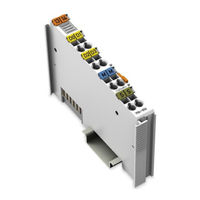
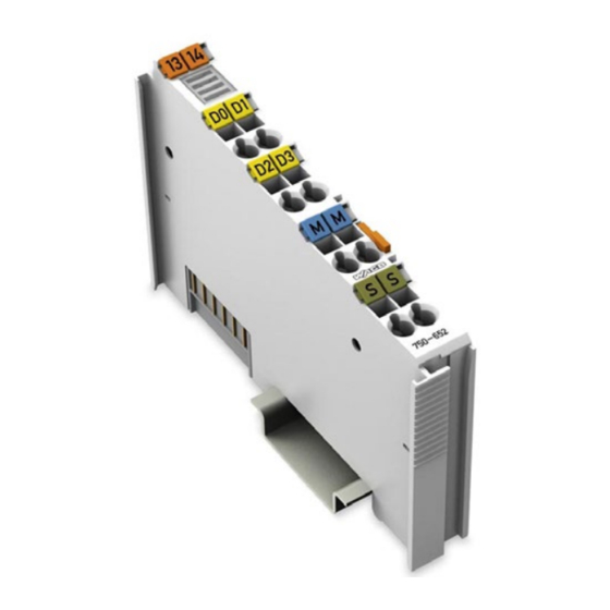
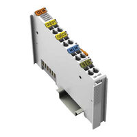
WAGO 750-652 Manual (82 pages)
I/O-SYSTEM 750
Brand: WAGO
|
Category: Recording Equipment
|
Size: 3 MB
Table of Contents
Advertisement
WAGO 750-652 Manual (82 pages)
Serial Interface RS-232 / RS-485
Brand: WAGO
|
Category: I/O Systems
|
Size: 2 MB
Table of Contents
Advertisement