Table of Contents
Advertisement
Quick Links
Operation
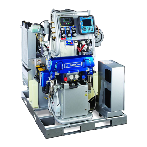
Reactor® 2 Elite Integrated
Proportioning System
Electric, Heated, Integrated Plural Component Proportioning System With Integrated Generator. For
spraying polyurethane foam and polyurea coatings. For professional use only. Not approved for use in
explosive atmospheres or hazardous locations. Not for outdoor use.
Important Safety Instructions. Read all warnings and instructions in
this manual. Save these instructions.
PROVEN QUALITY. LEADING TECHNOLOGY.
332636C
EN
Advertisement
Table of Contents

Related Manuals for Graco Reactor 2 Series


Summary of Contents for Graco Reactor 2 Series
- Page 1 Operation Reactor® 2 Elite Integrated Proportioning System 332636C Electric, Heated, Integrated Plural Component Proportioning System With Integrated Generator. For spraying polyurethane foam and polyurea coatings. For professional use only. Not approved for use in explosive atmospheres or hazardous locations. Not for outdoor use. Important Safety Instructions.
-
Page 2: Table Of Contents
Supply Wet Cups With Throat Seal Liquid Performance Charts..........87 (TSL) ..........46 Technical Specifications........90 Operation ............47 Initial System Setup ........47 Graco Extended Warranty for Integrated Register and Activate the Graco Insite ... 48 Reactor® 2 Components ....... 93 332636C... -
Page 3: Warnings
Warnings Warnings The following warnings are for the setup, use, grounding, maintenance, and repair of this equipment. The exclamation point symbol alerts you to a general warning and the hazard symbols refer to procedure-specific risks. When these symbols appear in the body of this manual or on warning labels, refer back to these Warnings. - Page 4 Warnings WARNING SKIN INJECTION HAZARD High-pressure fluid from gun, hose leaks, or ruptured components will pierce skin. This may look like just a cut, but it is a serious injury that can result in amputation. Get immediate surgical treatment. • Do not spray without tip guard and trigger guard installed. •...
- Page 5 Warnings WARNING THERMAL EXPANSION HAZARD Fluids subjected to heat in confined spaces, including hoses, can create a rapid rise in pressure due to the thermal expansion. Over-pressurization can result in equipment rupture and serious injury. • Open a valve to relieve the fluid expansion during heating. •...
- Page 6 Warnings WARNING EQUIPMENT MISUSE HAZARD Misuse can cause death or serious injury. • Do not operate the unit when fatigued or under the influence of drugs or alcohol. • Do not exceed the maximum working pressure or temperature rating of the lowest rated system component.
- Page 7 Warnings WARNING ENTAGLEMENT HAZARD Rotating parts can cause serious injury. • Keep clear of moving parts. • Do not operate equipment with protective guards or covers removed. • Do not wear loose clothing, jewelry or long hair while operating equipment. •...
-
Page 8: Important Isocyanate Information
Important Isocyanate Information Important Isocyanate Information Isocyanates (ISO) are catalysts used in two component materials. Isocyanate Conditions Keep Components A and B Separate Spraying or dispensing materials containing Cross-contamination can result in cured isocyanates creates potentially harmful mists, material in fluid lines which could cause serious vapors, and atomized particulates. - Page 9 Important Isocyanate Information Foam Resins with 245 fa Blowing Changing Materials Agents NOTICE Some foam blowing agents will froth at temperatures Changing the material types used in your above 90°F (33°C) when not under pressure, equipment requires special attention to avoid especially if agitated.
-
Page 10: Models
Models Models Reactor 2 E-30i All base systems include fluid inlet pressure and temperature sensors and Graco InSite . For part numbers, ™ Accessories, page No Air Compressor/Dryer With Air Compressor/Dryer Model E-30i E-30i with heat E-30i E-30i with heat Base Machine... - Page 11 Models Reactor 2 E-XP2i All base systems include fluid inlet pressure and temperature sensors and Graco InSite . For part numbers, ™ Accessories, page Model No Air Compressor/Dryer With Air Compressor/Dryer E-XP2i with heat E-XP2i with heat Base Machine 272081...
-
Page 12: Approvals
Approvals Approvals Note Heated hoses provided with a system or sold individually are not approved by Intertek. Intertek approvals apply to proportioning systems without hoses. Model Proportioning System Approvals: Accessories 272079 272089 Kit Number Description 15M483 Remote Display Module Protective Covers (10 pack) 15V551 ADM Protective Covers (10 pack) -
Page 13: Supplied Manuals
The following manuals are shipped with the Reactor. the Reactor. Refer to these manuals for detailed equipment information. Component Manuals in English: Manuals are also available at www.graco.com. Manual Description Manuals are available at www.graco.com. 332637 Reactor 2 Elite Integrated... -
Page 14: Typical Installation, Without Circulation
Typical Installation, without circulation Typical Installation, without circulation Figure 1 * Shown exposed for clarity. Wrap with tape during operation. Reactor Proportioner Fluid Supply Lines Heated Hose Feed Pumps Agitator Fluid Temperature Sensor (FTS) Heated Whip Hose Desiccant Dryer Fusion Spray Gun Bleed Lines Gun Air Supply Hose Gun Fluid Manifold (part of gun) -
Page 15: Typical Installation, With Circulation
Typical Installation, with circulation Typical Installation, with circulation Figure 2 * Shown exposed for clarity. Wrap with tape during operation. Reactor Proportioner Fluid Supply Lines Heated Hose Feed Pumps Fluid Temperature Sensor (FTS) Agitator Heated Whip Hose Desiccant Dryer Fusion Spray Gun Gun Fluid Manifold (part of gun) Gun Air Supply Hose Recirculation Lines... -
Page 16: Component Identification
Component Identification Component Identification Heated Hose Electrical Connectors Figure 3 Front View Main Power Switch Component A Pressure Relief Outlet Component A Pump Component B Pressure Relief Outlet Component B Pump (behind Electrical Drive Gear Housing Enclosure) Electrical Enclosure Proportioner Control Panel, page 19 Electric Motor Pallet Component A Fluid Manifold Inlet... - Page 17 Component Identification Temperature Control Module (TCM) Cable Figure 4 Back View Connections, page 31 Circulation Pump ISO Pump Lubricant Reservoir Electrical Cord Strain Relief Motor Control Module (MCM), page 28 Y-strainer (includes pressure Sight Glass gauge, temperature gauge, and Component A Control Valve pressure/temperature sensor) Component B Control Valve Booster Fluid Heater (not included with all...
-
Page 18: Generator
Component Identification Generator Diesel Fuel Tank Figure 5 Generator Power Distribution Box Air Filter Glow Plugs Battery (not supplied) Heat Exchanger Coolant Expansion Bottle Diesel Fuel Filter Heat Exchanger 12V Charge Alternator Heat Exchanger Coolant Fill Bottle Engine Coolant Expansion Bottle Oil Drain Engine Oil Filter... -
Page 19: Proportioner Control Panel
Component Identification Proportioner Control Panel Advanced Display Module (ADM), page 21 Engine Control Module, page 29 Component A Feed Pump Air Outlet Component B Feed Pump Air Outlet Agitator Air Outlet Gun Air Outlet Component A Feed Pump Air Regulator Component B Feed Pump and Agitator Air Regulator Gun Air Regulator... -
Page 20: Air Compressor
Component Identification Air Compressor Air Compressor Power Box Select models are supplied with an air compressor Air Compressor and Dryer On/Off Switch and air dryer. Refrigerated Air Dryer Air Dryer Drain Tube (bottom of refrigerated air dryer; not shown) Air Compressor Pressure Gauge Figure 7 332636C... -
Page 21: Advanced Display Module
Component Identification Advanced Display Module NOTICE To prevent damage to the softkey buttons, do not The ADM display shows graphical and text press buttons with sharp objects such as pens, information related to setup and spray operations. plastic cards, or fingernails. For detail on the display and individual screens, see Run Mode, page 53, or... - Page 22 Component Identification Table 1 : ADM Keys and Indicators Function Press to startup or shutdown the system. Startup/Shutdown Key and Indicator Press to stop all proportioner processes. This Is not a safety or emergency stop. Stop Press to select the specific screen or operation shown on the display directly next to each key.
- Page 23 Component Identification Module Status LEDs Figure 9 Back View Accessory Cable Connection Flat Panel Mount (VESA 100) Token Access Cover Model and Serial Number Battery Access Cover USB Port and Status LEDs CAN Cable Connection Table 2 ADM LED Status Descriptions Conditions Description System Status...
- Page 24 Component Identification ADM Display Details System Mode The current system mode is displayed at the lower Power Up Screen left of the menu bar. The following screen appears when the ADM is Alarm/Deviation powered up. It remains on while the ADM runs through initialization and establishes communication The current system error is displayed in the middle of with other modules in the system.
- Page 25 Component Identification Icons Screen Icons Softkey Icons The following icons appear in the ADM, directly to These are frequently used icons on the screens. the left or right of the soft key which activates that The following descriptions explain what each icon operation.
-
Page 26: Electrical Enclosure
Component Identification Electrical Enclosure AAA Temperature Control Module (TCM) AAB Motor Control Module (MCM) AAC Enclosure Fan AAD Circuit Breakers MP Main Power Switch 332636C... -
Page 27: Electrical Cabinet
Component Identification Electrical Cabinet AAM Hose Breaker AAN Transformer AAP Load Center AAS Fan AAU Wiring Terminal Blocks 332636C... -
Page 28: Motor Control Module (Mcm)
Figure 10 Load Center Description Pump Cycle Counter Module Status LEDs see LED Status Table Not Used CAN Communication Connections Graco Insite ™ Motor Temperature Motor Power Output Engine Coolant Temperature Main Power Input Heat Exchanger A Temperature Heat Exchanger B Temperature... -
Page 29: Engine Control Module
Component Identification Engine Control Module Icon Description Function Start Engine NOTICE Auto Auto mode (not To prevent damage to the softkey buttons, do not used) press buttons with sharp objects such as pens, plastic cards, or fingernails. Stop all system processes. -
Page 30: Load Center
Component Identification Load Center Related ON-State Color Component Description Fuel shutoff Fuel Shutoff Green solenoid on the Solenoid (FS) engine is open. Starter is Starter (ST) cranking. Glow Plugs Glow plugs are Green (GL) heating. Radiator Fan Radiator fan is Green (RF) A-side (red) -
Page 31: Connections
Component Identification Temperature Control Module (TCM) Cable Connections Module Status LEDs (see Figure 12 Advanced Display Module (ADM), page Power Input Boost Heater A Temperature (ISO) (CN) for conditions Heater Overtemperature Boost Heater B Temperature (RES) CAN Communications Connections Power Out (ISO) Hose Temperature Power Out (Res) Power Out (Hose) -
Page 32: Circuit Breakers
Not all wires are shown. CB03 15 A Boost Heat B CB04 30 A Hose Heat CB05 20 A Motor Control CB06* 40 A Air Compressor/Open CB07* 20 A Open 15 A CB08* Air Dryer/Open * Contact Graco for circuit breaker options. 332636C... - Page 33 Component Identification Circuit Breaker Configuration Options Improper configuration can result in electric shock. All electrical wiring must be done by a qualified electrician and comply with all local codes and regulations. See page 27 and 28 for correct circuit breaker configuration. Figure 14 Circuit Breakers Inside Proportioner Circuit Breakers, page 32 for recommended...
-
Page 34: Overview
Overview Overview The engine coolant loop (gray) circulates heated coolant from the engine (EE), through the heat exchanger (HE), radiator (ER), and back to the engine. Coolant in the proportioner coolant loop The system uses two coolant loops to use heat (black) captures heat from the engine coolant loop released from the engine to heat the A and B inside the heat exchanger (HE) near the radiator. - Page 35 Overview The proportioner coolant loop circulates coolant For models with a booster heater, the A and B through secondary heat exchangers (HE) located material enters the booster heater after the material on the back of the proportioner to heat the A is pressurized in the proportioning pumps to heat the and B component material before the material is material higher than 140°F (60°C).
- Page 36 Overview Coolant only flows through the secondary heat When the control valves (VA, VB) close, the A exchangers when the heat exchanger control valves and B material has reached target temperature. (VA, VB) are open and the A and B component Coolant flows through the bypass control valve (VC), temperatures are below the target temperatures set circulation pump (CP), sight glass (SG), proportioner...
-
Page 37: Setup
Setup Setup 3. Do not expose Reactor to rain or below 20°F (-7°C). NOTICE NOTICE To ensure the heat exchanger control valves Proper system setup, startup, and shutdown open and close properly, do not store Reactor procedures are critical to electrical equipment below 20°F (-7°C). -
Page 38: Trailer Setup Guidelines
Setup Trailer Setup Guidelines 2. Provide radiator exhaust for Reactor. Use a 400 (258,064 mm ) minimum louver. 3. Provide air duct to connect radiator exhaust to louver. 4. Provide a 400 in. ( 258,064 mm ) minimum fresh air intake louver near the generator. Route exhaust system away from combustible materials to prevent materials from igniting or gas 5. -
Page 39: Install Wall (Optional)
Setup Install Wall (optional) 3. Remove fuel tank from the pallet. a. Remove the mounting screws, supports, and It is only possible to install a wall between the spacers. proportioner and generator for systems without an air b. Disconnect inlet and outlet fuel lines from the compressor. - Page 40 Setup Figure 22 Top View With Wall Figure 23 Side View With Wall 332636C...
-
Page 41: Connect Battery
Setup Connect Battery Improper battery installation or maintenance may result in electric shock, chemical burns, or explosion. Battery maintenance must only Engine Starter Connections be performed or supervised by personnel Figure 25 knowledgeable of batteries and the required 3. Cover battery terminals with plastic caps (PC) precautions. -
Page 42: General Equipment Guidelines
Setup General Equipment Guidelines 5. Connect air lines to proportioner. Ensure components are properly connected to correct location. Maintain and inspect the generator, air compressor, and other equipment per the manufacturer recommendations to avoid an unexpected shutdown. Unexpected equipment shutdown will cause voltage fluctuations that can damage electrical equipment. -
Page 43: Connect Pressure Relief Lines
Setup Connect Pressure Relief Lines 2. Assemble heated hose sections, FTS, and whip hose. 3. Connect A and B hoses to A and B outlets on Reactor fluid manifold (FM). Hoses are color coded: red for component A (ISO), blue for component B (RES). -
Page 44: Close Gun Fluid Manifold Valves A And
Setup Close gun fluid manifold valves A and 5. Connect quick-disconnect pin fitting to 4 ft air hose, shipped loose. Connect other hose end to the gun air hose in the heated hose bundle. Push pin fitting into the lowest air panel outlet (PJ). Connect Whip Hose to Gun Or Gun Fluid Manifold See hose manual for proper connections. -
Page 45: Grounding
Setup Grounding The equipment must be grounded to reduce the risk of static sparking and electric shock. Electric or static sparking can cause fumes to ignite or explode. Improper grounding can cause electric shock. Grounding provides an escape wire for the electric current. -
Page 46: Supply Wet Cups With Throat Seal Liquid
• Component B (Resin) Pump: Check felt washers Liquid (TSL) in packing nut/wet-cup (S) daily. Keep saturated with Graco Throat Seal Liquid (TSL), Part No. 206995, to prevent material from hardening on displacement rod. Replace felt washers when worn or contaminated with hardened material. -
Page 47: Operation
Status LED is illuminated green, see Advanced Display Module (ADM), page 21. If 1. Turn the main power switch ON. The Graco logo the System Status LED is not green, press the will display until communication and initialization ADM Power On/Off (A) button . -
Page 48: Register And Activate The Graco Insite
Operation Register and Activate the Graco Insite 1. Go to www.GracoInSite.com, click on “InSite Login, then follow the instructions on the screen. Serial No. 2. Find and record the 15 digit serial number from the cellular box below. Verify Module Status To check the status of the cellular module, locate the status LEDs on the module then refer to the following chart. - Page 49 Operation Setup Mode The ADM will start in the Run screens at the Home screen. From the Run screens, press to access the Setup screens. The system defaults with no password, entered as 0000. Enter the current password then press .
-
Page 50: Advanced Setup Screens
Operation Advanced Setup Screens Advanced setup screens enable users to set units, adjust values, set formats, and view software information for each component. Press to scroll through the Advanced setup screens, Once in the desired Advanced setup screen, press to access the fields and make changes. When changes are complete press to exit edit mode. -
Page 51: System 1
Operation System 1 Recipes Use this screen to set the activation pressure for the Use this screen to add recipes, view saved recipes, and enable or disable saved recipes. Enabled Pressure Imbalance Alarm and Deviation, enable or recipes can be selected at the Home Run Screen. 24 disable diagnostic screens, set the maximum and minimum drum volume, and enable drum alarms. - Page 52 Operation Add Recipe 2. Use to highlight the next field and use the number pad to enter a value. Press to save. 1. Press and then use to select a recipe field. Press to enter a recipe name Enable or Disable Recipes (maximum 16 characters).
-
Page 53: Run Mode
Operation Run Mode The ADM will start in the Run screens at the “Home” screen. Press to navigate through the Run Mode screens. . Or press to access the Setup screens. Home — System Off Home — System With Error This is the home screen when the system is off. - Page 54 Operation Maintenance Events Use this screen to view daily and lifetime cycles or This screen shows the date, time, event code, and gallons that have been pumped and gallons or liters description of all events that have occurred on remaining in the drums. the system.
- Page 55 Operation System Events Use the table below to find a description for all system non-error events. All events are logged in the USB log files. Event Code Description Recipe Selected EACX EADA Heat On A EADB Heat On B EADH Heat On Hose EAPX Pump On...
- Page 56 Operation Errors Recipes This screen shows the date, time, error code, and Use this screen to add recipes, view saved recipes, description of all errors that have occurred on the and enable or disable saved recipes. Enabled system. recipes can be selected at the Home Run Screen. 24 recipes can displayed on the three recipe screens.
-
Page 57: Startup
Startup Startup 3. Check fluid inlet filter screens. Before daily startup, ensure that the fluid inlet screens are clean. See Flush Inlet Strainer Screen, page To prevent serious injury, only operate Reactor with all covers and shrouds in place. NOTICE Proper system setup, startup, and shutdown procedures are critical to electrical equipment reliability. - Page 58 Startup 8. For first startup of new system, set system 6. Press start button on the engine control settings on ADM in Setup Mode. module twice to start the generator. Verify Initial System Setup, page voltages are displayed on engine control module before moving to next step.
- Page 59 Startup 10. Start the air compressor, air dryer, breathing Circulation Through Reactor, page air, and other accessories. For systems with a If you need to circulate material through supplied air compressor: start the air compressor the heated hose to the gun manifold, see by pressing start on the air compressor START Circulation Through Gun Manifold, page box (CB).
- Page 60 Startup g. Hold gun fluid manifold over two grounded waste containers. Open fluid valves A and B until clean, air-free fluid comes from valves. Close valves. Thermal expansion can cause overpressurization, resulting in equipment rupture and serious injury, including fluid injection.
-
Page 61: Fluid Circulation
Fluid Circulation Fluid Circulation 3. Set PRESSURE RELIEF/SPRAY valves (SA, SB) to PRESSURE RELIEF/CIRCULATION Circulation Through Reactor NOTICE To prevent equipment damage, do not circulate fluid containing a blowing agent without consulting with your material supplier regarding fluid temperature limits. 4. -
Page 62: Circulation Through Gun Manifold
Fluid Circulation Circulation Through Gun Manifold rated at the maximum working pressure of this equipment. NOTICE 3. Follow procedures from Startup, page To prevent equipment damage, do not circulate fluid containing a blowing agent without consulting 4. Turn main power switch on with your material supplier regarding fluid temperature limits. -
Page 63: Spraying
Spraying Spraying 6. Verify that the engine temperature is at least up to the minimum operation temperature range. The fan will start running when the engine has reached maximum temperature. 7. Open fluid inlet valves. 1. Engage gun piston safety lock and close gun fluid inlet valves A and B. -
Page 64: Spray Adjustments
Spraying Spray Adjustments 10. Open gun fluid inlet valves A and B. Flow rate, atomization, and amount of overspray are affected by four variables. • Fluid pressure setting. Too little pressure results in an uneven pattern, coarse droplet size, low flow, and poor mixing. -
Page 65: Manual Hose Heat Mode
Spraying Manual Hose Heat Mode If the system produces the T6DH sensor error hose alarm or the T6DT sensor error TCM alarm, use manual hose heat mode until the hose RTD sensor can be repaired. Do not use Manual Hose Mode for extended periods of time. - Page 66 Spraying Disable Manual Hose Mode 2. Manual hose mode is automatically disabled when the system detects a valid RTD sensor in 1. Enter Setup Mode and navigate to System 2 the hose. Screen and deselect Enable Manual Hose Mode, or repair the hose RTD. 332636C...
-
Page 67: Shutdown
Shutdown Shutdown 3. Set PRESSURE RELIEF/SPRAY valves (SA, SB) to PRESSURE RELIEF/CIRCULATION Immediate Shutdown NOTICE To avoid system damage, follow daily shutdown procedure. Use only for immediate shutdown. For immediate shutdown, press: 4. Relieve pressure. Pressure Relief Procedure, page 5. Press to park the Component A Pump. - Page 68 Shutdown 8. Close the main air shutoff valve. 10. Press to stop the engine. 11. Close all fluid supply valves. 9. Turn main power switch OFF. Allow engine cooling dwell time prior to shutting down the engine. 12. Engage gun piston safety lock then close fluid inlet valves A and B.
-
Page 69: Pressure Relief Procedure
Pressure Relief Procedure Pressure Relief Procedure 4. Route fluid to waste containers or supply tanks. Turn PRESSURE RELIEF/SPRAY valves (SA, SB) to PRESSURE RELIEF/CIRCULATION Follow the Pressure Relief Procedure whenever you see this symbol. . Ensure gauges drop to 0. This equipment stays pressurized until pressure is manually relieved. -
Page 70: Flushing
Flushing Flushing To flush feed hoses, pumps, and heaters separately from heated hoses, set PRESSURE RELIEF/SPRAY valves (SA, SB) to PRESSURE RELIEF/CIRCULATION . Flush through bleed lines (N). To help prevent fire and explosion: • Flush equipment only in a well-ventilated area. •... -
Page 71: System Errors
System Errors System Errors Error Description Alarms A parameter critical to the process has reached System errors alert you of a problem and help a level requiring the prevent off-ratio spraying. When an error occurs the system to stop. The error information screen displays the active error alarm needs to be code and description. -
Page 72: Troubleshoot Errors
System Errors Troubleshoot Errors See system repair manual or visit help.graco.com causes and solutions to each error code. To troubleshoot the error: 1. Press the soft key next to “Help With This Error” for help with the active error. Note... -
Page 73: Maintenance
Coolant Levels Wetcup Check coolant level inside both overflow tanks daily. Check the wet cup daily. Keep it 2/3 full with Graco Throat Seal Liquid (TSL ) or compatible solvent. Do ® Flush and refill the coolant on both the engine and not overtighten packing nut/wet cup. -
Page 74: Clean Heat Sink Fins
Maintenance Clean Heat Sink Fins Engine Maintenance Keep heat sink fins clean at all times. Clean them The engine instructions that accompany your using a dry cloth or compressed air. unit detail specific procedures for maintenance of the engine. Following the engine manufacturer’s Note recommendations will extend engine work life. -
Page 75: Fuel Tank
Maintenance Fuel Tank 2. Place a container under the strainer base to catch drain off when removing the strainer plug (C). Fuel quality is critical to the performance and to the 3. Remove the screen (A) from the strainer service life of the engine. Water in the fuel tank manifold. -
Page 76: Pump Lubrication System
Maintenance Pump Lubrication System 4. When the reservoir is flushed clean, fill with fresh lubricant. Check the condition of the ISO pump lubricant daily. 5. Thread the reservoir onto the cap assembly and Change the lubricant if it becomes a gel, its color place it in the bracket. -
Page 77: Usb Data
USB Data USB Data • Event Description Event codes include both error codes (alarms, deviations, and advisories) and record only events. Each time a USB flash drive is inserted into the ADM USB port, a new folder named DATAxxxx is created. Actions Taken includes setting and clearing event The number at the end of the folder name increases conditions by the system, and acknowledging error... -
Page 78: System Configuration Settings
The Blackbox log maintains a record of how the system runs and the features that are used. This log The daily log file name is 3–DAILY.CSV and is stored will help Graco troubleshoot system errors. in the DATAxxxx folder. Diagnostics Log File... -
Page 79: Download Log Files
If it does not, open USB flash drive from within Windows® Explorer. • U+0020 - U+007E (Basic Latin) 6. Open GRACO folder. • U+00A1 - U+00FF (Latin-1 Supplement) 7. Open the system folder. If downloading data • U+0100 - U+017F (Latin Extended-A) from more than one system, there will be more •... -
Page 80: Upload Procedure
Upload Procedure, page 80 folder within the GRACO folder. Each folder is to install the file. labeled with the corresponding serial number of the ADM. (The serial number is on the back of The format of the custom language file is critical. -
Page 81: Appendix A: Engine Control Module
Appendix A: Engine Control Module Appendix A: Engine Control Module Run Screens There are seven run screens on the engine control module: • Line-to-neutral voltage • Line-to-line voltage • Frequency • Engine Speed • Engine lifetime counter • Battery voltage Press to scroll through the run screens. - Page 82 Appendix A: Engine Control Module Mode Icons Icon Description Details Engine is at rest and the unit is in stop mode. Stopped Auto Engine is at rest and the unit is in auto mode. Manual Engine is at rest and the unit is in manual run mode. Timer animation Engine is starting up.
- Page 83 Appendix A: Engine Control Module Alarms There are two types of alarms that can occur on the system. Alarms are indicated by an icon the Run and Information screens. See the information screen to see the latest alarm. Warning When present on system, a warning alarm will stop the generator. Shutdown When present on system, a shutdown alarm will stop the generator.
-
Page 84: Dimensions
Dimensions Dimensions Figure 332636C... - Page 85 Dimensions Figure 36 Figure 37 332636C...
- Page 86 Dimensions Figure 38 Floor Mount Hole Pattern 332636C...
-
Page 87: Performance Charts
Performance Charts Performance Charts Use these charts to help identify the proportioner that will work most efficiently with each mix chamber. Flow rates are based on a material viscosity of 60 cps. NOTICE To prevent system damage, do not pressurize the system above the line for the gun tip size being used. Proportioners For Foam 2000 (138) - Page 88 Performance Charts Proportioners For Coatings Table 4 Fusion Air Purge, Round Pattern 3500 (241) 3000 (207) 2500 AR2020 E-XP2i (172) (000) PRESSURE AR2929 2000 (00) psi (bar) (138) 1500 (103) AR4242 (01) 1000 (69) (34) (1.9) (3.8) (5.7) (7.6) FLOW gal./min (l/min) Table 5 Fusion Air Purge, Flat Pattern 3500 (241, 24.1)
- Page 89 Performance Charts Table 6 Fusion Mechanical Purge, Round Pattern 3500 (241, 24.1) E-XP2i 3000 (207, 20.7) XR2323 (RTM040) 2500 (174, 17.4) XR2929 (RTM040) PRESSURE 2000 (138, 13.8) psi (bar) MR3535 (RTM040) 1500 MR4747 (103, 10.3) (RTM055) XR3535 (RTM055) XR4747 1000 (RTM055) (69, 6.9) (35, 3.5)
-
Page 90: Technical Specifications
Technical Specifications Reactor 2 Elite Integrated Proportioning Systems U.S. Metric Maximum Fluid Working Pressure E-30i 2000 psi 14 MPa, 140 bar E-XP2i 3500 psi 24.1 MPa, 241 bar Maximum Fluid Temperature E-30i 150°F 65°C E-30i with booster heater 180°F 82°C E-XP2i 180°F 82°C... - Page 91 Recommended Battery Size BC Group Number Length 10.25 in. 260 mm Width 6.81 in. 173 mm Height 7.88 in. 200 mm Booster Heater Power E-30i None E-30i with booster heat 4000 Watts E-XP2i 4000 Watts Rotary Vane Air Compressor Hydrovane Model V04 (PURS type), continuous run Part No.
- Page 92 Weight E-30i 1750 lb 794 kg E–30i with compressor and dryer 2200 lb 998 kg E-30i with booster heat 1800 lb 816 kg E–30i with booster heat, 2250 lb 1021 kg compressor, and dryer E-XP2i 1800 lb 816 kg E–XP2i with compressor and 2200 lb 998 kg dryer...
-
Page 93: Graco Extended Warranty For Integrated
With the exception of any special, extended, or limited warranty published by Graco, Graco will, for a period of twelve months from the date of sale, repair or replace any part of the equipment determined by Graco to be defective. This warranty applies only when the equipment is installed, operated and maintained in accordance with Graco’s written recommendations. - Page 94 Graco Information For the latest information about Graco products, visit www.graco.com. To place an order, contact your Graco Distributor or call to identify the nearest distributor. Phone: 612-623-6921 or Toll Free: 1-800-328-0211 Fax: 612-378-3505 All written and visual data contained in this document reflects the latest product information available at the time of publication.
Need help?
Do you have a question about the Reactor 2 Series and is the answer not in the manual?
Questions and answers