Table of Contents
Advertisement
Instructions
™
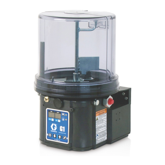
G1
Standard
Lubrication Pump
For dispensing of NLGI Grades #000 to #2 greases and oil with at least 40cSt. For
Professional Use Only.
Not approved for use in explosive atmospheres or hazardous locations.
Part Nos., page 3
5100 psi (35.1 MPa, 351.6 bar) Maximum Working Pressure
Important Safety Instructions
Read all warnings and instructions in this
manual. Save these instructions.
332316E
3132066
conforms to AN-
SI/UL 73
certified to
CAN/CSA
Std. 22.2 No 68-09
EN
Advertisement
Table of Contents

Related Manuals for Graco G1


Summary of Contents for Graco G1
- Page 1 Instructions ™ Standard 332316E Lubrication Pump For dispensing of NLGI Grades #000 to #2 greases and oil with at least 40cSt. For Professional Use Only. Not approved for use in explosive atmospheres or hazardous locations. Part Nos., page 3 5100 psi (35.1 MPa, 351.6 bar) Maximum Working Pressure Important Safety Instructions Read all warnings and instructions in this manual.
-
Page 2: Table Of Contents
Notes ........31 Graco Standard Warranty ....32... -
Page 3: Grease Models
Grease Models Grease Models Reservoir Size Voltage Model Wiper Follower 2 Liter 4 Liter 8 Liter 12V DC 24V DC 100-240 Level 94G006 94G007 94G008 94G009 94G010 94G011 94G018 94G019 94G020 94G021 94G022 94G023 94G036 94G037 94G038 94G039 94G040 94G041 94G063 94G064 94G065... -
Page 4: Warnings
Warnings Warnings The following warnings are for the setup, use, grounding, maintenance, and repair of this equipment. The exclama- tion point symbol alerts you to a general warning and the hazard symbols refer to procedure-specific risks. When these symbols appear in the body of this manual or on warning labels, refer back to these Warnings. Product-specific hazard symbols and warnings not covered in this section may appear throughout the body of this manual where applicable. - Page 5 Warnings WARNING SKIN INJECTION HAZARD High-pressure fluid from dispensing device, hose leaks, or ruptured components will pierce skin. This may look like just a cut, but it is a serious injury that can result in amputation. Get immediate surgical treatment. •...
-
Page 6: Installation
Installation Installation Grounding The equipment must be grounded. Grounding reduces the risk of electric shock by providing an escape wire for the electrical current in the event of malfunction or breakdown. Component Identification Oil Models Grease Models with Follower Plate Grease Models . -
Page 7: Typical Installation
• Refer to the two mounting hole layouts provided • If the G1 grease model is going to be operated in the Mounting Pattern section of this manual, in a tilted or inverted position for any period of page 30. -
Page 8: System Configuration And Wiring
This product must be avoid equipment damage: installed by a qualified electrician in compliance with • Never operate G1 Pump DC models without a fuse all state and local codes and regulations. installed. If the product is permanently connected: •... - Page 9 Wiring and Installation Diagrams NOTE: Graco does not provide a power cable with the G1. Power cables are available for purchase from Graco or the user may provide their own. See Table 1 for reference pages containing additional information related to Graco power cables.
- Page 10 Installation Power DIN AC - 15 foot: Part No. 123358 Din Connector Specifications • DIN 43650 Form A, 18 mm, assembled to power cable manufacturer’s instructions • Rated to 6 Amps minimum at 250V AC Cable Specifications • United States/Canada: 3 conductor 16 AWG UL62 and CSA 22.2 No. 49 listed SOOW cable with black, white, green insulation •...
- Page 11 Installation Connector on Housing Connector on Cable Example Wiring Diagram 332316E...
- Page 12 Installation Power DIN DC- 15 foot: Part No. 123358 NOTICE Be sure when power is applied that stirring paddle rotates clockwise (when viewed from the top). If it is wired incorrectly paddle could rotate counter-clockwise which will damage the pump’s internal components. If this happens, stop the pump immediately and wire unit correctly.
- Page 13 Installation Connector on Cable Connector on Housing Example Wiring Diagram Ignition Switch Fuse 12V-pump - 7.5A - Graco kit #571039 24V pump - 4A - Graco kit #571040 332316E...
- Page 14 Installation Power CPC DC- 15 foot: Part No. 127783 CPC Connector Specifications • One, 7-position, 1.5 mm socket connector AMP 967650-1 • Three, 16 - 14 gauge female pins AMP 962999-1 • One, 180-degree strain relief or one, 90-degree strain relief AMP 965576-1 (determined by cable exit for cable configuration) Installation Notes •...
- Page 15 Installation Connector on Housing Connector on Cable Example Wiring Diagram Ignition Switch Fuse 12V-pump - 7.5A - Graco kit #571039 24V pump - 4A - Graco kit #571040 332316E...
- Page 16 Installation Part No. 124333: Part No. 124300: Cable Pin Out (M12) (F . 6) Field Wireable Pin Out (M12) (F . 7) Wire Colors Wire Colors Item No. Color Item No. Color Brown Brown White White Blue Blue Black Black &DEOH 3LQ 2XW )LHOG :LUHDEOH 3LQ 2XW )HPDOH (QG 9LHZ...
- Page 17 Installation Part No. 124594: Part No. 124595: 4 Pin Eurofast Field Wireable Connector 5 Pin Eurofast Field Wireable Connector . 8) . 9) 332316E...
-
Page 18: Setup
G1 pump from damage. • Only use a pressure relief valve that is rated for no more than the working pressure of the G1 pump it is installed on. See Technical Data, page 29. • Install a pressure relief valve before any auxiliary fitting. -
Page 19: Loading Grease
Loading Grease 3. Fill reservoir with NLGI grease to max fill line. NOTE: Vent port, located in rear of reservoir, should not To ensure optimal performance from the G1: be used as an overfill port/indicator. • Only use NLGI #000 - #2 greases appropriate for your application, automatic dispensing, and the equipment’s operating temperature. -
Page 20: Filling Oil Unit
• Do not overfill (F . 14). • Do not operate G1 without reservoir attached. • Only use oils with viscosity at least 40 cSt. . 15 2. Only run pump until air is no longer dispensed with the lubricant coming out of element fitting (F . -
Page 21: No Controller Operation
No Controller Operation No Controller Operation The G1 Pump can be controlled using an external, user Low Level Output Option supplied, power source and controller. Some G1 pumps without controllers include a Low Level Output Option. The low level signal is monitored across Refer to the Typical Installation diagrams provided on PINS 3 and 4. - Page 22 No Controller Operation Oil Pumps To ensure that a low level condition has been met, the low level trigger must be detected for 10 continuous sec- When the oil level has reached a low warning level, onds. PINS 3 and 4 close, sending the signal to the controller that the fluid has reached a low level.
-
Page 23: Troubleshooting
Lubricant leaks past seal located on the filling bottom of the reservoir If problem persists, contact Graco Cus- tomer Service or your local Graco dis- tributor for assistance. Air is trapped in the reservoir between Add grease following Loading Grease... -
Page 24: Maintenance
Keep all fittings clean using a clean dry cloth. Dirt and/or debris can damage pump and/or lubrication system. Daily G1 Pump Unit and Reservoir Keep pump unit and reservoir clean using a clean dry cloth. Monthly External Wiring Harness Verify external harnesses are secure. -
Page 25: Parts Drawing: 2 Liter Models
Parts Drawing: 2 Liter Models Parts Drawing: 2 Liter Models Oil Reservoir Low Level Grease Models Only Follower Plate Models Only Low Level Oil Models Only Torque to 4 in. lbs (0.45 N.m) Torque to 30 in. lbs (3.4 N.m) Torque to 50 in. -
Page 26: Parts Drawing: 4 And 8 Liter Models
Parts Drawing: 4 and 8 Liter Models Parts Drawing: 4 and 8 Liter Models Oil Reservoir Low Level Grease Models Only Follower Plate Models Only Low Level Oil Models Only Torque to 4 in. lbs (0.45 N.m) Torque to 30 in. lbs (3.4 N.m) Torque to 50 in. -
Page 27: Parts
Parts Parts Part No. Description Qty. Part No. Description Qty. BASE, molded 278139 SEAL, follower plate, 2 liter models 278142 BOTTOM, cover 16F472 SEAL, follower plate, 4 liter models 115477 SCREW, bottom cover O-RING, 258 (green), included in Kit 16V763 SEAL, follower plate, 8 liter models 124396 571042, 571043, 571044, 571045,... -
Page 28: Pressure Relief Valves
Valve 16C807. 571039 FUSE, 12 volt DC Pressure Relief Valve 16C807 can only be used on the G1 and G3 Pumps. It is not intended for use with 571040 FUSE, 24 volt DC any other products. The pressure relief valve uses a... -
Page 29: Technical Data
Technical Data Technical Data Maximum Working Pressure 5100 psi (35.1 MPa, 351.6 bar) Power 100-240 VAC 88 - 264 VAC; 0.8 A current, 90 VA Power, 47/63 Hz, Single phase, inrush/locked rotor, max 40A (1ms) 12 VDC 9 - 16 VDC; 5 A current, 60 W, inrush/locked rotor 12 A 24 VDC 18 - 32 VDC;... -
Page 30: Mounting Pattern
Technical Data Mounting Pattern For correct mounting configuration, choose either Option 1 or Option 2. See Part Number 126916 template. Option 1 0.367inch 7.087 inch 9.3 mm 180.0 mm 2x Ø 0.366 inch 1.180 inch 9.3 mm 30.0 mm 3.268 inch 83.0 mm 3.544 inch 90.0 mm... -
Page 31: Notes
Notes Notes 332316E... -
Page 32: Graco Standard Warranty
With the exception of any special, extended, or limited warranty published by Graco, Graco will, for a period of twelve months from the date of sale, repair or replace any part of the equipment determined by Graco to be defective.
Need help?
Do you have a question about the G1 and is the answer not in the manual?
Questions and answers