Table of Contents
Advertisement
Quick Links
Operation, Repair, Parts
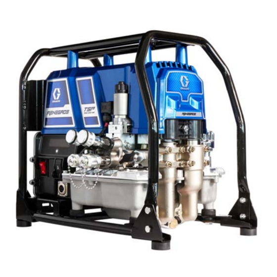
Renegade TSP
Torque Series Pump
Renegade TSP is a hydraulic power pack for use with bolt torquing wrenches only.
For professional use only.
Not approved for use in explosive atmospheres or hazardous (classified) locations.
Models: 17U632, 17U633, 17U634, 17U635
10,000 psi (68.9 MPa, 700 bar) Maximum Working Pressure
Important Safety Instructions
Read all warnings and instructions in this manual and on the unit before using
the equipment. Be familiar with the controls and the proper usage of the
equipment. Save these instructions.
3A6884B
EN
Advertisement
Table of Contents

Related Manuals for Graco Renegade Series


Summary of Contents for Graco Renegade Series
- Page 1 Operation, Repair, Parts Renegade TSP 3A6884B Torque Series Pump Renegade TSP is a hydraulic power pack for use with bolt torquing wrenches only. For professional use only. Not approved for use in explosive atmospheres or hazardous (classified) locations. Models: 17U632, 17U633, 17U634, 17U635 10,000 psi (68.9 MPa, 700 bar) Maximum Working Pressure Important Safety Instructions Read all warnings and instructions in this manual and on the unit before using...
-
Page 2: Table Of Contents
Graco Standard Warranty ........ -
Page 3: Models
Models Models Model Maximum Working Pressure Name Voltage Pendant psi (MPa, bar) 120V Renegade TSP 17U632 Corded 10,000 psi (68.9 MPa, 700 bar) Torque Series Pump 120V Renegade TSP 17U633 Wireless 10,000 psi (68.9 MPa, 700 bar) Torque Series Pump 230V Renegade TSP 17U634... -
Page 4: Warnings
Warnings Warnings The following warnings are for the setup, use, grounding, maintenance, and repair of this equipment. The exclamation point symbol alerts you to a general warning and the hazard symbols refer to procedure-specific risks. When these symbols appear in the body of this manual or on warning labels, refer back to these Warnings. - Page 5 Check hoses and couplings daily. Replace worn or damaged parts immediately. • This system is capable of producing 10,000 psi (68.9 MPa, 700 bar). Use Graco replacement parts or accessories that are rated at a minimum of 10,000 psi (68.9 MPa, 700 bar).
- Page 6 Warnings WARNING ELECTRIC SHOCK HAZARD This equipment must be grounded. Improper grounding, setup, or usage of the system can cause electric shock. • Turn off and disconnect extension cord before servicing equipment. • Connect only to grounded electrical outlets. • Use only 3-wire extension cords.
-
Page 7: Component Identification
Component Identification Component Identification Manual Advance Switch Pendant M On/Off Switch Oil Fill Cap (Breather) Display Oil Level Sight Display Button Electrical Inlet Wireless Remote Signal Indicator 15/20A Switch (120V only) Pendant Advance Switch Pressure Relief Button Pressure Gauge Port Pressure Setting Valve Pump Stop Switch Hose Connection –... -
Page 8: Controls And Indicators
Component Identification Controls and Indicators Item Description On/Off Switch Turns TSP power pack on or off. 15A/20A Switch Sets TSP power pack to either 15A or 20A. Select setting based on your circuit rating. Select 20A when a 20A circuit is available. Using the (120V only) 20A setting provides the maximum performance. -
Page 9: Grounding
Grounding Grounding Power Requirements 100-120 VAC, 50/60 Hz, 15A/20A, single phase. The equipment must be grounded to reduce the risk of electric shock. Improper 220-240 VAC, 50/60 Hz, 10A, single phase. grounding can cause electric shock. Grounding provides an escape wire for the electric current. -
Page 10: Pressure Relief Procedure
Pressure Relief Procedure Pressure Relief Procedure Follow the Pressure Relief Verify displayed pressure goes to zero when motor stops. Procedure whenever you see this symbol. If pressure is not zero, then press Pressure Relief Button. To help prevent serious injury from pressurized fluid, such as skin injection, splashing fluid and moving parts, follow the Pressure Relief Procedure before... -
Page 11: Setup
Setup Setup Pendant Setup Fill Oil Tank Unit is shipped without hydraulic oil. Before Corded Pendant the first use, fill tank with hydraulic oil, see Recommended Oil Temperature Ranges Attach Corded Pendant by lining up the tab for Various Hydraulic Oil Weights page 52. on the plug with the socket located on the power pack control. -
Page 12: Modes
Setup Modes Cycle through primary menu by short pressing the control Display Button until PRIME appears on Display. The TSP power pack has three modes: prime, calibration, and operation. The prime mode removes air from the pump. calibration mode calibrates pressure sensor. -
Page 13: Connect Hose And Tool
Setup Connect Hose and Tool Hose Prime Procedure Prime and flush the hoses each time a hose The TSP power pack uses flush-face is replaced or when swapping tools. quick-release couplings that are durable and Continuous use of a hose and tool easy to clean. -
Page 14: Operation
Operation Operation AMPUTATION OR CRUSH HAZARD FIRE AND EXPLOSION WARNING Unexpected pump activation can cause To avoid serious injury, do not use in serious injury. Ensure hands are clear of explosive atmospheres or hazardous wrench crush points when activating TSP (classified) locations. -
Page 15: Shut Down
Operation Shut Down Cleaning Turn ON/OFF switch to OFF position. Proper care maintenance Unplug the TSP power pack. recommended for best experience with the TSP power pack. For proper maintenance Disconnect hoses from TSP power pack. activity and intervals, see Maintenance page To clean, wipe TSP power pack and hoses with a rag to remove any accumulated oil and dirt after every use. -
Page 16: Display
Display Display Main Menu Operation Short press Display Button and LIFETIME HOURS will scroll past on screen. Turn power ON. Display will show as unit powers on. NOTE: LIFETIME HOURS displays a lifetime hour meter and cannot be reset. Once powered on, Display will show PRESSURE (in PSI, bar, or MPa - as Short press Display Button and name of... -
Page 17: Change Display Units
Display Change Display Units Select Control Device NOTE: To change display units you must be Short press Display Button three times to in the pressure screen with the pressure move to SELECT CONTROL DEVICE display at zero. mode. Press and hold the Display Button for 5 seconds to change pressure units (psi, bar, MPa) to desired units. -
Page 18: Secondary Menu (Stored Data)
Display Secondary Menu (Stored Short press Display Button and SOFTWARE REVISION scrolls past on Data) the Display. NOTE: Secondary Menu contains the calibration procedure plus information that may be useful during troubleshooting or repair. To enter Secondary Menu turn power switch on while holding Display Button. -
Page 19: Maintenance
Maintenance Maintenance Routine maintenance is important to ensure proper operation of your TSP power pack. Maintenance includes performing routine actions that keep your TSP power pack in operation and prevent trouble in the future. Activity Interval Inspect pump, hoses, and tools for damage or leaks. Daily. -
Page 20: Troubleshooting
Troubleshooting Troubleshooting Follow Pressure Relief Procedure page 10, before troubleshooting or repairing TSP power pack. Check all possible problems and causes before disassembling TSP power pack. Problem Cause Solution Unit does not start when plugged in Extension cord. Check Replace extension cord. and power switch is “ON”. - Page 21 Troubleshooting Problem Cause Solution Maximum pressure is ~3,300 psi. High pressure pump issue. Replace high pressure pump, see Pump Replacement page 30. Unit runs slow. Air in hydraulic system. Check oil level and fill as needed. Perform Prime TSP Power Pack Procedure page 12 and Hose Prime Procedure page 13.
- Page 22 Troubleshooting Problem Cause Solution TSP power pack does not run at all. Control board detected Set TSP power pack to OFF and disconnect power to TSP power voltage surges. pack. Display shows CODE 04. Locate a good voltage supply to prevent damage to electronics.
- Page 23 Troubleshooting Problem Cause Solution 3A6884B...
- Page 24 Troubleshooting Problem Cause Solution TSP power pack does not run at all. Control is commanding Perform Field Short Test: Test at large 6-pin motor field connector. motor to run, but motor shaft There should not be continuity from Display shows CODE 05. does not rotate.
- Page 25 Troubleshooting Problem Cause Solution TSP power pack does not run at all. Motor overheated. Note: Motor must be cooled down for the test. Display shows CODE 06. Keep TSP power pack in cooler location with good ventilation. Make sure motor air intake is not blocked. Set TSP power pack to OFF and disconnect power to TSP power pack.
- Page 26 Troubleshooting Problem Cause Solution TSP power pack does not run at all. Incoming voltage too low for Set TSP power pack to OFF and disconnect power to TSP power TSP power pack operation. pack. Display shows CODE 08. Remove other equipment that uses the same circuit.
- Page 27 Troubleshooting Problem Cause Solution TSP power pack does not run at all. Motor position sensor not Set TSP power pack to OFF and disconnect power to TSP power working. pack. Display shows CODE 16. Open control box by removing 8 screws that attach control assembly to control box.
-
Page 28: Repair
Repair Repair Calibration Procedure Enter the secondary menu, see Secondary Menu (Stored Data) page The TSP power pack should be re-calibrated after replacing the transducer or control assembly. The TSP power pack should also be re-calibrated as needed based on your company’s business practices and if you suspect the TSP power pack is not operating correctly. - Page 29 Repair Press the TSP power pack Advance NOTE: If the calibration procedure was Switch. Set pressure to 8000 psi per the unsuccessful, the following message will calibration gauge or data acquisition scroll on the Display: CALIBRATION system. While keeping the power pack FAILED.
-
Page 30: Pump Removal
Repair Pump Replacement Tools Required: 13 mm wrench. Remove pump bolts (qty 6). Pump Removal (High flow displacement pump shown) Pump removal includes disassembling the pump guard and pump bolts and removing the pump. Perform Pressure Relief Procedure, page 10 and disconnect power to the TSP power pack. -
Page 31: Pump Installation
Repair Pump Installation Slide pump assembly into drive housing while ensuring the piston rod head is properly aligned in the assembly (High flow displacement pump shown) housing. Pump installation includes securing the pump and connecting to the fluid inlet and outlet. Install pump tank o-ring and manifold seals. -
Page 32: 2-Way, Poppet Valve Replacement
Repair 2-Way, Poppet Valve Attach pump housing to manifold with four screws and flat washers. Torque Replacement screws to 50-70 in-lbs. (5.6-7.9 N • Tools Required: Phillips screwdriver, 7/8 in. wrench, 3/4 in. wrench. Perform Pressure Relief Procedure, page 10 and disconnect power to the TSP power pack. -
Page 33: Pressure Set Valve Replacement
Repair Pressure Set Valve Lift the black solenoid to gain clearance to the 7/8 in. hex on the body of the Replacement poppet valve. Loosen and remove. Tools Required: 1-1/16 in. wrench. Perform Pressure Relief Procedure, page 10 and disconnect power to the TSP power pack. -
Page 34: 4-Way Valve Replacement
Repair 4-Way Valve Replacement Remove finger-tight nut on top of valve. Remove coil from valve. Tools Required: Phillips screwdriver, 5 mm Allen wrench, 10 mm wrench. Remove 4-Way Valve Perform Pressure Relief Procedure, page 10 and disconnect power to the TSP power pack. - Page 35 Repair Install 4-Way Valve Use a 5 mm Allen wrench to remove the three M6 screws that secure the diverter Remove finger-tight nut on top of new block to the manifold. Remove the valve. Remove coil from new valve. diverter block. Using a 5 mm Allen wrench, carefully separate the 4-way valve from the diverter block.
- Page 36 Repair Ensure new o-rings are installed in Position the 4-way valve on the diverter diverter block and remain in place. block, it will only fit in one position. Position diverter block on the manifold. Secure with the four M6 screws. Torque Align the three screws in the diverter to 6-8 ft-lbs (8.1-10.8 N•m).
-
Page 37: Transducer Replacement
Repair Transducer Replacement Install Transducer Apply sealant to transducer threads. Tools Required: 15/16 in. wrench. Start threading transducer into the manifold. Remove Transducer Using a 15/16 in. socket, tighten transducer to 50-55 ft-lbs (68.8-75.6 Perform Pressure Relief Procedure N•m). page 10 and disconnect power to the TSP power pack. -
Page 38: Pendant Battery Replacement
Pendant Battery Replacement Pendant Battery Replacement CR123A BATTERY 3A6884B... -
Page 39: Hydraulic Schematic
Hydraulic Schematic Hydraulic Schematic Part Description Part Description 19Y114 KIT, repair, manifold 19Y104 PUMP, high pressure 19Y107 KIT, valve, 4-way, directional 195695 FILTER, fluid 19Y110 KIT, valve, manual pressure set 19Y214 FITTING, filter, 1/4 NPT male 19Y353 VALVE, 2-way, poppet 17U673 FITTING, QD, male, high pressure... -
Page 40: Wiring Diagram - 120V
Wiring Diagram - 120V Wiring Diagram - 120V See Control Box Parts - 120V page 48 for 120V control box wiring Part Description Part Description 19Y111 KIT, motor, hydraulic power 120660 SWITCH, rocker pack 19Y107 KIT, valve, 4-way, directional 17U610 BOX, control (120V) 19Y353 VALVE, 2-way, poppet 19Y115 ASSEMBLY, control... -
Page 41: Wiring Diagram - 230V
Wiring Diagram - 230V Wiring Diagram - 230V See Control Box Parts - 230V page 50 for 230V control box wiring Part Description Part Description 19Y111 KIT, motor, hydraulic power 120660 SWITCH, rocker pack 19Y107 KIT, valve, 4-way, directional 17U629 BOX, control (230V) 17U666 Valve, 2-way, poppet 19Y115 ASSEMBLY, control... -
Page 42: Renegade Tsp Torque Series Pump Parts
Renegade TSP Torque Series Pump Parts Renegade TSP Torque Series Pump Parts Ref. Torque Ref. Torque Ref. Torque 20-25 ft-lbs (27.1-33.4 N•m) 30-40 in-lbs (3.4-4.5 N•m) 110-120 in-lbs (12.4-13.6 N•m) 40-45 in-lbs (5.1-6.2 N•m) 10-12 in-lbs (1.1-1.4 N•m) 95-105 in-lbs 40-45 in-lbs (4.5-5.1 N•m) (10.7-11.9 N•m) 3A6884B... - Page 43 Renegade TSP Torque Series Pump Parts Renegade TSP Torque Series Pump Parts List Ref. Part Description Qty. Ref. Part Description Qty. PENDANT, complete 19Y111 KIT, motor, hydraulic 19Y103 WIRED power pack 19Y102 WIRELESS includes 100132 WASHER, flat CR123A battery 119695 DAMPENER, engine 18A681 MAGNET, lanyard...
-
Page 44: Manifold Assembly Parts
Manifold Assembly Parts Manifold Assembly Parts Ref. Torque Ref. Torque 50-55 ft-lbs (68.8-75.6 N•m) 6-8 ft-lbs (8.1-10.8 N•m) 57-61 ft-lbs (77-83 N•m) 19-21 ft-lbs (25.8-28.5 N•m) 4-5 ft-lbs (5.4-6.8 N•m) 3A6884B... - Page 45 Manifold Assembly Parts Manifold Assembly Parts List Ref. Part Description Qty. Ref. Part Description Qty. 52† 557897 O-RING, -010, 90d, 19Y114 KIT, repair, manifold buna 19Y107 KIT, valve, 4-way, 53† 104282 O-RING, packing directional 19Y113 KIT, manifold, 19Y110 KIT, valve, manual, distribution pressure set 17U671...
-
Page 46: Motor Assembly Parts
Motor Assembly Parts Motor Assembly Parts Ref. Torque Ref. Torque Ref. Torque 190-210 in-lbs 95-105 in-lbs 10-12 in-lbs (1.1-1.4 N•m) (21.5-23.7 N•m) (10.7-11.9 N•m) 20-25 ft-lbs (27.1-33.4 N•m) 5-7 ft-lbs (6.8-9.5 N•m) 40-45 ft-lbs (54.2-61.0 N•m) 50-70 in-lbs (5.6-7.9 N•m) 145-155 in-lbs 57-61 ft-lbs (77-83 N•m) (16.4-17.5 N•m) - Page 47 Motor Assembly Parts Motor Assembly Parts List Ref. Part Description Qty. Ref. Part Description Qty. 17U730 FITTING, indicator, 19Y111 KIT, motor, hydraulic fluid level power pack 17U731 CAP, breather, fill 116074 WASHER, thrust 17U732 O-RING, 382, 70A 107434 BEARING, thrust 17U733 PLUG, drain 19Y112...
-
Page 48: Control Box Parts - 120V
Control Box Parts - 120V Control Box Parts - 120V Ref. Torque Ref. Torque 10-12 in-lbs (1.1-1.4 N•m) 15-20 in-lbs (1.7-2.3 N•m) 17-21 in-lbs (1.9-2.4 N•m) 40-45 in-lbs (4.5-5.1 N•m) 3A6884B... - Page 49 Control Box Parts - 120V Control Box Parts List Ref. Part Description Qty. Ref. Part Description Qty. 17U620 PLATE, backer, 278893 BOX, control, 120V pendant connection 17U638 BOARD, assembly, 19Y411 COVER, connector display 17U645 SEAL, panel 114528 SCREW, mach, 17U614 SWITCH, rocker, Phillips, PNHD advance...
-
Page 50: Control Box Parts - 230V
Control Box Parts - 230V Control Box Parts - 230V Ref. Torque Ref. Torque 10-12 in-lbs (1.1-1.4 N•m) 15-20 in-lbs (1.7-2.3 N•m) 17-21 in-lbs (1.9-2.4 N•m) 3A6884B... - Page 51 Control Box Parts - 230V Control Box Parts List Ref. Part Description Qty. Ref. Part Description Qty. 17U727 HARNESS, wire, 278893 BOX, control, 120V board to switches 17U638 BOARD, assembly, 17U620 PLATE, backer, display pendant connection 114528 SCREW, mach, 19Y411 COVER, connector Phillips, PNHD 17U645...
-
Page 52: Technical Specifications
Technical Specifications Technical Specifications Hydraulic Power Pack Metric Pressure 10,000 psi 700 bar, 68.9 MPa Maximum delivery 1.7 gpm 6.4 lpm Fluid outlet npt 1/4 in. 1/4 in. Generator minimum 4000 W 4000 W Motor (brushless DC) 2 HP 1500 W 120V, A, Hz 20A, 50/60 20A, 50/60... -
Page 53: Compliance
Compliance Compliance Radio Frequency Approvals Transmitter Frequency (all models): 433.92 MHz NOTE: FCC/IC Notice (all models) Transmitter Power (all models): -9.50 dBm FCC ID: JHICED2 IC: 4840A-CED2 The enclosed device complies with Part 15 of the FCC Rules and with Industry Canada license-exempt RSS standard(s). -
Page 54: Graco Standard Warranty
Graco’s written recommendations. This warranty does not cover, and Graco shall not be liable for general wear and tear, or any malfunction, damage or wear caused by faulty installation, misapplication, abrasion, corrosion, inadequate or improper maintenance, negligence, accident, tampering, or substitution of non-Graco component parts. -
Page 55: Graco Information
Graco Information Graco Information For the latest information about Graco products, visit www.graco.com. For patent information, see www.graco.com/patents. TO PLACE AN ORDER, contact your Graco distributor or call 1-800-690-2894 to identify the nearest distributor. 3A6884B... - Page 56 Original instructions. This manual contains English. MM 3A6884 Graco Headquarters: Minneapolis International Offices: Belgium, China, Japan, Korea GRACO INC. AND SUBSIDIARIES • P.O. BOX 1441 • MINNEAPOLIS MN 55440-1441 • USA Copyright 2019, Graco Inc. All Graco manufacturing locations are registered to ISO 9001. www.graco.com...
Need help?
Do you have a question about the Renegade Series and is the answer not in the manual?
Questions and answers