Table of Contents
Advertisement
Advertisement
Table of Contents

Related Manuals for Sailrite Fabricator


Summary of Contents for Sailrite Fabricator
- Page 1 Set-Up • Use • Maintenance Troubleshooting • Schematics...
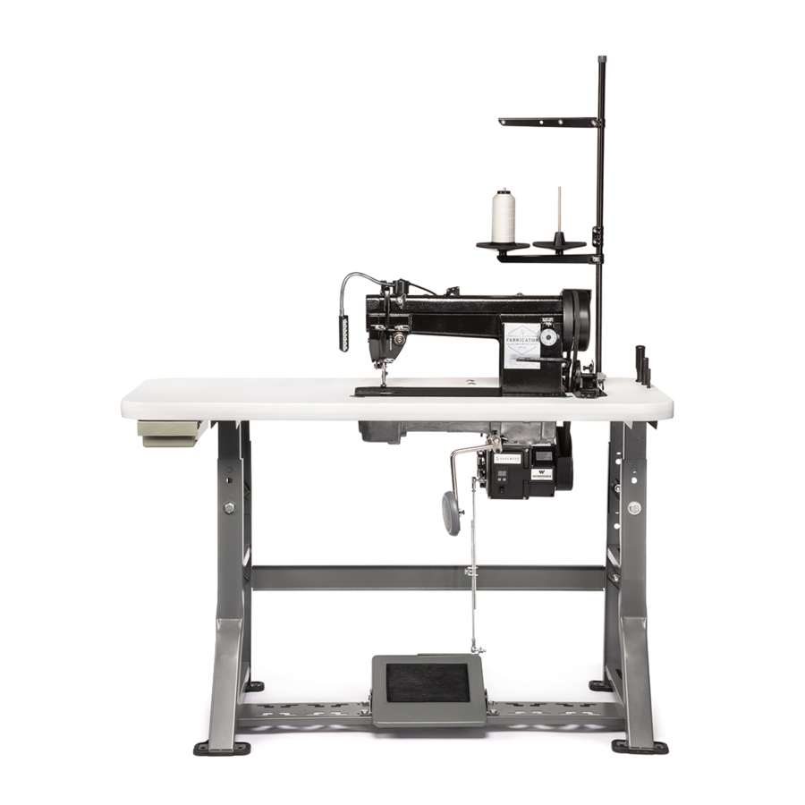
- Page 2 Welcome to Your Fabricator Sewing Machine! The Fabricator is a production machine that can sew all day with its best-in-class power system. Add in its slow speed power and control, which allows you to truly sew stitch-by-stitch, and you’ve got yourself a new trusty sidekick for all your canvas and upholstery projects.
-
Page 3: Table Of Contents
Table Of Contents Sewing Machine Safety Sewing with the Sailrite Fabricator ..........Starting to Sew ............Sailrite Fabricator Set-Up .......... Setting the Stitch Length & Power Stand Assembly ..........Operating in Reverse ..........Installing the Drawer ........... Adjusting the Pressure of the Presser Feet .... -
Page 4: Sewing Machine Safety
SEWING MACHINE SAFETY Please observe the following when using your Sailrite sewing machine • Do not operate in conditions where you or the • Always use the proper voltage required for machine are or may become wet. the motor and light. -
Page 5: Sailrite Fabricator Set-Up
SAILRITE FABRICATOR SET-UP Our expert Sailrite technicians have checked and adjusted every component of this machine. It has been sewn off and all accessories have been prepared for easy installation. With this guidebook, you should be able to maintain and adjust your own machine. Please do not make substantial adjustments to machine settings unless in consultation with Sailrite. -
Page 6: Power Stand Assembly
H. Flip the legs upside-down and place the treadle mount bar (I) at the back of the forward most slots (Figure 3). Bolt the treadle mount bar to the bottom surface of each crossbar of the k-legs (Figure FRONT Sailrite.com... - Page 7 1/2" into the tabletop. Do not drill completely through. 5. Bolt the frame to the bottom of the tabletop using the enclosed hex head lag screws (J), locking washer (L) and washer (M) to lock at each position (Figure Sailrite Fabricator Guidebook...
-
Page 8: Installing The Drawer
Secure the rails to the underside of the table with the included screws 10). (K) on page 4 (Figure Tip: Do not over tighten the screws or they will prevent the drawer from sliding freely. FRONT Sailrite.com... -
Page 9: Installing Rubber Foot Pads
12). Be sure to adjust the height place (Figure before placing the sewing machine casting in the tabletop. Be sure all nuts and bolts are tight. Sailrite Fabricator Guidebook... -
Page 10: Installing The Treadle
Flip the table upright and check to make sure the treadle moves freely after the bolts are tightened. BEFORE CONTINUING: See “Attaching a Pulley” and “Installing the Workhorse Servo Motor” in the Workhorse Servo Motor Instructions. Sailrite.com... -
Page 11: Installing The Linkage Bar
Workhorse and 16). the L-bracket (Figure By increasing or decreasing the overlap of the linkage bar, different treadle pedal angles can be achieved. Use a size 14mm wrench to set 17). the angle to your preference (Figure Sailrite Fabricator Guidebook... -
Page 12: Oil Pan And Machine Installation
The edge of the oil tray with the crescent cutout should be facing the left side of the table, away from the belt slot. 19). (Figure Sailrite.com... - Page 13 (J). With help, lift and lower the sewing machine into the tabletop so that the chrome hinges fit into 22). the rubber pads (Figure Sailrite Fabricator Guidebook | 10...
-
Page 14: Check Motor Rotation
Plug in the motor, switch the power on and press down on the foot treadle to confirm operation now. If motor rotation is not counterclockwise, please refer to “Changing Motor Rotation” in the Workhorse Installation Instructions. 11 | Sailrite.com... -
Page 15: Securing The Stitch Pro Balance Wheel
Push the Posi-Pin (D) through the holes to lock the balance wheel to the bushing (it will spring back slightly). Rotation of the balance wheel will now cause the machine to function 26). (Figure Sailrite Fabricator Guidebook | 12... -
Page 16: Belt Adjustment For The Workhorse Servo Motor
Once the motor is in the correct position and all bolts are tightened, remove the belt so the pulley bracket can be installed. BEFORE CONTINUING: See “Installing the Pulley Cover” in the Workhorse instructions. 13 | Sailrite.com... -
Page 17: Attaching The Balance Wheel Belt Cover
31). Position the screw in the slot cover (Figure to provide proper belt clearance (typically all the way to the right end of the slot) (E). Sailrite Fabricator Guidebook | 14... -
Page 18: Attaching The Bobbin Winder
Pressing the thumb pad (B) will move the wheel into the belt in order to wind bobbins. The thumb pad is on a hinged bracket so that when thread has filled the bobbin, the mechanism will disengage the wheel from the belt. 15 | Sailrite.com... -
Page 19: Mounting The Led Light
To attach the light to the front face of the machine (C), use the adhesive pad included with the Flex20 light. Mounting the Thread Stand: Assemble the thread stand as shown 36). Secure it to the tabletop with (Figure included hardware. Sailrite Fabricator Guidebook | 16... -
Page 20: Installing The Knee Lift Assembly
Loosen the nut and push the knee lift lever until just before it engages the foot. Leave about one inch of play then tighten the set screw until it touches the oil tray. Tighten the nut to hold its location. 17 | Sailrite.com... -
Page 21: Check The Machine For Operation
Use your heel to push the bottom of the pedal and the machine will stop. Turn the motor off. See “Operation” in the Workhorse guidebook for more information and how to set the motor speed. | 18 Sailrite Fabricator Guidebook... -
Page 22: Auto Lubrication
When it becomes necessary to change the oil, unscrew plug (A), wipe the dirty oil and the dust from the oil drip pan, replace the plug and add fresh oil. Use any high quality, clear sewing machine oil. Highest Lowest 19 | Sailrite.com... - Page 23 The range of adjustment is about five turns (Figure 41). Note: If oil is splashing up through the needle plate when sewing, decrease the oil flow to the hook by turning the screw (E) counterclockwise. Sailrite Fabricator Guidebook | 20...
-
Page 24: Manual Oiling
42-43). slide (Figure Note: Once oiled, sew a scrap piece of material to make sure all excess oil is worked out of the machine so it does not leak onto your next project. 21 | Sailrite.com... - Page 25 | 22 Sailrite Fabricator Guidebook...
- Page 26 23 | Sailrite.com...
- Page 27 Using the Fabricator Now that your machine is all set up, it’s time to start sewing! This next section will explain setting up the machine to sew including how to wind bobbins, thread the machine and adjust the tension. | 24...
-
Page 28: Coordinating The Needle, Thread And Material
COORDINATING THE NEEDLE, THREAD AND MATERIAL The Sailrite Fabricator uses system 135 x 17 and 135 x 16 needles. Needle size depends on thread size and the fabric weight. Sewing heavy material with a small needle may result in needle breakage, skipped stitches or thread breaks, and too large of a needle may produce large holes that make tension adjustment sensitive and seams may leak. -
Page 29: Thread Recommendations
This chart offers needle and thread size recommendations for sewing standard, woven fabrics. Needle and thread recommendations for sewing specialty fabrics are available online in our Thread & Needle Recommendation Guide, downloadable from every fabric detail page. Sailrite Fabricator Guidebook | 26... -
Page 30: Preparing To Sew
48). The the thread cone as shown (Figure following steps will show you how to wind a bobbin, put the bobbin in the bobbin case and thread the machine. 27 | Sailrite.com... -
Page 31: How To Wind A Bobbin
(Figure 50). 3. Bring the thread forward to the bobbin and push the thread tail through one of the holes in the bobbin from the inside. Pull the tail out about 51). two inches (Figure Sailrite Fabricator Guidebook | 28... - Page 32 • Push the Posi-Pin gently into the hole in the balance wheel. • Rotate the balance wheel while lightly pushing on the Posi-Pin until you feel it connect with any of the 4 bushings holes. • Push the Pin all the way in and release. 29 | Sailrite.com...
-
Page 33: Bobbin Thread Winding Adjustment
(D) to control the fill. Rotate the screw clockwise to increase the amount of thread on the bobbin and counterclockwise to decrease the amount of thread. Note: The metal finger (E) can be bent by hand if more adjustment is required. Sailrite Fabricator Guidebook | 30... -
Page 34: Removing And Installing The Bobbin Case
The position of the bobbin case should be installed as shown, noting the directional position of lever (A) 58). (Figure Images taken with machine tilted back 31 | Sailrite.com... -
Page 35: How To Thread The Bobbin
(Figure 62). If it is not, take the bobbin out and flip it over. Now refer back to “Removing and Installing the Bobbin Case” page 31 to put the bobbin case back in the machine. Sailrite Fabricator Guidebook | 32... -
Page 36: Threading The Sewing Machine
(K) then (L) and then through the needle bar thread guide (M) from front to back. 11. Pass the thread from left to right through the eye of the needle (N) and draw the thread about 4 inches through the needle eye. 33 | Sailrite.com... - Page 37 | 34 Sailrite Fabricator Guidebook...
-
Page 38: Pulling Up The Bobbin Thread
(Figure 64). Use a small instrument (seam ripper, screwdriver, pencil etc.) to slide under the feet and pull both threads outward (Figure 65). The needle thread (A) should be through the inner presser foot when completed. 35 | Sailrite.com... -
Page 39: Sewing With The Sailrite Fabricator
SEWING WITH THE SAILRITE FABRICATOR Starting to Sew 1. Use the hand lever (C) or knee lift (page 17) to raise the presser feet. Then place the material to be sewn under the feet and use the hand lever/knee lift to lower it onto the material. -
Page 40: Setting The Stitch Length & Operating In Reverse
(B) is released. It is best to initiate reverse when the machine is in motion, but you may also manually rotate the balance wheel so the needle is either in its highest or lowest position before pressing the reverse lever and starting to sew. 37 | Sailrite.com... -
Page 41: Adjusting The Pressure Of The Presser Feet
To reduce pressure, loosen the two lock nuts (C) and turn the two pressure regulating thumb screws (D) counterclockwise as shown (Figure 69). After adjustment, tighten the lock nuts. The two screws should always be maintained at roughly the same height. Sailrite Fabricator Guidebook | 38... -
Page 42: Adjusting Upper Tension Assemblies
(C) is less than a 1/2 turn from maximum (turned snugly clockwise). If upper tension is tightened all the way down, raising the presser foot may bend the lever inside the machine that separates the disks, preventing the disks from opening correctly. 39 | Sailrite.com... -
Page 43: Adjusting Bobbin Thread Tension
Knots centered — Perfect Stitch tension to the point that the knots just disappear on the bottom side of the fabric. Knots visible on bottom: 1. Increase upper tension (G) 2. Decrease bobbin case tension (H) Sailrite Fabricator Guidebook | 40... -
Page 44: Removing Material From Under The Presser Feet
It may be necessary to increase pressure on the bobbin case spring when using light weight thread. The bobbin spring will not clamp down on the smaller diameter thread like it does on heavier thread. See page 39 & 40 for tension adjustment. 41 | Sailrite.com... -
Page 45: Fabricator Maintenance
This section explains in detail how to make the adjustments most often made by sewing machine mechanics on industrial machines. This knowledge empowers you to be able to maintain the Fabricator yourself. | 42 Sailrite Fabricator Guidebook... -
Page 46: Feed Dog Height Adjustment
Above Front lowest screw (B) shaft. Use this mark to determine the desired tilt 74). of the feed dog (Figure Below Front highest screw (B) Note: These drawings are exaggerated. Feed dog tilt is far less noticeable 43 | Sailrite.com... -
Page 47: Setting The Feed Dog Position
For example, if a change is made on page 45, changes outlined on pages 46-49 must be done to maintain proper timing. Sailrite Fabricator Guidebook | 44... -
Page 48: Adjusting Needle Position & Clearance Between Presser Feet
(Figure properly. Make a full rotation of the balance wheel and confirm the inner and outer presser feet still don’t touch (Figure 77). If adjustment is made, please refer to the “Note About Adjustments” on page 44. 45 | Sailrite.com... -
Page 49: Timing Between The Needle & The Rotating Hook
Timing Between the Needle & the Rotating Hook When timing the Sailrite Fabricator, it is important that the needle bar height is correct. Anytime the needle bar height is changed, it is critical that the timing be checked and, if necessary, reset to ensure the proper operation of your machine. - Page 50 (Figure 3. Ensure that the stitch length indicator is set to its lowest setting by pressing the “PUSH” tab and rotating the knob clockwise toward the 1mm stitch length (Figure 85). FEED DOG SCREWS NEEDLE PLATE SCREWS 47 | Sailrite.com...
- Page 51 86). 2.5mm location (Figure Rotate the balance wheel until the mark lines up with the machine casting (Figure 87). MARK Sailrite Fabricator Guidebook | 48...
- Page 52 Note: Loosen the most convenient screw to access last when in the step 6 position. This one screw can be adjusted alone as timing is fine tuned. Be certain to tighten all three screws when the timing is perfect. 49 | Sailrite.com...
-
Page 53: Adjusting The Presser Foot Lift
After loosening the screw, grab the outer presser foot and manually move it up or down as desired (set between 2mm and 4mm above the needle plate). Tighten the screw when done. Sailrite Fabricator Guidebook | 50... -
Page 54: Adjusting The Vertical Lift Of The Outer Presser Foot
Adjusting the Vertical Lift of the Outer Presser Foot Sailrite sets the outer presser foot at the maximum height. DO NOT further increase foot height or the machine will jam during operation. The amount of lift of the outer presser foot is increased or decreased with pivot slide (A). -
Page 55: Adjusting Feed Timing Of The Needle Bar, Presser Foot And Feed Dog
In this case, enlarge distance (D) as explained above but slide the nut down. Make adjustments until the needle arrives at (B) (the center of the feed dog hole at the end of the rotation). Sailrite Fabricator Guidebook | 52... -
Page 56: Stitch Length Adjustment Between
The flat on the link pin shaft should face screw (A). Retighten all screws. Note: Do not rotate the balance wheel while disassembled as it will disrupt the timing of the machine. 53 | Sailrite.com... -
Page 57: Adjusting The Thread Take-Up Spring
To adjust the travel of the thread take-up spring: Loosen set screw (I) and turn the complete tension assembly clockwise to increase the spring range (up to 1/2") or turn it counterclockwise to decrease the spring range 99). (down to 7/32") (Figure | 54 Sailrite Fabricator Guidebook... - Page 58 When done, the core should be reset to the same depth. To set spring tension as it was originally set by Sailrite: Loosen set screw (A) first and then turn the tension stud (B) counterclockwise to reduce the tension of thread take-up spring (D) to zero.
-
Page 59: Troubleshooting Skipped Stitches
See “To set the machine’s timing” on Also, make sure that the needle is in correctly page (page 25), and check the upper thread path (page 33). The thread should pass from left to right through the needle eye. Sailrite Fabricator Guidebook | 56... -
Page 60: Lack Of Stitch Tension
(A) position as shown (Figure 101). Material Thread Guide Position Light (less tension) Medium Heavy (more tension) 57 | Sailrite.com... -
Page 61: Schematics
Fabricator Schematics Understand the ins and outs of the Fabricator with complete parts and systems schematics. | 58 Sailrite Fabricator Guidebook... - Page 62 59 | Sailrite.com...
- Page 63 Screw for Small Tension Assembly ...22T1-011 Washer for Back Cover ......22T1-007 Large Thread Tension Assembly ....103297 Thread Guide ..........35T4-405 Set Screw ..........22T1-013 Thread Take Up Spring for Fabricator....20129 Elongated Thread Finger ......22T1-014 Belt Cover Small Screw Washer ... GB/T86 M4 GB/T86 M3 Rubber Plug (8.8) ........22T1-015...
- Page 64 61 | Sailrite.com...
- Page 65 Needle 135 x 17 (22) .........153 36T3-003D1 Feed Dog Lift Cam ....... Needle Screw ..........103012 36T3-003D2 Screw for Cam ........Posi-Pin Wheel Bushing for Fabricator ..120624 36T5-008E1 Separating Cam Piece ......36T3-004 Feed Cam ..........Front Feed Link ........22T3-09D1C Rear Feed Link ........4WF2-009A Vertical Shaft .........
- Page 66 63 | Sailrite.com...
- Page 67 ........End Screw for Lower Shaft ....22T4-001A1a1 Oil Wick ..........22T6--008D3 5WF4-002 Plug for End Screw ......22T4-001A1a2 Feed Shaft Front Crank ......Screw for Link ........36T5-008E3 Oil Seal for Front Lower Shaft ....22T4-003 Sailrite Fabricator Guidebook | 64...
- Page 68 65 | Sailrite.com...
- Page 69 Right Set Pin ..........5WFI-001 Stitch Dial Wheel ........ 36T5-007D2 22T6-008D3 Screw for Crank ........4WF2-004A Stitch Dial Face ........36T5-011 Stitch Length Push Lever ......36T5-010 36T5-007D4 Spring for Stitch Dial ........ Bushing for Stitch Dial ......Sailrite Fabricator Guidebook | 66...
- Page 70 67 | Sailrite.com...
- Page 71 .......... Knee Lift Lever ........22T7-007C2 61-04-01/B316 Screw for Outer Presser Foot ..35T3-304 Spring for Knee Lift Lever .......4WF3-001 Outer Presser Foot ........1KT4-006 Lock Screw for Bushing/Cam ..61-04-01/B308 Knee Lift Connecting Rod ....... Sailrite Fabricator Guidebook | 68...
- Page 72 69 | Sailrite.com...
- Page 73 Front Bushing for Upper/Lower Needle Motion 34T5-536a Connecting Pin for Feed Shaft Front Crank..5WF4-001 34T5-537 Upper Needle Motion Shaft ........Feed Shaft Front Crank ........5WF4-002 34T5-522 34T5-513a Screw for Needle Motion Components ....Screw for Needle Bar Motion Fork Lever..... Sailrite Fabricator Guidebook | 70...
- Page 74 71 | Sailrite.com...
- Page 75 Shaft for Large Oil Pump Gear ..... Screw for Oil Pump Cover ....GB/T68 M3X10 Oil Filter ..........22T8-008A Screw for Oil Pump ........22T8-009 Screw for Oil Tube Felt Clamp ....20T4-006 Lower Oil Pipe ........4WF4-005 Sailrite Fabricator Guidebook | 72...
- Page 76 73 | Sailrite.com...
- Page 77 Screw for Oil Tray Drain ...... 22T9-001A2 Stop Ring for Knee Lift Hinge Pin ..... GB896 9 Washer Oil Tray Drain Screw ....22T9-001A3 Belt Cover for Professional & Fabricator ..120616 Gasket for Oil Tray ........2KT9-008 Bobbin Winder ..........103276 Hinge Shaft for Knee Lift .....
-
Page 78: Machine Specifications
UNDERARM SPACE 10.25" X 5" BUILT-IN KNEE LIFT The sewing machine casting does not have an internal motor. It is powered by Sailrite’s exclusive Workhorse Servo motor using Sailrite’s patented Posi-Pin system (Pat. #7438009) and Stitch PRO Balance Wheel. 75 |... -
Page 79: Warranty
2-Year Limited Warranty ALL PARTS & LABOR ARE FULLY GUARANTEED FOR 2 YEARS BY SAILRITE. We are proud to provide you with everything you need to successfully maintain and repair your Fabricator Sewing Machine. Should you choose to return your machine for repairs, you will be responsible for delivery both ways. - Page 80 Equipping you to sew at home & on the water. 120652*1 Copyright ©2017 Sailrite Fabricator Guidebook Fabricator Patented Technology: #7438009...
Need help?
Do you have a question about the Fabricator and is the answer not in the manual?
Questions and answers
I just assembled my new Fabricator. The “PUSH” button lettering is worn off, and I cannot get the stitch length to change. First, why will it not change stitch length? I followed the directions in the manual. Second, this makes me feel that my machine was a returning along with a chip on the wheel and the pin pops out.
The stitch length may not be changing on the Sailrite Fabricator due to the following reasons:
1. Dial Stops Are Bypassed: If the PIP at the bottom of the plate is pushed away from the inside of the dial, the stops on the dial can be bypassed, preventing proper stitch length adjustment.
2. Improper Dial Operation: If the stitch length dial is turned too far or not operated correctly, it may not adjust the stitch length as expected.
3. Timing Issues: If the machine has gone out of time, skipped stitches or incorrect stitch formation may occur, which could give the impression that the stitch length is not changing.
4. Needle Bar Height: If the needle bar height is incorrect, the machine may not form stitches properly, affecting stitch length.
To resolve the issue, ensure the stitch length dial is operated correctly, check that the stops are engaged, and verify the machine’s timing and needle bar height.
This answer is automatically generated
Bobbin case will not remove, stuck