
Related Manuals for Allied Telesis XS900MX Series


Summary of Contents for Allied Telesis XS900MX Series
- Page 1 XS900MX Series Stackable 10Gigabit Ethernet Switches AlliedWare Plus™ Version 5.4.8 AT-XS916MXT AT-XS916MXS Installation Guide for VCStack ™ 613-002256 Rev. C...
- Page 2 Allied Telesis, Inc. has been advised of, known, or should have known, the...
- Page 3 Electrical Safety and Emissions Standards This section contains the following: “US Federal Communications Commission” “Industry Canada” “Emissions, Immunity and Electrical Safety Standards” on page 4 “Translated Safety Statements” on page 4 US Federal Communications Commission Radiated Energy Note This equipment has been tested and found to comply with the limits for a Class A digital device pursuant to Part 15 of FCC Rules.
- Page 4 Emissions, Immunity and Electrical Safety Standards RFI Emissions FCC Class A, EN55022 Class A, EN61000-3-2, EN61000-3-3, VCCI Class A, Warning In a domestic environment this product may cause radio interference in which case the user may be required to take adequate measures. ...
-
Page 5: Table Of Contents
Contents Preface ....................................13 Document Conventions ...............................14 Contacting Allied Telesis ..............................15 Chapter 1: Overview ................................ 17 Front Panels ..................................18 Features ....................................19 XS900MX Models .................................19 100Mbps and 1/10Gbps Twisted Pair Ports ...............................19 SFP/SFP+ Ports ................................19 LEDs .....................................19 Installation Options ...............................20 MAC Address Table..............................20 Management Software and Interfaces..........................20... - Page 6 Contents Chapter 3: Beginning the Installation ..........................47 Reviewing Safety Precautions ............................48 Choosing a Site for the Switch............................52 Unpacking the Switch ................................. 53 Installing the Power Cord Retaining Clip ..........................54 Chapter 4: Installing the Switch on a Table or in an Equipment Rack ............... 55 Installing the Switch on a Table or Desktop........................
- Page 7 XS900MX Series Installation Guide for VCStack What to Do Next .................................124 Cabling the Trunk Ports ..............................126 Powering on the Stack...............................127 Verifying the Stack................................129 Chapter 9: Cabling the Networking Ports ........................131 Cabling Twisted Pair Ports ..............................132 Installing SFP/SFP+ Transceivers.............................133 Installing AT-StackXS/1.0, AT-SP10TW1, or AT-SP10TW3 Cables .................136 Chapter 10: Troubleshooting ............................
- Page 8 Contents...
- Page 9 Figures Figure 1: AT-XS916MXT Switch Front Panel ........................18 Figure 2: AT-XS916MXS Switch Front Panel ........................18 Figure 3: Management Panel ...............................21 Figure 4: Stacking Transceiver .............................24 Figure 5: Link/activity LEDs for the Twisted Pair Ports......................26 Figure 6: Link/activity LEDs for the SFP/SFP+ Ports ......................27 Figure 7: Switch ID LED ...............................28 Figure 8: Switch ID LED Not in Low Power Mode ........................28 Figure 9: Switch ID LEDs in Low Power Mode ........................29...
- Page 10 Figures Figure 50: User Exec Mode Prompt............................87 Figure 51: SHOW VERSION Command..........................88 Figure 52: Moving to the Privileged Exec Mode with the ENABLE Command ..............89 Figure 53: Moving to the Global Configuration Mode with the CONFIGURE TERMINAL Command........89 Figure 54: Activating VCStack with the STACK ENABLE Command ...................89 Figure 55: Returning to the Privileged Exec Mode with the EXIT Command ...............89 Figure 56: Saving the Change with the WRITE Command....................90 Figure 57: Rebooting the Switch with the REBOOT Command....................90...
- Page 11 Tables Table 1: Link/activity LEDs for the Twisted Pair Ports ......................26 Table 2: Link/activity LEDs for the SFP/SFP+ Ports ......................27 Table 3: PORT Parameter Format ............................33 Table 4: Stacking Worksheet ...............................45 Table 5: Stacking Worksheet Columns ..........................45 Table 6: Configuring the Master Switch - Part I .........................111 Table 7: Configuring the Master Switch - Part II ........................113 Table 8: Verifying the Master Switch ..........................115 Table 9: Configuring the Member Switch - Part I .......................119...
- Page 12 Tables...
-
Page 13: Preface
Preface This guide contains the installation instructions for the XS900MX Series of Layer 3 10 Gigabit Ethernet switches. This preface contains the following sections: “Document Conventions” on page 14 “Contacting Allied Telesis” on page 15 Note This guide explains how to install two XS900MX Switches in a stack ™... -
Page 14: Document Conventions
Preface Document Conventions This document uses the following conventions: Note Notes provide additional information. Caution Cautions inform you that performing or omitting a specific action may result in equipment damage or loss of data. Warning Warnings inform you that performing or omitting a specific action may result in bodily injury. -
Page 15: Contacting Allied Telesis
XS900MX Series Installation Guide for VCStack Contacting Allied Telesis If you need assistance with this product, you may contact Allied Telesis technical support by going to the Support & Services section of the Allied Telesis web site at www.alliedtelesis.com/support. You can find links for the following services on this page: ... - Page 16 Preface...
-
Page 17: Chapter 1: Overview
Chapter 1 Overview This chapter contains the following sections: “Front Panels” on page 18 “Features” on page 19 “Management Panel” on page 21 “100Mbps and 1/10Gbps Twisted Pair Ports” on page 22 “1Gbps SFP and 10Gbps SFP+ Ports” on page 23 ... -
Page 18: Front Panels
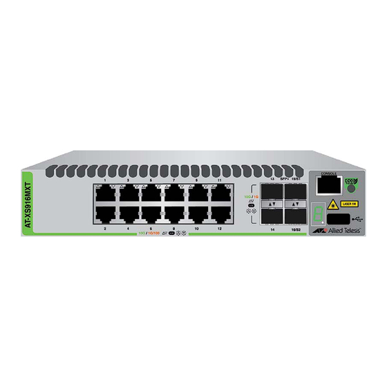
Chapter 1: Overview Front Panels The front panel of the AT-XS916MXT Switch is shown in Figure 1. 100Mbps and 1/10Gbps Twisted Pair Ports 1Gbps SFP and 10Gbps SFP+ Ports Default Trunk Ports Management Panel Figure 1. AT-XS916MXT Switch Front Panel The front panel of the AT-XS916MXS Switch is shown in Figure 2. -
Page 19: Features
XS900MX Series Installation Guide for VCStack Features The XS900MX Switches and their features are listed in this section: XS900MX Here are the model names: Models AT-XS916MXT AT-XS916MXS 100Mbps and Here are the basic features of the 100Mbps and 1/10Gbps twisted pair... -
Page 20: Installation Options
Chapter 1: Overview Installation Here are the installation options for the switches: Options Desk or tabletop 19-inch equipment rack Wall MAC Address Here are the basic features of the MAC address tables of the switches: Table Storage capacity of 16,000 dynamic MAC address entries ... -
Page 21: Management Panel
XS900MX Series Installation Guide for VCStack Management Panel Figure 3 identifies the components in the management panels on the XS900MX Series switches. Console Management Port eco-friendly button Switch ID LED USB Port Figure 3. Management Panel... -
Page 22: 100Mbps And 1/10Gbps Twisted Pair Ports
Chapter 1: Overview 100Mbps and 1/10Gbps Twisted Pair Ports The AT-XS916MXT and AT-XS916MXS Switches have twelve and four 100/1000/10GBASE-T ports, respectively. Speed The ports can operate at 100Mbps, 1Gbps, or 10Gbps. The speeds can be set manually using the management software or automatically with Auto-Negotiation (IEEE 802.3u), the default setting. -
Page 23: 1Gbps Sfp And 10Gbps Sfp+ Ports
XS900MX Series Installation Guide for VCStack 1Gbps SFP and 10Gbps SFP+ Ports The XS916MX Switches have ports for 1Gbps SFP or 10Gbps SFP+ transceivers.The AT-XS916MXT Switch has four ports and the AT-XS916MXS Switch has twelve ports. Transceivers are used to connect... -
Page 24: 15/S1 And 16/S2 Default Trunk Ports
Chapter 1: Overview 15/S1 and 16/S2 Default Trunk Ports The 15/S1 and 16/S2 ports can be used as regular networking ports or as trunk ports for a stack of two switches, with the VCStack feature. The switches of a VCStack function as a single virtual unit. They synchronize their actions so that switching operations, like spanning tree protocols, virtual LANs, and static port trunks, span across all the units and ports. -
Page 25: Eco-Friendly Button
XS900MX Series Installation Guide for VCStack eco-friendly Button The eco-friendly button on the front panel of the switch is used to toggle the port LEDs on or off. You might turn off the LEDs to conserve electricity when you are not monitoring the device. You can also toggle the LEDs with the ECOFRIENDLY LED and NO ECOFRIENDLY LED commands in the Global Configuration mode of the command line interface. -
Page 26: Leds
Chapter 1: Overview LEDs This section describes the functions of the LEDs. LEDs for the Each twisted pair port has one status LED that displays link and activity information. Refer to Figure 5. Twisted Pair Ports Link/activity LED for the Link/activity LED for the Bottom Port Top Port... -
Page 27: Switch Id Led
XS900MX Series Installation Guide for VCStack Link/activity LED for the Link/activity LED for the Bottom Port Top Port Figure 6. Link/activity LEDs for the SFP/SFP+ Ports The LEDs are described in Table 2. Table 2. Link/activity LEDs for the SFP/SFP+ Ports... -
Page 28: Figure 7: Switch Id Led
Chapter 1: Overview Switch ID LED Figure 7. Switch ID LED The states of the LED when the switch is not operating in the low power mode are shown in Figure 8. The switch is booting up. The switch has encountered a fault condition. The switch is operating as a stand-alone unit. -
Page 29: Figure 9: Switch Id Leds In Low Power Mode
XS900MX Series Installation Guide for VCStack Note You can use the SHOW SYSTEM ENVIRONMENT command in the command line interface to identify the source of the problem. The states of the LED when the switch is operating in the low power mode are shown in Figure 9. -
Page 30: Usb Port
Chapter 1: Overview USB Port The management panel has a USB port for storing configuration files on flash drives, restoring configuration files to switches whose settings have been lost or corrupted, or configuring replacement units. You can also use the port and flash drives to update the management firmware on the switch. -
Page 31: Console Port
XS900MX Series Installation Guide for VCStack Console Port The Console port is used to conduct management sessions with the switch to configure its features and parameter settings. This type of management uses serial RS-232 and is commonly referred to as local or out-of-band management because it is not conducted over your network. -
Page 32: Power Supply
Chapter 1: Overview Power Supply The XS900MX series switches come with one AC power supply. The back panels have one AC connector. The power supply is not field-replaceable; refer to “Technical Specifications” on page 143 for the input voltage range. -
Page 33: Specifying Ports In The Command Line Interface
XS900MX Series Installation Guide for VCStack Specifying Ports in the Command Line Interface The PORT parameter in the command line interface in the management software is used to specify individual ports on the switch. Figure 10 shows its format. port1... - Page 34 Chapter 1: Overview...
-
Page 35: Chapter 2: Virtual Chassis Stacking
“Master and Member Switches” on page 43 “Stacking Worksheet” on page 45 Note For more information on the VCStack feature, refer to the Stacking Introduction and Stacking Commands chapters in the Software Reference for XS900MX Series Switches, AlliedWare Plus Operating System from www.alliedtelesis.com/support. -
Page 36: Overview
Chapter 2: Virtual Chassis Stacking Overview The Virtual Chassis Stack (VCStack) feature allows you to connect two XS900MX Series switches into virtual switch so that the devices function as a single networking unit. Brief descriptions of the benefits of VCStack are given here: ... -
Page 37: General Stacking Guidelines
XS900MX Series Installation Guide for VCStack General Stacking Guidelines Here are the general guidelines to planning a stack: A stack can have two XS900MX Switches. The two XS900MX Switches of a stack can be the same model or different models (i.e., AT-XS916MXT and AT-XS916MXS... -
Page 38: Stack Trunk
Only the approved cables listed above will work in ports 15/S1 and 16/S2 when the ports are functioning as trunk ports. The cables must be from Allied Telesis. Similar cables from other network equipment providers might result in unpredictable behavior. -
Page 39: Figure 11: Stacking Cable
XS900MX Series Installation Guide for VCStack Ports 15/S1 and 16/S2 function as regular network ports when VCStack is disabled or other ports as designated as the trunk ports. Note The XS900MX Switches do not support the AT-SP10TW7 Direct Attach Cable. -
Page 40: Sfp/Sfp+ Ports
Chapter 2: Virtual Chassis Stacking A stack can have both switch models. An example is shown in Figure 13. Figure 13. Trunk of Default Ports 15/S1 and 16/S2 with Both Switch Models SFP/SFP+ Ports You can use any two SFP/SFP+ ports as the trunk port, instead of the default trunk ports 15/S1 and 16/S2. -
Page 41: Trunk Of Twisted Pair Ports
XS900MX Series Installation Guide for VCStack Figure 14. Example Trunk of Two SFP/SFP+ Ports A stack with a trunk of SFP/SFP+ ports can have both models. The example in Figure 15 uses ports 13 and 14 for the trunk. Figure 15. Example Trunk of Two SFP/SFP+ Ports with Both Switch... -
Page 42: Figure 16: Example Trunk Of Twisted Pair Ports
Chapter 2: Virtual Chassis Stacking The cabling must crossover on the ports. For example, if ports 1 and 2 are the trunk, port 1 on one switch must crossover to port 2 on the second switch and port 2 must crossover to port 1. ... -
Page 43: Master And Member Switches
XS900MX Series Installation Guide for VCStack Master and Member Switches The stack has one master switch. The functions of the master switch include: Coordinating and monitoring stack operations. Verifying that the switches are using the same version of management software. -
Page 44: Id Numbers
Chapter 2: Virtual Chassis Stacking ID Numbers Each switch must be assigned a unique ID number. The ID number can be 1 or 2; the default is 1. The ID numbers are displayed on the ID LEDs on the front panels of the units. You can assign the ID number yourself or, if you plan to use the default ports 15/S1 and 16/S2 for the trunk, you can let the switches assign them automatically. -
Page 45: Stacking Worksheet
XS900MX Series Installation Guide for VCStack Stacking Worksheet Configuring and maintaining a stack will be easier if you use the worksheet in Table 4. Table 4. Stacking Worksheet Trunk Trunk Switch Model Switch Priority Version Ports Location Cables Number Master Member 1. - Page 46 If you are not going to use default ports 15/S1 and 16/S2 for the trunk and instead use non- default ports, Allied Telesis recommends setting each switch’s priority value to match its ID value. This is to insure that the switch you want to be the master unit will be selected for that role.
-
Page 47: Chapter 3: Beginning The Installation
Chapter 3 Beginning the Installation The chapter contains the following sections: “Reviewing Safety Precautions” on page 48 “Choosing a Site for the Switch” on page 52 “Unpacking the Switch” on page 53 “Installing the Power Cord Retaining Clip” on page 54... -
Page 48: Reviewing Safety Precautions
Chapter 3: Beginning the Installation Reviewing Safety Precautions Review the following safety precautions before beginning the installation procedure. Note Safety statements that have the symbol are translated into multiple languages in the Translated Safety Statements document at www.alliedtelesis.com/library. Note Les consignes de sécurité... - Page 49 XS900MX Series Installation Guide for VCStack Warning Power cord is used as a disconnection device. To de-energize equipment, disconnect the power cord. Warning Class I Equipment. This equipment must be earthed. The power plug must be connected to a properly wired earth ground socket outlet.
- Page 50 Use dedicated power circuits or power conditioners to supply reliable electrical power to the device. Caution The chassis may be heavy and awkward to lift. Allied Telesis recommends that you get assistance when mounting the chassis in an equipment rack. ...
- Page 51 XS900MX Series Installation Guide for VCStack Caution The unit does not contain serviceable components. Please return damaged units for servicing. Warning When you remove an SFP module from this product, the case temperature of the SFP may exceed 40° C (158° F). Exercise caution when handling with unprotected hands.
-
Page 52: Choosing A Site For The Switch
Chapter 3: Beginning the Installation Choosing a Site for the Switch Observe these requirements when planning the installation of the switch. If you plan to install the switch in an equipment rack, check to be sure that the rack is safely secured so that it will not tip over. Devices in a rack should be installed starting at the bottom, with the heavier devices near the bottom of the rack. -
Page 53: Unpacking The Switch
XS900MX Series Installation Guide for VCStack Unpacking the Switch The XS900MX Switches come with the components listed in Figure 18. Note If any item is missing or damaged, contact your Allied Telesis sales representative for assistance. AC power cord Management cable, with RJ-45... -
Page 54: Installing The Power Cord Retaining Clip
Chapter 3: Beginning the Installation Installing the Power Cord Retaining Clip The power cord retaining clip that comes with the switch protects the power cord from being accidentally unplugged from the unit. To install the power cord retaining clip, position the “u” part facing down, press in the sides, and insert the ends of the clip into the holes in the retaining bracket on the AC connector on the switch. -
Page 55: Chapter 4: Installing The Switch On A Table Or In An Equipment Rack
Chapter 4 Installing the Switch on a Table or in an Equipment Rack This chapter contains the instructions for installing the switch on a table or in an equipment rack. The procedures in this chapter are listed here: “Installing the Switch on a Table or Desktop” on page 56 ... -
Page 56: Installing The Switch On A Table Or Desktop
Chapter 4: Installing the Switch on a Table or in an Equipment Rack Installing the Switch on a Table or Desktop This section contains the procedure for installing the switch on a table. Note The rubber feet on the bottom of the chassis should be left on for table installation. -
Page 57: Overview To Installing The Switch In An Equipment Rack
XS900MX Series Installation Guide for VCStack Overview to Installing the Switch in an Equipment Rack You can install XS900MX Switches in a 19-inch equipment rack two ways. One way is with the AT-RKMT-J14 brackets that come with the switch. Refer to Figure 20. -
Page 58: Figure 22: At-Rkmt-J15 Bracket With Switches
Chapter 4: Installing the Switch on a Table or in an Equipment Rack The bracket lets you install two switches side-by-side. Refer to Figure 22. Figure 22. AT-RKMT-J15 Bracket with Switches Note The AT-RKMT-J15 Bracket is purchased separately. For installation instructions refer, to “Installing the Switch in an Equipment Rack with the AT-RKMT-J15 Bracket”... -
Page 59: Installing The Switch In An Equipment Rack With At-Rkmt-J14 Brackets
XS900MX Series Installation Guide for VCStack Installing the Switch in an Equipment Rack with AT-RKMT-J14 Brackets This section contains the procedure for installing XS900MX Switches in a standard 19-inch equipment rack, with the AT-RKMT-J14 Brackets included with the units. Required Items... -
Page 60: Figure 24: At-Rkmt-J14 Bracket Holes
Chapter 4: Installing the Switch on a Table or in an Equipment Rack The brackets also have two sets of four holes. Refer to Figure 24. Set 1 Set 2 Figure 24. AT-RKMT-J14 Bracket Holes You can use the different sets of holes on the switch and brackets to install the switch in the equipment rack in a variety of orientations. -
Page 61: Installing The Switch
Please review the information in “Choosing a Site for the Switch” on page 52 before installing the switch in an equipment rack. Caution The chassis may be heavy and awkward to lift. Allied Telesis recommends that you get assistance when mounting the chassis in an equipment rack. E28... -
Page 62: Figure 27: Attaching The Handles To The At-Rkmt-J14 Brackets
Chapter 4: Installing the Switch on a Table or in an Equipment Rack Figure 27. Attaching the Handles to the AT-RKMT-J14 Brackets 2. Place the switch on a level, secure surface. 3. Attach the two brackets to the sides of the switch in the selected position, using the eight M4x6mm screws included with the unit. -
Page 63: Figure 29: Installing The Switch In An Equipment Rack
XS900MX Series Installation Guide for VCStack 4. Have another person hold the switch at the desired location in the equipment rack while you secure it using four standard equipment rack screws (not provided). Refer to Figure 29. Figure 29. Installing the Switch in an Equipment Rack... -
Page 64: Installing The Switch In An Equipment Rack With The At-Rkmt-J15 Bracket
Chapter 4: Installing the Switch on a Table or in an Equipment Rack Installing the Switch in an Equipment Rack with the AT-RKMT-J15 Bracket This section contains the procedure for installing XS900MX Switches in a standard 19-inch equipment rack, with the optional AT-RKMT-J15 Bracket. -
Page 65: Figure 31: Loosening The Two Thumbscrews On The Front Of The At-Rkmt-J15 Bracket
XS900MX Series Installation Guide for VCStack 2. Loosen the two thumbscrews on the front of the bracket. Refer to Figure 31. Figure 31. Loosening the Two Thumbscrews on the Front of the AT- RKMT-J15 Bracket 3. Slide out the bracket tray. Refer to Figure 32. -
Page 66: Figure 33: Turning The Switch Upside Down
Chapter 4: Installing the Switch on a Table or in an Equipment Rack Note Steps 4 to 6 remove the plastic feet from the bottom of the switch. You must remove the plastic feet to install the switch in the AT- RKMT-J15 Bracket. -
Page 67: Figure 35: Placing A Switch In The At-Rkmt-J15 Bracket
XS900MX Series Installation Guide for VCStack Figure 35. Placing a Switch in the AT-RKMT-J15 Bracket 8. Install two M4x6mm screws included with the switch to secure the switch to the bracket. Refer to Figure 36. Figure 36. Securing the Switch to the AT-RKMT-J15 Bracket... -
Page 68: Figure 37: Sliding In The Bracket Tray
Chapter 4: Installing the Switch on a Table or in an Equipment Rack 10. Slide in the bracket tray. Refer to Figure 37. Figure 37. Sliding in the Bracket Tray 11. Tighten the two thumbscrews to secure the tray to the bracket. Refer to Figure 38. -
Page 69: Chapter 5: Installing The Switch On A Wall
Chapter 5 Installing the Switch on a Wall The procedures in this chapter are listed here: “Switch Orientations on a Wall” on page 70 “Installation Guidelines” on page 71 “Plywood Base for a Wall with Wooden Studs” on page 73 ... -
Page 70: Switch Orientations On A Wall
Chapter 5: Installing the Switch on a Wall Switch Orientations on a Wall You can install the switch on a wall with the front panel on the left or right, as shown in Figure 39. Do not install it with the front panel on the top or bottom. -
Page 71: Installation Guidelines
XS900MX Series Installation Guide for VCStack Installation Guidelines Here are the guidelines to installing the switch on a wall: You can install the switch on a wall with wooden studs or a concrete wall. If you are installing the switch on a wall with wooden studs, you should use a plywood base to support the switch. - Page 72 Chapter 5: Installing the Switch on a Wall Caution The supplied screws and anchors might not be appropriate for all walls. A qualified building contractor should determine the hardware requirements for your wall prior to installing the switch. E88...
-
Page 73: Plywood Base For A Wall With Wooden Studs
XS900MX Series Installation Guide for VCStack Plywood Base for a Wall with Wooden Studs If you are installing the switch on a wall that has wooden studs, Allied Telesis recommends using a plywood base for the device. (A plywood base is not required for a concrete wall.) Refer to Figure 40. -
Page 74: Figure 41: Steps To Installing The Switch With A Plywood Base
Chapter 5: Installing the Switch on a Wall The plywood base should be mounted to two studs in the wall. The recommended minimum dimensions of the plywood base for the switch are listed here: Width: 55.9 centimeters (22 inches) ... -
Page 75: Installing A Plywood Base
XS900MX Series Installation Guide for VCStack Installing a Plywood Base A plywood base is recommended when installing the switch on a wall that has wooden studs. Refer to “Plywood Base for a Wall with Wooden Studs” on page 73. Consult a qualified building contractor for installation instructions for the plywood base. -
Page 76: Installing The Switch On A Plywood Base
This procedure assumes that the plywood base for the switch is already installed on the wall. Please review “Reviewing Safety Precautions” on page 48 and “Choosing a Site for the Switch” on page 52 before performing this procedure. Allied Telesis recommends a minimum of two people for this procedure. Warning The device is heavy. -
Page 77: Figure 43: Securing The Switch To The Plywood Base
XS900MX Series Installation Guide for VCStack 3. After attaching the brackets, have another person hold the switch on the plywood base on the wall while you secure it with four screws (not included with the switch). Refer to Figure 43. -
Page 78: Installing The Switch On A Concrete Wall
Chapter 5: Installing the Switch on a Wall Installing the Switch on a Concrete Wall This section contains the instructions for installing the switch on a concrete wall. Please review the information in the following sections before performing the procedure: ... -
Page 79: Figure 44: Marking The Locations Of The Bracket Holes On A Concrete Wall
Prior to drilling, set the drill to hammer and rotation mode. The modes break up the concrete and clean out the hole. Allied Telesis recommends cleaning out the holes with a brush or compressed air. 6. Insert the four provided anchors into the holes. -
Page 80: Figure 45: Installing The Switch On A Concrete Wall
Chapter 5: Installing the Switch on a Wall Figure 45. Installing the Switch on a Concrete Wall 8. Go to Chapter 6, “What to Do First” on page 81. -
Page 81: Chapter 6: What To Do First
Chapter 6 What to Do First The procedures in this chapter are: “Introduction” on page 82 “Powering on a Switch” on page 83 “Verifying the Status of VCStack” on page 85 “Starting a Local Management Session” on page 86 ... -
Page 82: Introduction
Chapter 6: What to Do First Introduction There are a couple steps you should perform on both switches before you cable the trunk ports and build the stack: The first is verify that VCStack is enabled on the switches. In all likelihood, it already is because that is its default setting. -
Page 83: Powering On A Switch
XS900MX Series Installation Guide for VCStack Powering on a Switch To power on a switch, perform the following procedure: 1. If you have not installed the power cord retaining clip, go to “Installing the Power Cord Retaining Clip” on page 54. -
Page 84: Figure 48: Connecting The Power Cord To An Ac Power Source
Chapter 6: What to Do First Figure 48. Connecting the Power Cord to an AC Power Source Note The illustration shows a North American power cord. Your power cord may be different. Note Refer to “Power Specifications” on page 144 for the power specifications of the switches. -
Page 85: Verifying The Status Of Vcstack
XS900MX Series Installation Guide for VCStack Verifying the Status of VCStack The first step to building a stack is to verify that VCStack is enabled on the switches. If it is disabled, you will need to enable it with the instructions in this chapter. -
Page 86: Starting A Local Management Session
Chapter 6: What to Do First Starting a Local Management Session To start a local management session on the switch, perform the following procedure: 1. Connect the RJ-45 connector on the management cable to the Console port on the front panel of the switch, as shown in Figure 49. Figure 49. -
Page 87: Figure 50: User Exec Mode Prompt
Figure 50. User Exec Mode Prompt The User Exec mode is the first level in the command mode interface. For complete information on the modes and commands, refer to the Software Reference for XS900MX Series Switches, AlliedWare Plus Operating System from www.alliedtelesis.com/support. -
Page 88: Displaying The Alliedware Plus Version Number
Before building the stack, you should first determine whether the switches have the same version of the AlliedWare Plus management software. If they have different versions, Allied Telesis recommends upgrading both switches to the latest version. For instructions. refer to the Software Reference for XS900MX Series Switches, AlliedWare Plus Operating System. -
Page 89: Activating Vcstack
XS900MX Series Installation Guide for VCStack Activating VCStack If you determined in “Verifying the Status of VCStack” on page 85 that VCStack is disabled, perform the following procedure to enable it: 1. Start a local management session. Refer to “Starting a Local Management Session”... -
Page 90: Figure 56: Saving The Change With The Write Command
Chapter 6: What to Do First 6. Enter the WRITE command to save your change, as shown in Figure 56. awplus# write Building configuration ... [OK] awplus# Figure 56. Saving the Change with the WRITE Command If this is the initial management session of the switch, the switch automatically creates in flash memory a new configuration file called DEFAULT.CFG to store your configuration change. -
Page 91: Chapter 7: Stacking With The Default Trunk Ports
Chapter 7 Stacking with the Default Trunk Ports This chapter contains the following procedures: “Introduction” on page 92 “Cabling the Default 15/S1 and 16/S2 Trunk Ports” on page 93 “Powering On the Switches Individually” on page 94 ... -
Page 92: Introduction
Chapter 7: Stacking with the Default Trunk Ports Introduction This chapter explains how to initially power on a stack when the switches are using default ports 15/S1 and 16/S2 for the trunk. If the stack is using other trunk ports, refer to Chapter 8, “Stacking with Non-default Trunk Ports”... -
Page 93: Cabling The Default 15/S1 And 16/S2 Trunk Ports
XS900MX Series Installation Guide for VCStack Cabling the Default 15/S1 and 16/S2 Trunk Ports Before powering on the stack, you need to cable the default 15/S1 and 16/ S2 trunk ports. The ports support the following cables as trunk cables: ... -
Page 94: Powering On The Switches Individually
Chapter 7: Stacking with the Default Trunk Ports Powering On the Switches Individually This procedure explains how you can control the assignment of the ID numbers of the switches by powering on the units one at a time. The first switch is assigned ID number 1 and the second unit ID number 2. - Page 95 XS900MX Series Installation Guide for VCStack Note Refer to “Power Specifications” on page 144 for the power specifications of the switches. Warning Power cord is used as a disconnection device. To de-energize equipment, disconnect the power cord. Note Pluggable Equipment. The socket outlet shall be installed near the ...
-
Page 96: Powering On The Switches Simultaneously
Chapter 7: Stacking with the Default Trunk Ports Powering On the Switches Simultaneously If you want the switches of the stack to use their MAC addresses to automatically assign the ID numbers during the initial power-on sequence, and to select the master switch themselves, power them on simultaneously. - Page 97 XS900MX Series Installation Guide for VCStack Warning Power cord is used as a disconnection device. To de-energize equipment, disconnect the power cord. Note Pluggable Equipment. The socket outlet shall be installed near the equipment and shall be easily accessible.
-
Page 98: Verifying The Stack
Chapter 7: Stacking with the Default Trunk Ports Verifying the Stack To verify stack operations, perform the following procedure: 1. Start a local management session on either switch. Refer to “Starting a Local Management Session” on page 86. 2. From the User Exec mode, enter the SHOW STACK command: awplus>... -
Page 99: Setting The Priority Numbers
XS900MX Series Installation Guide for VCStack Setting the Priority Numbers This procedure is optional. It explains how to configure the priority settings of the switches. Changing the priority settings protects the stack configuration should you ever power on the stack with a new member switch that has a lower MAC address than an existing master or member switch. -
Page 100: Figure 60: Returning To The Privileged Exec Mode
Chapter 7: Stacking with the Default Trunk Ports awplus(config)# exit awplus# Figure 60. Returning to the Privileged Exec Mode 4. Enter the WRITE command to save your change in the configuration file. The switch displays the confirmation prompt in Figure 61. awplus# write Building configuration ... -
Page 101: Monitoring The Initialization Processes
XS900MX Series Installation Guide for VCStack Monitoring the Initialization Processes You may monitor the initialization sequence of the stack by connecting a terminal or computer that has a terminal emulator program to the Console port on any switch in the stack. You will see the messages in Figure 62 here to Figure 64 on page 103. -
Page 102: Figure 63: Switch Initialization Messages (Continued)
Chapter 7: Stacking with the Default Trunk Ports Starting base/portmapper... Received event syslog.done Starting base/reboot-stability... Checking system reboot stability... Starting base/cron... Starting base/apteryx... Starting base/appmond... Starting base/clockcheck... Starting hardware/openhpi... Starting hardware/timeout... Starting base/inet... Starting base/modules... Received event modules.done Received event board.inserted Received event apteryx.done Starting network/kermond... -
Page 103: Figure 64: Switch Initialization Messages (Continued)
XS900MX Series Installation Guide for VCStack Assigning Active workload to HA processes: hsl, nsm, authd, epsrd, lacpd, lldpd, loopprotd mstpd, rmond, sflowd, imi, imiproxyd 00:01:04 awplus VCS[904]: Duplicate stack member 1 detected for eccd:6dc1.1a60 and eccd:6dc1.19ff 00:01:04 awplus VCS[904]: Automatically renumbering stack member 1 (eccd:6dc1.1a60), selecting unused member-ID... - Page 104 Chapter 7: Stacking with the Default Trunk Ports...
-
Page 105: Chapter 8: Stacking With Non-Default Trunk Ports
Chapter 8 Stacking with Non-default Trunk Ports This chapter contains the following sections: “Introduction” on page 106 “Command Summary” on page 107 “Configuring the Master Switch” on page 110 “Configuring the Member Switch” on page 118 ... -
Page 106: Introduction
5. “Cabling the Trunk Ports” on page 126. 6. “Powering on the Stack” on page 127 7. “Verifying the Stack” on page 129 The procedures should be performed in the order above. Allied Telesis recommends reviewing “Command Summary” on page 107 before performing procedures 3 and 4. -
Page 107: Command Summary
XS900MX Series Installation Guide for VCStack Command Summary The following sections briefly describe the commands for configuring the master and member switches for stacking with non-default trunk ports. For further instructions, refer to the Software Reference for XS900MX Switch, AlliedWare Plus Operating System. After reviewing the commands, go to “Configuring the Master Switch”... -
Page 108: Stack Renumber
MAC address, the higher the priority. A switch can have only one priority number. Allied Telesis recommends settings a switch’s priority number to match its ID number. For example, the switch with ID 1 should be assigned priority 1 and switch with ID 2 should be assigned priority 2. -
Page 109: Switch Provision
XS900MX Series Installation Guide for VCStack SWITCH The master and member switches have to know about each other before you power on the stack for the first time. This involves using the SWITCH PROVISION PROVISION command to add the member switches as provisioned units to the master switch. -
Page 110: Configuring The Master Switch
Chapter 8: Stacking with Non-default Trunk Ports Configuring the Master Switch This section contains the following procedures for configuring the master switch of the stack: “General Steps for the Master Switch,” next “Configuring the Master Switch - Part I” on page 111 ... -
Page 111: Configuring The Master Switch - Part I
XS900MX Series Installation Guide for VCStack 6. Start a new local management session. 7. Verify the changes with the SHOW STACK and SHOW RUNNING- CONFIG command. Configuring the To configure the master switch for a stack trunk of ports other than the default trunk ports, perform the procedure in Table 6. - Page 112 Chapter 8: Stacking with Non-default Trunk Ports Table 6. Configuring the Master Switch - Part I (Continued) Step Description and Command Activate VCStack on the switch with the STACK ENABLE command. awplus(config)# stack enable % Automatically enabling ‘stack virtual-mac’ to minimize disruption form failovers.
-
Page 113: Configuring The Master Switch - Part Ii
XS900MX Series Installation Guide for VCStack Table 6. Configuring the Master Switch - Part I (Continued) Step Description and Command Steps 13 to 16 save your changes. Return to the Global Configuration mode with the EXIT command: awplus(config-if)# exit Return to the Privileged Exec mode. -
Page 114: Table 7: Configuring The Master Switch - Part Ii
Chapter 8: Stacking with Non-default Trunk Ports Table 7. Configuring the Master Switch - Part II (Continued) Step Description and Command Steps 3 and 4 remove the stacking function from the default trunk ports 15/S1 and 16/S2 on the provisioned member switch. Enter the port Interface modes of the default trunk ports 15/S1 and 16/S2 on the provisioned member switch: awplus(config)# interface port2.0.15-2.0.16... -
Page 115: Verifying The Master Switch
XS900MX Series Installation Guide for VCStack Table 7. Configuring the Master Switch - Part II (Continued) Step Description and Command Restart the switch with the REBOOT command. awplus# reboot reboot system? (y/n): awplus# Type “Y” for yes. Wait two minutes for the switch to initialize the management software. - Page 116 Chapter 8: Stacking with Non-default Trunk Ports Table 8. Verifying the Master Switch (Continued) Step Description and Command Enter the SHOW STACK command. Here is an example: awplus# show stack Virtual Chassis Stacking summary information ID Pending ID MAC address Priority Status Role...
-
Page 117: What To Do Next
XS900MX Series Installation Guide for VCStack What to Do Next After configuring the master switch, do the following: 1. Power off the switch by disconnecting its AC power cord from the AC power sources. Refer to Figure 65 on page 117. -
Page 118: Configuring The Member Switch
Chapter 8: Stacking with Non-default Trunk Ports Configuring the Member Switch Here are the procedures for configuring the member switch. “General Steps for the Member Switch” on page 118 “Configuring the Member Switch - Part I” on page 119 ... -
Page 119: Configuring The Member Switch - Part I
XS900MX Series Installation Guide for VCStack 4. Designate the new trunk ports on the member switch with the STACKPORT command in the port Interface mode. 5. Remove stacking from the default trunk ports 15/S1 and 16/S2 on the provisioned master switch with the NO STACKPORT command. - Page 120 Chapter 8: Stacking with Non-default Trunk Ports Table 9. Configuring the Member Switch - Part I (Continued) Step Description and Command Step 6 and 7 enable VCStack, if necessary. Examine the System ID LED on the front panel of the switch. If it is displaying “0”, VCStack is disabled.
-
Page 121: Configuring The Member Switch - Part Ii
XS900MX Series Installation Guide for VCStack Table 9. Configuring the Member Switch - Part I (Continued) Step Description and Command Step 14 verifies your changes. Check the ID LED on the front panel and do one of the following: - If the ID LED is displaying 2, go to “Configuring the Member Switch - Part II,” next. -
Page 122: Table 10: Configuring The Member Switch - Part Ii
Chapter 8: Stacking with Non-default Trunk Ports Table 10. Configuring the Member Switch - Part II (Continued) Step Description and Command Remove the ports from the trunk with the NO STACKPORT command: awplus(config-if)# no stackport % Save the config and restart the system for this change to take effect. -
Page 123: Verifying The Member Switch
XS900MX Series Installation Guide for VCStack Table 10. Configuring the Member Switch - Part II (Continued) Step Description and Command Designate the ports as the trunk with the STACKPORT command. awplus(config-if)# stackport % Save the config and restart the system for this change to take effect. -
Page 124: What To Do Next
Chapter 8: Stacking with Non-default Trunk Ports Table 11. Verifying the Member Switch (Continued) Step Description and Command Enter the SHOW STACK DETAIL command. Examine the display for Stack member 2: awplus# show stack detail Stack member 2: -------------------------------------------------------------- MAC address e01a:ea20:8011 Last role change Thur Nov 23 21:15:20 2018... - Page 125 XS900MX Series Installation Guide for VCStack Note When cabling the trunk ports, remember to crossover the cables. For example, if ports 1 and 2 are the trunk, port 1 on one switch has to connect to port 2 on the second switch.
-
Page 126: Cabling The Trunk Ports
Chapter 8: Stacking with Non-default Trunk Ports Cabling the Trunk Ports After configuring the master and member switches, cable the trunk ports. If you are using two SFP/SFP+ ports for the trunk, you have to use the following cables: AT-StackXS/1.0 (1 meter) stacking transceiver and cable ... -
Page 127: Powering On The Stack
XS900MX Series Installation Guide for VCStack Powering on the Stack Please verify the following before powering on the stack for the first time: If you are using SFP/SFP+ ports for the trunk, are you using approved stacking cables? Refer to “Default 15/S1 and 16/S2 Ports”... - Page 128 Chapter 8: Stacking with Non-default Trunk Ports Note Pluggable Equipment. The socket outlet shall be installed near the equipment and shall be easily accessible. E5 4. Wait three minutes for the switches to form the stack. 5. Go to “Verifying the Stack” on page 129.
-
Page 129: Verifying The Stack
XS900MX Series Installation Guide for VCStack Verifying the Stack To verify the stack, perform the following procedure: 1. Start a local management session on either the master or member switch. Refer to “Starting a Local Management Session” on page 86. - Page 130 Chapter 8: Stacking with Non-default Trunk Ports...
-
Page 131: Chapter 9: Cabling The Networking Ports
Chapter 9 Cabling the Networking Ports This chapter contains the following procedures: “Cabling Twisted Pair Ports” on page 132 “Installing SFP/SFP+ Transceivers” on page 133 “Installing AT-StackXS/1.0, AT-SP10TW1, or AT-SP10TW3 Cables” on page 136... -
Page 132: Cabling Twisted Pair Ports
Chapter 9: Cabling the Networking Ports Cabling Twisted Pair Ports Here are the guidelines to cabling the 100Mbps and 1/10Gbps twisted pair ports: The cable specifications for the twisted pair ports are listed in “Cable Requirements” on page 22. ... -
Page 133: Installing Sfp/Sfp+ Transceivers
XS900MX Series Installation Guide for VCStack Installing SFP/SFP+ Transceivers This section contains guidelines and the procedure for installing SFP/ SFP+ transceivers. Here are general installation guidelines for SFP/SFP+ transceivers: SFP/SFP+ transceivers are hot-swappable. You can install them while the chassis is powered on. -
Page 134: Figure 68: Installing An Sfp/Sfp+ Transceiver
Chapter 9: Cabling the Networking Ports 3. Position the transceiver. For a top slot, position the transceiver with the handle on top. For a bottom slot, position the transceiver with the handle beneath the module. 4. Slide the transceiver into the slot until it clicks into place. See Figure 68. -
Page 135: Figure 70: Positioning The Sfp Handle In The Upright Position
XS900MX Series Installation Guide for VCStack 6. Verify the position of the handle on the SFP transceiver. For a top slot, the handle is in the upright position. Refer to Figure 70. For a bottom slot, the handle should be in the down position. -
Page 136: Installing At-Stackxs/1.0, At-Sp10Tw1, Or At-Sp10Tw3 Cables
Figure 72. Removing the Dust Cover from the Transceiver 4. To install the transceiver in a port in the top row, position the transceiver with the Allied Telesis label facing up. To install the transceiver in a port in the bottom row, position the transceiver with the... -
Page 137: Figure 73: Installing At-Sp10Tw Cables
XS900MX Series Installation Guide for VCStack Figure 73. Installing AT-SP10TW Cables 5. Slide the transceiver into the port until it clicks into place. 6. Connect the other end of the cable into an SFP+ port on another network device. Note If you are using the cable as trunk cables for VCStack, remember that the cables must crossover to different ports. - Page 138 Chapter 9: Cabling the Networking Ports...
-
Page 139: Chapter 10: Troubleshooting
This chapter contains suggestions on how to troubleshoot the switch if a problem occurs. Note For further assistance, please contact Allied Telesis Technical Support at www.alliedtelesis.com/support. Problem 1: The Switch ID LED on the front of the switch is off. - Page 140 Chapter 10: Troubleshooting If you are using default trunk ports 15/S1 and 16/S2 ports or other SFP/ SFP+ ports as the trunk, try the following: If you are using SFP/SFP+ ports for the trunk, verify that you are using approved stacking transceivers. Refer to “Default 15/S1 and 16/S2 Ports”...
- Page 141 XS900MX Series Installation Guide for VCStack Check to be sure that the transceiver is not installed in port S1 or S2 in the switch. Those ports do not support SFP or SFP+ transceivers when VCStack is enabled. Verify that the operating specifications of the fiber optic ports on the transceiver and remote network device are compatible.
- Page 142 The input voltage on the power supply is outside the normal operating range. The internal temperature of the switch has exceeded the normal operating range, and the switch might shut down. Contact your Allied Telesis sales representative for assistance.
-
Page 143: Appendix A: Technical Specifications
Appendix A Technical Specifications This appendix contains the following sections: "Physical Specifications” "Environmental Specifications” on page 144 "Power Specifications” on page 144 "Certifications” on page 145 "RJ-45 Twisted Pair Port Pinouts” on page 146 "RJ-45 Style Serial Console Port Pinouts”... -
Page 144: Environmental Specifications
Appendix A: Technical Specifications Environmental Specifications Table 15. Environmental Specifications Operating Ambient Temperature 0° C to 50° C (32° F to 122° F) Storage Temperature -25° C to 70° C (-13° F to 158° F) Operating Humidity 5% to 90% noncondensing Storage Humidity 5% to 95% noncondensing Maximum Operating Altitude... -
Page 145: Certifications
XS900MX Series Installation Guide for VCStack Certifications Table 19. Product Certifications RFI Emissions FCC Class A, EN55022 Class A, EN61000-3-2, EN61000-3-3, VCCI Class A, RCM EMC (Immunity) EN55024 UL 60950-1 ( Electrical and Laser Safety CSA-C22 No. 60950-1 ( EN60950-1 (TUV),... -
Page 146: Rj-45 Twisted Pair Port Pinouts
Appendix A: Technical Specifications RJ-45 Twisted Pair Port Pinouts Figure 74 illustrates the pin layout of the RJ-45 connectors and ports. Figure 74. RJ-45 Socket Pin Layout (Front View) Table 20 lists the pin signals for 10 and 100 Mbps. Table 20. -
Page 147: Rj-45 Style Serial Console Port Pinouts
XS900MX Series Installation Guide for VCStack Table 21. Pin Signals for 1000 Mbps (Continued) Pinouts Pair Pair 3 - Pair 2 - Pair 4 + Pair 4 - RJ-45 Style Serial Console Port Pinouts The pin signals of the RJ-45 style serial Console port are listed in Table 22. - Page 148 Appendix A: Technical Specifications...
Need help?
Do you have a question about the XS900MX Series and is the answer not in the manual?
Questions and answers