
Related Manuals for Allied Telesis x240 Series


Summary of Contents for Allied Telesis x240 Series
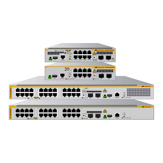
- Page 1 Series MULTI-GIGABIT LAYER 2 SWITCHES x240-10GHXm PoE++ x240-10GTXm x240-26GHXm PoE++ x240-26GTXm Installation Guide 613-003113 Rev. A...
- Page 2 Allied Telesis, Inc. has been advised of, known, or should have known, the...
-
Page 3: Electrical Safety And Emissions Standards
Electrical Safety and Emissions Standards This product meets the following standards. U.S. Federal Communications Commission Radiated Energy Note: This equipment has been tested and found to comply with the limits for a Class A digital device pursuant to Part 15 of FCC Rules. -
Page 4: Regulatory Approvals
Regulatory Approvals Compliance Marks CE, CULUS, UL-EU, RCM Electromagnetic Emissions FCC Part 15 Subpart B, Class A Information Technology Equipment for industrial environments ICES 003 Class A Information Technology Equipment (Including Digital Apparatus) - Limits and Methods of Measurement (Canadian Standard) EN 55032 Class A ... -
Page 5: Environmental Compliance
EN 62368-1 Audio/video, information and communication technology equipment - Part 1: Safety requirements; IEC 62368-1 Audio/video, information and communication technology equipment - Part 1: Safety requirements; EN (IEC) 60825-1 Safety of laser products Environmental Compliance Restriction of Hazardous Substances - RoHS Waste from Electrical and Electronic Equipment - WEEE Laser Safety EN (IEC) 60825-1... - Page 6 Translated Safety Statements Important: Safety statements with the symbol are translated into multiple languages in Translated Safety Statements at alliedtelesis.com/us/en/library/search. Übersetzte Sicherheitshinweise Wichtig: Sicherheitshinweise mit dem -Symbol werden in Translated Safety Statements bei alliedtelesis.com/us/en/library/search in mehrere Sprachen übersetzt. Declaraciones de seguridad traducidas Importante: Las declaraciones de seguridad con el símbolo ...
-
Page 7: Table Of Contents
Contents Preface: .....................................15 Document Conventions ..............................16 Contacting Allied Telesis ..............................17 Chapter 1: Overview ................................ 19 Front and Rear Panels ..............................20 x240-10GHXm Front Panel ...........................20 x240-10GTXm Front Panel ...........................20 x240-26GHXm Front Panel ...........................20 x240-26GTXm Front Panel ...........................21 x240-10GHXm Rear Panel ...........................21 x240-10GTXm Rear Panel ............................21... - Page 8 Contents Console Port ................................41 Power Supply and Fan ..............................43 Power Supply ............................... 43 Fan ..................................43 Chapter 2: Beginning the Installation ..........................45 Reviewing Safety Precautions ............................. 46 Choosing a Site for the Switch ............................ 50 Unpacking the x240-10GHXm or x240-10GTXm Switch..................... 51 Unpacking the x240-26GHXm or x240-26GTXm Switch.....................
- Page 9 Series Installation Guide Step 2: Configuring Node-01..........................114 Step 3: Configuring Node-02..........................115 Checking the Status of the Stack ..........................116 Running Commands on Devices in the Management Stack ..................117 Copying Files Between Management Stack Members....................118 Using Remote Login to Copy Files Between Other Units in the Management Stack..........118 Chapter 10: Troubleshooting ............................
- Page 10 Contents...
- Page 11 Figure 45: Attaching the Equipment Rack Brackets to the x240-26GHXm Switch...............76 Figure 46: Installing the x240-26GHXm Switch in an Equipment Rack................77 Figure 47: Positioning the x240 Series Switches on the Wall....................80 Figure 48: Attaching the Wall Brackets to the Switch ......................83...
- Page 12 Figures Figure 50: Securing the Switch to the Wall Using the Keyhole.....................85 Figure 51: Securing the Chassis Using the Keyhole......................86 Figure 52: Securing the Switch Using the Screw Holes......................86 Figure 53: Wall Mounting of Switch, Brackets, and Screws (Top View) ................87 Figure 54: Removing the Dust Plug from an SFP+ Port .......................93 Figure 55: Installing SFP+ Transceivers..........................93 Figure 56: Removing the Dust Cover from an SFP or SFP+ Transceiver ................94...
- Page 13 Table 8: Fault and Power LEDS ............................37 Table 9: USB Port LED ................................40 Table 10: Fan in the x240 Series Switches .........................43 Table 11: PORT Parameter Format ...........................110 Table 12: Fields in the Output of the ‘show mstack node’ Command ................116 Table 13: Product Dimensions (WxDxH) ...........................124...
- Page 14 Tables...
-
Page 15: Preface
Preface The x240 series devices are Layer 2 Multi-Gigabit Ethernet switches. This guide contains the installation instructions for the following products: x240-10GHXm x240-10GTXm x240-26GHXm x240-26GTXm This preface contains the following sections: “Document Conventions” on page 16 ... -
Page 16: Document Conventions
Preface Document Conventions This document uses the following conventions: Note Notes provide additional information. Caution Cautions inform you that performing or omitting a specific action may result in equipment damage or loss of data. Warning Warnings inform you that performing or omitting a specific action may result in bodily injury. -
Page 17: Contacting Allied Telesis
Series Installation Guide Contacting Allied Telesis If you need assistance with this product, visit the Allied Telesis web site at www.alliedtelesis.com/services. - Page 18 Preface...
-
Page 19: Chapter 1: Overview
Chapter 1 Overview This chapter contains the following sections: “Front and Rear Panels” on page 20 “Management Panel” on page 23 “Features” on page 24 “10M/100M/1G/2.5G/5G Copper Ports” on page 28 “Power Over Ethernet (PoE) on the x240-10GHXm and x240-26GHXm ... -
Page 20: Front And Rear Panels
Chapter 1: Overview Front and Rear Panels This section shows the front and rear panels of the x240 series switches. x240-10GHXm The front panel of x240-10GHXm switch with PoE++ is shown in Figure 1. Front Panel POE++ Management 1/10G SFP+ 10M/100M/1/2.5/5G... -
Page 21: X240-26Gtxm Front Panel
Series Installation Guide x240-26GTXm The front panel of the x240-26GTXm Switch is shown in Figure 4. Front Panel 1/10G SFP+Uplink Management 10M/100M/1/2.5/5G Ports 25-26 Panel Copper Ports 1-24 Figure 4. Front Panel of the x240-26GTXm Switch x240-10GHXm The rear panel of the x240-10GHXm Switch is shown in Figure 5. -
Page 22: Rear Panel Of X240-26Ghxm And X240-26Gtxm
Chapter 1: Overview Rear Panel of The rear panel of the x240-26GHXm and x240-26GTXm switches is shown in Figure 7. x240-26GHXm x240-26GTXm AC Power Supply Connector Figure 7. Rear Panel of the x240-26GHXm and x240-26GTXm Switches... -
Page 23: Management Panel
Series Installation Guide Management Panel Figure 8 identifies the components on the management panel. USB Port Console eco-friendly Management Button Port Figure 8. Management Panel... -
Page 24: Features
Copper Ports x240-10GHXm 240W x240-10GTXm x240-26GHXm 370W x240-26GTXm 10/100M/1/2.5/5G The copper ports on the x240 series switches have these features: Copper Ports Speeds of 10/100M/1/2.5/5G 100 meters (328 feet) maximum operating distance per port Full-duplex mode Auto-Negotiation for speed and duplex mode ... -
Page 25: 1/10G Sfp+ Ports
Series Installation Guide 1/10G SFP+ Ports The 1/10G SFP+ uplink ports support the following types of transceivers: Examples of SFP 1Gbps transceivers include: SPSX and LR short and long distance transceivers using multi-mode or single mode fiber optic cable. -
Page 26: Leds
Chapter 1: Overview Additional PoE capabilities include: Support powered device classes 0 to 8. Dynamic PoE power budget allocation, according to powered device consumptions and/or PoE port priorities. Uninterrupted PoE during warm switch restarts. LEDs Here are the port LEDs: The SFP transceiver ports have link/activity LEDs. -
Page 27: Usb Port
Series Installation Guide USB Port Here are the features and functions of the USB port: USB 2.0 compatible Store switch configuration files on flash drives Restore configuration files from flash drive to switches whose settings have been lost or corrupted, or to configure replacement... -
Page 28: 100M/1G/2.5G/5G Copper Ports
Chapter 1: Overview 10M/100M/1G/2.5G/5G Copper Ports The following sections describe the copper ports on the x240 series switches. Connector Type The copper ports have 8-pin RJ-45 connectors. The ports use four pins at 10/100Mbps and all eight pins at 1G/2.5G/5G. The pin assignments are listed in “RJ-45 Style Serial Console Port Pinouts”... -
Page 29: Automatic Mdix Detection
Series Installation Guide Automatic MDIX The copper ports are IEEE 802.3ab compliant. They feature automatic MDIX detection when operating at 10 or 100Mbps. (Automatic MDIX Detection detection does not apply to higher speeds.) The switch automatically configures the ports to MDI or MDI-X depending on the wiring configurations of the end nodes. -
Page 30: Table 2: Leds For Poe Ports On The X240-10Ghxm And X240-26Ghxm
Chapter 1: Overview Table 2. LEDs for PoE Ports on the x240-10GHXm and x240-26GHXm State Description Link/Activity LED (Left LED) Solid Green The port has established a link to a network device. Flashing Green The port is transmitting or receiving packets. Possible causes of this state are listed here: The port has not established a link with ... -
Page 31: X240-10Gtxm And X240-26Gtxm Leds
Series Installation Guide x240-10GTXm The non-PoE copper ports on the x240-10GTXm and x240-26GTXm switches have two LEDs. The LEDs are shown in Figure 10. x240-26GTXm Not Used Link/Activity LEDs Link/Activity Not Used Figure 10. LEDs for the Copper Ports on the x240-10GTXm and x240-26GTXm Switches The states of the port LEDs are described in Table 3 on page 31. -
Page 32: Power Over Ethernet (Poe) On The X240-10Ghxm And X240-26Ghxm Switches
Chapter 1: Overview Power Over Ethernet (PoE) on the x240-10GHXm and x240-26GHXm Switches The x240-10GHXm and x240-26GHXm Switches feature PoE++ on all 10M/100M/1G/2.5G/5G copper ports. With PoE++, the switch can supply DC power to network devices over the same copper cables that carry the network traffic. -
Page 33: Power Budget
Series Installation Guide Table 4. IEEE Powered Device Classes Maximum Power Class Output from a Switch PD Power Range Port 15.4W 0.44W to 12.95W 4.0W 0.44W to 3.84W 7.0W 3.84W to 6.49W 15.4W 6.49W to 12.95W 30.0W 12.95W to 25.5W 45.0W... -
Page 34: Port Priorities
Chapter 1: Overview Port Priorities If the switch determines that the power requirements of the powered devices exceed its power budget, it will deny power to some ports based on a system called port priorities. You can use this mechanism to ensure that powered devices critical to the operations of your network are given preferential treatment by the switch in the distribution of power should the demands of the devices exceed the available capacity. -
Page 35: Table 6: Poe Alternatives A And B For The Copper Ports
Series Installation Guide It takes four wires to deliver DC power to a powered device. With Alternative A, power is delivered on pins 1, 2, 3, and 6. These are the same pins in 10Base-T and 100Base-TX devices that carry the network data. -
Page 36: Sfp+ Transceiver Ports
The x240 series switches have two SFP+ transceiver ports. SFP+ SFP+ transceivers are purchased separately. For a list of supported transceivers, refer to the product data sheet on the Allied Telesis web site. Transceivers LEDs Each transceiver port has one LED. Refer to Figure 11. -
Page 37: Fault And Power Leds
Series Installation Guide Fault and Power LEDs The Fault and Power LEDs are shown in Figure 12. Fault and Power LEDs Figure 12. Fault and Power LEDs Note The USB LED is described in “USB Port” on page 40. - Page 38 Chapter 1: Overview Table 8. Fault and Power LEDS (Continued) State Description The switch is powered off or the input power is outside the normal operating range.
-
Page 39: Eco-Friendly Button
Series Installation Guide eco-friendly Button The eco-friendly button on the front panel of the switch is used to toggle the port LEDs on or off. See Figure 13. You can turn off the LEDs to conserve electricity when you are not using them to monitor the device. -
Page 40: Usb Port
Chapter 1: Overview USB Port You can use the USB port on the management panel for the following functions: Store configuration files on flash drives. Restore configuration files to switches whose settings have been lost or corrupted. Configure replacement units by downloading configuration files ... -
Page 41: Console Port
If your computer has a USB port, you may need to purchase a USB-to-Serial converter that is compatible with its operating system. An example is the VT-Kit3 converter from Allied Telesis, shown in Figure 15. The VT-Kit3 converter is sold separately. Figure 15. VT-Kit3 Management Cable... - Page 42 Chapter 1: Overview Local management sessions do not interfere with the network operations of the switch. The switch does not need an IP address for local management sessions.
-
Page 43: Power Supply And Fan
Note The power supply and fan are not field-replaceable. The x240 series switches have one or two fans pre-installed on the back panel. For the number of fans pre-installed, see Table 10. Table 10. Fan in the x240 Series Switches... - Page 44 Chapter 1: Overview...
-
Page 45: Chapter 2: Beginning The Installation
Chapter 2 Beginning the Installation The chapter contains the following sections: “Reviewing Safety Precautions” on page 46 “Choosing a Site for the Switch” on page 50 “Unpacking the x240-10GHXm or x240-10GTXm Switch” on page 51 “Unpacking the x240-26GHXm or x240-26GTXm Switch” on page 52 ... -
Page 46: Reviewing Safety Precautions
Chapter 2: Beginning the Installation Reviewing Safety Precautions Please review the following safety precautions before beginning the installation procedure. Note Safety statements that have the symbol are translated into multiple languages in the Translated Safety Statements document at www.alliedtelesis.com/support. Warning Class 1 Laser product. - Page 47 Series Installation Guide Warning Power cord is used as a disconnection device. To de-energize equipment, disconnect the power cord. E3 Warning Class I Equipment. This equipment must be earthed. The power plug must be connected to a properly wired earth ground socket outlet.
- Page 48 E25 Warning The chassis may be heavy and awkward to lift. Allied Telesis recommends that you get assistance when mounting the chassis in an equipment rack. E28 Note Use dedicated power circuits or power conditioners to supply reliable electrical power to the device.
- Page 49 Series Installation Guide Caution Installation of the equipment in a rack should be such that the amount of air flow required for safe operation of the equipment is not compromised. E36 Warning Reliable earthing of rack-mounted equipment should be maintained.
-
Page 50: Choosing A Site For The Switch
Chapter 2: Beginning the Installation Choosing a Site for the Switch Observe these requirements when planning the installation of the switch. Before installing the switch in an equipment rack, check that the rack is safely secured so that it will not tip over. Devices in a rack should be installed starting at the bottom, with the heavier devices near the bottom of the rack. -
Page 51: Unpacking The X240-10Ghxm Or X240-10Gtxm Switch
Unpacking the x240-10GHXm or x240-10GTXm Switch The shipping contents of the x240-10GHXm or x240-10GTXm switch are shown in Figure 16. Verify and inspect the contents. If any item is missing or damaged, contact your Allied Telesis sales representative for assistance. Note You should retain the original packaging material in case you need to return the unit to Allied Telesis. -
Page 52: Unpacking The X240-26Ghxm Or X240-26Gtxm Switch
Unpacking the x240-26GHXm or x240-26GTXm Switch The shipping contents of the x240-26GHXm or x240-26GTXm switch are shown in Figure 17. Verify and inspect the contents. If any item is missing or damaged, contact your Allied Telesis sales representative for assistance. Note You should retain the original packaging material in case you need to return the unit to Allied Telesis. -
Page 53: X240-10Ghxm And X240-10Gtxm Installation Options
Series Installation Guide x240-10GHXm and x240-10GTXm Installation Options Figure 18 illustrates the installation options for the x240-10GHXm and x240-10GTXm switches. Table or desktop with the bumper feet included with switch. Standard 19-inch equipment rack Standard 19-inch equipment rack with the RKMT-J15 equipment rack with the RKMT-J14 equipment rack brackets kit. -
Page 54: X240-26Ghxm And X240-26Gtxm Installation Options
Chapter 2: Beginning the Installation x240-26GHXm and x240-26GTXm Installation Options Figure 19 illustrates the installation options for the x240-26GHXm and x240-26GTXm switches. Table or desktop with the bumper feet included with switch. Wall installation with BRKT-J24 wall Standard 19-inch equipment rack brackets included with switch. -
Page 55: Accessory Hardware
Series Installation Guide Accessory Hardware Figure 20 shows the items in the BRKT-J24 wall brackets accessory kit. Four BRKT-J24 wall-mounting brackets Sixteen truss head screws for attaching the BRKT-J24 wall brackets to the switch. Length: 6.0mm (0.2 in.) Diameter: 4.0mm (0.2 in.) Figure 20. -
Page 56: Figure 22: Rkmt-J15 Accessory Kit (Optional)
Chapter 2: Beginning the Installation Figure 22 shows the items in the RKMT-J15 accessory kit. RKMT-J15 Tray to hold switch(es) in an equipment rack Four truss head screws for attaching the switches to the tray: Length: 6.0mm (0.2 in.) Diameter: 4.0mm (0.1 in.) Figure 22. -
Page 57: Recording The Serial Number And Mac Address
Series Installation Guide Recording the Serial Number and MAC Address The serial number and MAC address of the switch are located on labels on the bottom panel. Refer to Figure 23. If you need to record the numbers for your records, you should do so before installing the device. - Page 58 Chapter 2: Beginning the Installation...
-
Page 59: Chapter 3: Installing The Switch On A Table Or Desktop
Chapter 3 Installing the Switch on a Table or Desktop This chapter contains the instructions for installing the switch on a table or desktop. Warning Switches should not be stacked on a table or desktop. They could present a physical safety hazard if you need to move or replace switches. -
Page 60: Figure 24: Attaching The Bumper Feet
Chapter 3: Installing the Switch on a Table or Desktop Figure 24. Attaching the Bumper Feet 6. Turn the switch upright and place it on a flat, secure desk or table, leaving ample space around it for ventilation. 7. Go to Chapter 6, “Cabling the Networking Ports” on page 89. -
Page 61: Chapter 4: Installing The Switch In An Equipment Rack
Chapter 4 Installing the Switch in an Equipment Rack This chapter contains the instructions for installing the switch in an equipment rack. The procedures in this chapter are listed here: “Overview of Installing the Switch in an Equipment Rack” on page 62 ... -
Page 62: Overview Of Installing The Switch In An Equipment Rack
Chapter 4: Installing the Switch in an Equipment Rack Overview of Installing the Switch in an Equipment Rack x240-10GHXm You can install the x240-10GHXm and x240-10GTXm switches in a 19-inch equipment rack two ways. One way is with the RKMT-J14 brackets kit. -
Page 63: X240-26Ghxm Switch
Series Installation Guide The bracket lets you install two switches side-by-side. Refer to Figure 27. Figure 27. RKMT-J14 Bracket with Switches For installation instructions refer, to “Installing the x240-10GHXm and x240-10GTXm Switches in an Equipment Rack with the RKMT-J15 Bracket”... -
Page 64: Installing The X240-10Ghxm And X240-10Gtxm Switches In An Equipment Rack With The Rkmt-J14 Brackets
Chapter 4: Installing the Switch in an Equipment Rack Installing the x240-10GHXm and x240-10GTXm Switches in an Equipment Rack with the RKMT-J14 Brackets This section contains the procedure for installing the switch in a standard 19-inch equipment rack, with the RKMT-J14 Brackets. Required Items The following items are required to install the switch in an equipment rack with the RKMT-J14 Bracket:... -
Page 65: Figure 30: Rkmt-J14 Bracket Holes
Series Installation Guide Set 1 Set 2 Figure 30. RKMT-J14 Bracket Holes You can use the different sets of holes on the switch and brackets to install the switch in the equipment rack in a variety of orientations. You can install it with the front panel flush with, extending in front of, or recessed behind the front of the equipment rack. -
Page 66: Installing The Switch
Precautions” on page 46 and “Choosing a Site for the Switch” on page 50 before installing the switch in an equipment rack. Caution The chassis may be heavy and awkward to lift. Allied Telesis recommends that you get assistance when mounting the chassis in an equipment rack. E28... -
Page 67: Figure 33: Attaching The Handles To The Rkmt-J14 Brackets
Series Installation Guide Figure 33. Attaching the Handles to the RKMT-J14 Brackets 2. Place the switch on a level, secure surface. 3. Attach the two brackets to the sides of the switch in the selected position, using the eight M4x6mm screws included in the bracket kit. -
Page 68: Figure 35: Installing The X240-10Ghxm Or X240-10Gtxm Switch In A Rack With The Rkmt-J14 Brackets
Chapter 4: Installing the Switch in an Equipment Rack 4. Have another person hold the switch at the desired location in the equipment rack while you secure it using four standard equipment rack screws (not provided). Refer to Figure 35. Figure 35. -
Page 69: Installing The X240-10Ghxm And X240-10Gtxm Switches In An Equipment Rack With The Rkmt-J15 Bracket
Series Installation Guide Installing the x240-10GHXm and x240-10GTXm Switches in an Equipment Rack with the RKMT-J15 Bracket This section contains the procedure for installing the switch in a standard 19-inch equipment rack, with the optional RKMT-J15 Bracket. Required Items... -
Page 70: Figure 37: Loosening The Two Thumbscrews On The Front Of The Rkmt-J15 Bracket
Chapter 4: Installing the Switch in an Equipment Rack 2. Loosen the two thumbscrews on the front of the bracket. Refer to Figure 37 on page 70. Figure 37. Loosening the Two Thumbscrews on the Front of the RKMT-J15 Bracket 3. -
Page 71: Figure 39: Removing The Bumper Feet From The Bottom Panel Of The Switch
Series Installation Guide Note Perform steps 4 to 6 if the bumper feet are attached to the bottom of the of the switch. Otherwise go to step 7. 4. Place the switch upside-down on a table. 5. Use a cross-head screwdriver to remove the bumper feet from the switch.Refer to Figure 39. -
Page 72: Figure 40: Placing A Switch In The Rkmt-J15 Bracket
Chapter 4: Installing the Switch in an Equipment Rack Figure 40. Placing a Switch in the RKMT-J15 Bracket 8. Install two M4x6mm screws included with the RKMT-J15 Bracket to secure the switch to the bracket. Refer to Figure 41. Figure 41. Securing the Switch to the RKMT-J15 Bracket... -
Page 73: Figure 42: Sliding In The Rkmt-J15 Bracket Tray
Series Installation Guide 9. To install a second switch in the bracket, repeat steps 4 to 8. 10. Slide in the bracket tray. Refer to Figure 42. Figure 42. Sliding in the RKMT-J15 Bracket Tray 11. Tighten the two thumbscrews to secure the tray to the equipment rack. -
Page 74: Figure 43: Tightening The Two Thumbscrews On The Rkmt-J15 Bracket
Chapter 4: Installing the Switch in an Equipment Rack Figure 43. Tightening the Two Thumbscrews on the RKMT-J15 Bracket 12. Go to Chapter 6, “Cabling the Networking Ports” on page 89. -
Page 75: Installing The X240-26Ghxm Or X240-26Gtxm Switch In An Equipment Rack
Series Installation Guide Installing the x240-26GHXm or x240-26GTXm Switch in an Equipment Rack This section contains the procedure for installing the switch in a standard 19-inch equipment rack using the brackets supplied with the unit. Required Items The following items are required to install the switch in an equipment rack: Two equipment rack brackets and six M4x8mm bracket screws in ... -
Page 76: Installing The Switch
Switch Caution The chassis can be heavy and awkward to lift. Allied Telesis recommends that you get assistance when mounting the chassis in an equipment rack. E28 1. Review the installation guidelines in “Choosing a Site for the Switch”... -
Page 77: Figure 46: Installing The X240-26Ghxm Switch In An Equipment Rack
Series Installation Guide 4. Have another person hold the switch at the desired location in the equipment rack while you secure it using four standard equipment rack screws (not provided). See Figure 46 as an example. Figure 46. Installing the x240-26GHXm Switch in an Equipment Rack... - Page 78 Chapter 4: Installing the Switch in an Equipment Rack...
-
Page 79: Chapter 5: Installing The Switch On A Wall Using The Brkt-J24 Wall Mount Kit
Chapter 5 Installing the Switch on a Wall Using the BRKT-J24 Wall Mount Kit The procedures in this chapter are listed here: “Switch Orientations on a Wall” on page 80 “Installation Guidelines” on page 81 “Installing the Switch on a Wall Using the BRKT-J24 Brackets” on ... -
Page 80: Switch Orientations On A Wall
Chapter 5: Installing the Switch on a Wall Using the BRKT-J24 Wall Mount Kit Switch Orientations on a Wall You can install the x240 series switches on a wall with the front panel facing the left or right as shown in Figure 47. Do not install it with the front panel on the top or bottom. -
Page 81: Installation Guidelines
Series Installation Guide Installation Guidelines Here are the guidelines to installing the switch on a wall: Wall installation requires the optional BRKT-J24 brackets kit (BRKT-J24 kit sold separately). The wall can be sheetrock, wood, or concrete. The selected wall location should provide sufficient space from ... -
Page 82: Installing The Switch On A Wall Using The Brkt-J24 Brackets
Chapter 5: Installing the Switch on a Wall Using the BRKT-J24 Wall Mount Kit Installing the Switch on a Wall Using the BRKT-J24 Brackets This section contains the instructions for installing the device on a wall. Please review the information in the following sections before performing the procedure: “Switch Orientations on a Wall”... -
Page 83: Figure 48: Attaching The Wall Brackets To The Switch
Series Installation Guide Figure 48. Attaching the Wall Brackets to the Switch 3. Have another person hold the switch at the selected wall location while you mark the wall using the same keyhole of each bracket with a pencil. Refer to Figure 49 on page 84. -
Page 84: Figure 49: Marking The Locations Of The Bracket Keyholes On A Wall
Chapter 5: Installing the Switch on a Wall Using the BRKT-J24 Wall Mount Kit Figure 49. Marking the Locations of the Bracket Keyholes on a Wall 4. Place the switch on a table. 5. For a sheetrock or wooden wall, use a stud-finder to check for live electrical wires at the locations of the screw holes. -
Page 85: Figure 50: Securing The Switch To The Wall Using The Keyhole
Series Installation Guide Figure 50. Securing the Switch to the Wall Using the Keyhole 10. After four brackets have been screwed into the wall using the keyhole, move the switch (left or right as appropriate) so that the screws are in... -
Page 86: Figure 51: Securing The Chassis Using The Keyhole
Chapter 5: Installing the Switch on a Wall Using the BRKT-J24 Wall Mount Kit Figure 51. Securing the Chassis Using the Keyhole 11. Continue to secure the switch with screws in the screw holes that are diagonally across from the keyhole in the bracket. Refer to Figure 52. Figure 52. -
Page 87: Figure 53: Wall Mounting Of Switch, Brackets, And Screws (Top View)
Series Installation Guide 12. When the steps are completed. The wall mounting should look as shown in Figure 53. Figure 53. Wall Mounting of Switch, Brackets, and Screws (Top View) Go to Chapter 6, “Cabling the Networking Ports” on page 89... - Page 88 Chapter 5: Installing the Switch on a Wall Using the BRKT-J24 Wall Mount Kit...
-
Page 89: Chapter 6: Cabling The Networking Ports
Chapter 6 Cabling the Networking Ports This chapter contains the following procedures: “Cabling Copper Ports” on page 90 “Installing SFP and SFP+ Transceivers” on page 92 “Installing SP10TW Direct Connect Cables” on page 96 ... -
Page 90: Cabling Copper Ports
Chapter 6: Cabling the Networking Ports Cabling Copper Ports Here are the guidelines to cabling the copper ports: The minimum cable requirements are as follows: – 10M: Standard TIA/EIA 568-compliant Category 3, 100 ohm unshielded cabling, complying with IEEE 802.3i 10Base-T specifications. - Page 91 Series Installation Guide The default speed setting for the wiring configurations of the ports is Auto-Negotiation. This setting is appropriate for ports connected to network devices that also support Auto-Negotiation. The ports must be set to the default setting of Auto-Negotiation to ...
-
Page 92: Installing Sfp And Sfp+ Transceivers
Note For a list of supported transceivers, refer to the product data sheet on the Allied Telesis web site. The operational specifications and fiber optic cable requirements of the transceivers are provided in the documents included with the devices. -
Page 93: Installing Sfp And Sfp+ Transceiver
2. Remove the transceiver from its shipping container and store the packaging material in a safe location. 3. Position the transceiver with the Allied Telesis label facing up. 4. Slide the transceiver into the port until it clicks into place, as shown in Figure 55. -
Page 94: Figure 56: Removing The Dust Cover From An Sfp Or Sfp+ Transceiver
Chapter 6: Cabling the Networking Ports Note If you are ready to attach the fiber optic cable to the transceiver, continue with the next step. Otherwise, repeat steps 1 to 4 to install the remaining transceivers in the switch. 5. Remove the dust cover from the transceiver. See Figure 56. Figure 56. -
Page 95: Figure 58: Connecting A Fiber Optic Cable To An Sfp Or Sfp+ Transceiver
Series Installation Guide Figure 58. Connecting a Fiber Optic Cable to an SFP or SFP+ Transceiver 8. Repeat this procedure to install and cable additional transceivers. -
Page 96: Installing Sp10Tw Direct Connect Cables
Chapter 6: Cabling the Networking Ports Installing SP10TW Direct Connect Cables The following SFP+ transceiver ports of the switches support SP10TW direct connect twinax cables: x240-10GHXm and x240-10GTXm: ports 9 and 10 x240-26GHXm and x240-26GTXm: ports 25 and 26 ... - Page 97 Series Installation Guide 5. Repeat this procedure to install the other end of the cable into a port on another network device. Note To remove the connector and cable from the port, gently push on the connector, pull on the release tab, and slide the connector from the port.
- Page 98 Chapter 6: Cabling the Networking Ports...
-
Page 99: Chapter 7: Powering On The Switch
Chapter 7 Powering On the Switch This chapter contains the following procedure: “Powering On the Switch” on page 100 ... -
Page 100: Powering On The Switch
Chapter 7: Powering On the Switch Powering On the Switch Before powering on the switch, review the information in “Power Specifications” on page 128 for the power specifications. Warning Power cord is used as a disconnection device. To de-energize equipment, disconnect the power cord. E3 Note Pluggable Equipment. -
Page 101: Figure 61: Connecting The Ac Power Cord
Series Installation Guide 2. Connect the AC power cord to the AC power connector on the rear panel. Refer to Figure 61. Figure 61. Connecting the AC Power Cord 3. Lower the power cord retaining clip to secure the cord to the switch. -
Page 102: Figure 63: Connecting The Power Cord To An Ac Power Source
Chapter 7: Powering On the Switch 4. Connect the power cord to an appropriate AC power source. Refer to Figure 63. Figure 63. Connecting the Power Cord to an AC Power Source Note The illustration shows a North American power cord. Your power cord may be different. -
Page 103: Chapter 8: Managing The Switch
Chapter 8 Managing the Switch This chapter contains the following procedures: “Starting a Management Session” on page 104 “Verifying the Switch” on page 109 “Specifying Ports in the Command Line Interface” on page 110 ... -
Page 104: Starting A Management Session
If your computer has a USB port, you will need a USB-to-Serial converter that is compatible with its operating system. An example is the VT-Kit3 converter from Allied Telesis. Refer to Figure 8 on page 23. Local management sessions do not interfere with the network ... -
Page 105: Figure 64: Vt-Kit3 Management Cable With Workstation And Switch
If it has a USB port, you may need to purchase a USB-to-Serial converter that is compatible with its operating system. An example is the VT-Kit3 converter from Allied Telesis shown in Figure 64. Figure 64. VT-Kit3 Management Cable with Workstation and Switch 2. Configure your terminal or emulation as: Baud rate: 9600 bps (The baud rate of the Console port is ... -
Page 106: With A Dhcp Server
Chapter 8: Managing the Switch 3. Power on the switch and wait several minutes for it to initialize the AlliedWare Plus™ software. Its test and initialization message are displayed on your screen. Wait for the login prompt. 4. Press Enter. You are prompted for the name and password of the manager account. -
Page 107: With The Default Ipv4 Address
Series Installation Guide To start a management session on the switch over a network that has a DHCP server, perform the following procedure: 1. Add the new switch to the DHCP server so that the server assigns it an IP address. - Page 108 Chapter 8: Managing the Switch VLAN membership: port-based VLAN1 Configuration file: none (The switch automatically creates a configuration file the first time you save its parameter settings.) Note As listed above, the default settings for the SSH and Telnet clients when the switch is powered on for the first time are enabled and disabled, respectively.
-
Page 109: Verifying The Switch
Series Installation Guide Verifying the Switch To verify the basic hardware operations of the switch, perform the following procedure: 1. Start a local or remote management session. Note Steps 2 and 3 display the status of the hardware components and the switches. -
Page 110: Specifying Ports In The Command Line Interface
Port Interface mode for ports 1 and 3: INTERFACE awplus> enable awplus# configure terminal awplus(config)# interface port1.0.1,port1.0.3 For instructions on the command line interface and the PORT parameter, refer to the Command Reference: x240 Series Switches Running AlliedWare Plus at www.alliedtelesis.com/library. -
Page 111: Chapter 9: Management Stacking
Chapter 9 Management Stacking This chapter describes how to create and use a management stack. “Overview” on page 112 “Setting Up a Management Stack” on page 113 “Checking the Status of the Stack” on page 116 “Running Commands on Devices in the Management Stack” on ... -
Page 112: Overview
Chapter 9: Management Stacking Overview Management Stacking enables multiple network devices to be managed from a single console, using CLI commands issued from a single command switch to another switch in the stack. You can use the command node’s IP address to reach any device in the stack. This feature reduces the burden of managing many individual devices. -
Page 113: Setting Up A Management Stack
Series Installation Guide Setting Up a Management Stack This example illustrates configuring three switches in a management stack. Each management stacking member will need to be given a unique host name. In this example, the first unit in the management stack is the command node, the second is referred to as node-01, and the third as node-02. -
Page 114: Step 2: Configuring Node-01
Chapter 9: Management Stacking 3. Assign the device to be the command node. command-node(config)#mstack command-node 4. Enter the interface mode for the port, or ports, that will link the command node to other members in the stack. Specify that the port is part of the management stacking link. -
Page 115: Step 3: Configuring Node-02
Series Installation Guide Step 3: This step sets the hostname on the second unit to 'node-02', and adds it to the stack. Configuring Node-02 1. Name the device by giving it a hostname. awplus(config)#hostname node-02 2. Disable AMF and enable management stacking. AMF and management stacking cannot be used at the same time. -
Page 116: Checking The Status Of The Stack
Chapter 9: Management Stacking Checking the Status of the Stack You can check the configuration by using the following command: node-02#sh mstack node Node Information: = Local device SC = Switch Configuration: = Chassis S = Stackable N = Standalone Node Device MSTACK... -
Page 117: Running Commands On Devices In The Management Stack
Series Installation Guide Running Commands on Devices in the Management Stack From the command node, you can login to other management stacking nodes in order to run commands as if you were a local user of that node. To remotely login from command-node to node-02, use the... -
Page 118: Copying Files Between Management Stack Members
Chapter 9: Management Stacking Copying Files Between Management Stack Members To copy files between members in the management stack, you need to be logged into either the source or destination switch. Using Remote This example shows how to copy files between a second and third x240 unit remotely from the command node. -
Page 119: Chapter 10: Troubleshooting
This chapter contains suggestions on how to troubleshoot problems with the switch. Note For further assistance, please contact Allied Telesis Technical Support at www.alliedtelesis.com/support. Problem 1: All the port and system LEDs are off, and the fan is not operating. - Page 120 Chapter 10: Troubleshooting Verify that the copper cable is securely connected to the ports on the switch and network device. Start a local or remote management session on the switch and enter the command to verify that SHOW INTERFACE STATUS the port is enabled.
- Page 121 Series Installation Guide Try connecting another network device to the fiber optic port using a different cable. If the port is able to establish a link, then the problem is with the cable or with the other network device.
- Page 122 Chapter 10: Troubleshooting If the powered device is PoE or PoE+ (Class 0 to 4), review its documentation to confirm that the device supports Mode A of the IEEE 802.3at standard and that it uses pins 1, 2, 3, and 6 on the RJ-45 port to receive power.
-
Page 123: Appendix A: Technical Specifications
Appendix A Technical Specifications This appendix contains the following sections: “Physical Specifications” on page 124 “Environmental Specifications” on page 127 “Power Specifications” on page 128 “RJ-45 Copper Port Pinouts” on page 129 “RJ-45 Style Serial Console Port Pinouts” on page 131 ... -
Page 124: Physical Specifications
Appendix A: Technical Specifications Physical Specifications Dimensions Table 13 lists the dimensions of the switches. Table 13. Product Dimensions (WxDxH) x240-10GHXm 21cm x 34.6cm x 4.3cm (8.27in. x 13.62in. x 1.69in.) x240-10GTXm 21cm x 27.5cm x 4.3cm (8.27in. x 10.8in. x 1.69in.) x240-26GHXm 44cm x 29cm x 4.4cm (17.3in. -
Page 125: Figure 68: X240-10Gtxm Switch Dimensions
Series Installation Guide Figure 67 illustrates the dimensions of the x240-10GTXm Switch. Figure 68. x240-10GTXm Switch Dimensions Figure 69 illustrates the dimensions of the x240-26GHXm Switch Figure 69. x240-26GHXm and x240-26GTXm Switch Dimensions Weights Table 14 lists the weights of the switches. -
Page 126: Table 15: Ventilation Requirements
If the product overheats in an enclosure that was built without taking into account these factors, the warranty of the product might be voided. Consult Allied Telesis when assistance is needed. -
Page 127: Environmental Specifications
Series Installation Guide Environmental Specifications Table 16 lists the environmental specifications of the switches. Table 16. Environmental Specifications Operating Temperature 0° C to 50° C (32° F to 122° F) Storage Temperature -25° C to 70° C (-13° F to 158° F) -
Page 128: Power Specifications
Appendix A: Technical Specifications Power Specifications This section contains the maximum power consumption values, input voltages, and heat dissipation values. Maximum Power Consumptions Table 17 lists the maximum power consumptions for the switches. Table 17. Maximum Power Consumptions x240-10GHXm 44 watts x240-10GTXm 38 watts x240-26GHXm... -
Page 129: Copper Port Pinouts
Series Installation Guide RJ-45 Copper Port Pinouts Figure 70 illustrates the pin layout of the RJ-45 copper ports on the x240 series switches. Figure 70. Pin Layout for the RJ-45 Copper Ports (Front View) Table 20 lists the pin signals at 10 or 100Mbps. -
Page 130: Table 21: Pin Signals On The Rj-45 Copper Ports At 1/2.5/5G
Appendix A: Technical Specifications Table 21 lists the pin signals at 1/2.5/5G. Table 21. Pin Signals on the RJ-45 Copper Ports at 1/2.5/5G Pinout Pair Pair 1 + Pair 1 - Pair 2 + Pair 3 + Pair 3 - Pair 2 - Pair 4 + Pair 4 -... -
Page 131: Style Serial Console Port Pinouts
Series Installation Guide RJ-45 Style Serial Console Port Pinouts Table 22 lists the pin signals of the RJ-45 style serial Console port. Table 22. Pin Signals of the RJ-45 Style Serial Console Port Signal Not used. Not used. Transmit Data... -
Page 132: Console Management Cable With Db-9 Female And Rj-45 Connectors
Appendix A: Technical Specifications Console Management Cable with DB-9 Female and RJ-45 Connectors Figure 71 and Table 23 show the pin-outs for a Console port management cable with DB-9 female and RJ-45 connectors. Figure 71. Console Port Management Cable with DB-9 Female and RJ-45 Connectors Table 23.
Need help?
Do you have a question about the x240 Series and is the answer not in the manual?
Questions and answers