DURKOPP ADLER 275 Series Operating Instructions Manual
Hide thumbs
Also See for 275 Series:
- Spare parts (82 pages) ,
- Instruction manual (35 pages) ,
- Additional instructions (16 pages)
Table of Contents
Advertisement
Quick Links
Advertisement
Table of Contents

Related Manuals for DURKOPP ADLER 275 Series


Summary of Contents for DURKOPP ADLER 275 Series
- Page 1 Operating Instructions...
- Page 2 IMPORTANT READ CAREFULLY BEFORE USE KEEP FOR FUTURE REFERENCE All rights reserved. Property of Dürkopp Adler AG and protected by copyright. Any reuse of these contents, including extracts, is prohibited without the prior written approval of Dürkopp Adler AG. Copyright © Dürkopp Adler AG 2019...
-
Page 3: Table Of Contents
Table of Contents About these instructions ..............5 For whom are these instructions intended? .......... 5 Representation conventions – symbols and characters ......6 Other documents ................... 7 Liability ....................8 Safety....................9 Basic safety instructions ................ 9 Signal words and symbols used in warnings........10 Machine description................ - Page 4 Table of Contents DAC mini ..................... 51 5.1.1 Smooth sewing ..................53 5.1.2 Sewing with multiple widths..............54 5.1.3 Changing between smooth sewing and a single multiple width ..55 5.1.4 Sewing with up to 8 different multiple widths........55 5.1.5 Alternately sewing left and right parts with programmed multiple widths ....................
- Page 5 Table of Contents 7.14 Pneumatic connection ................. 97 7.14.1 Assembling the compressed air maintenance unit ......98 7.14.2 Setting the operating pressure ............99 7.15 Performing a test run ................. 100 Decommissioning ................101 Disposal ................... 103 Troubleshooting ................105 10.1 Customer Service ................
- Page 6 Table of Contents Operating Instructions 275 - 02.0 - 08/2019...
-
Page 7: About These Instructions
About these instructions About these instructions These instructions have been prepared with utmost care. They contain information and notes intended to ensure long-term and reliable operation. Should you notice any discrepancies or if you have improvement requests, then we would be glad to receive your feedback through Customer Service (... -
Page 8: Representation Conventions - Symbols And Characters
About these instructions Representation conventions – symbols and characters Various information in these instructions is represented or high- lighted by the following characters in order to facilitate easy and quick understanding: Proper setting Specifies proper setting. Disturbances Specifies the disturbances that can occur from an incorrect setting. Cover Specifies which covers must be disassembled in order to access the components to be set. -
Page 9: Other Documents
About these instructions Information Additional information, e.g. on alternative operating options. Order Specifies the work to be performed before or after a setting. References Reference to another section in these instructions. Safety Important warnings for the user of the machine are specifically marked. -
Page 10: Liability
About these instructions Liability All information and notes in these instructions have been compiled in accordance with the latest technology and the applicable stan- dards and regulations. Dürkopp Adler cannot be held liable for any damage resulting from: • Breakage and damage during transport •... -
Page 11: Safety
Safety Safety This chapter contains basic information for your safety. Read the instructions carefully before setting up or operating the machine. Make sure to follow the information included in the safety instruc- tions. Failure to do so can result in serious injury and property damage. -
Page 12: Signal Words And Symbols Used In Warnings
Safety All the warnings and safety signs on the machine must always be in legible condition. Do not remove! Missing or damaged warnings and safety signs must be replaced immediately. Requirements Only qualified specialists may: to be met by • set up the machine / put the machine in operation the personnel •... - Page 13 Safety CAUTION (with hazard symbol) If ignored, moderate or minor injury can result CAUTION (with hazard symbol) If ignored, environmental damage can result NOTICE (without hazard symbol) If ignored, property damage can result Symbols The following symbols indicate the type of danger to personnel: Symbol Type of danger General...
- Page 14 Safety Examples Examples of the layout of warnings in the text: DANGER Type and source of danger! Consequences of non-compliance. Measures for avoiding the danger. This is what a warning looks like for a hazard that will result in serious injury or even death if ignored. WARNING Type and source of danger! Consequences of non-compliance.
- Page 15 Safety NOTICE Type and source of danger! Consequences of non-compliance. Measures for avoiding the danger. This is what a warning looks like for a hazard that could result in property damage if ignored. CAUTION Type and source of danger! Consequences of non-compliance.
- Page 16 Safety Operating Instructions 275 - 02.0 - 08/2019...
-
Page 17: Machine Description
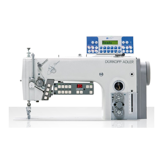
Machine description Machine description Components of the machine Fig. 1: Components of the machine ① ② ⑩ ③ ⑨ ④ ⑧ ⑤ ⑥⑦ (1) - Winder (6) - Preliminary tension (2) - Adjusting wheel sewing foot (7) - Oil reservoir pressure/downforce pressure (8) - Stitch length adjusting wheels (3) - Locking button... -
Page 18: Proper Use
Machine description Proper use WARNING Risk of injury from live, moving and cutting parts as well as from sharp parts! Improper use can result in electric shock, crushing, cutting and punctures. Follow all instructions provided. NOTICE Non-observance will lead to property damage! Improper use can result in material damage at the machine. -
Page 19: Declaration Of Conformity
Machine description Declaration of Conformity The machine complies with European regulations ensuring health, safety, and environmental protection as specified in the declara- tion of conformity or in the declaration of incorporation. Operating Instructions 275 - 02.0 - 08/2019... - Page 20 Machine description Operating Instructions 275 - 02.0 - 08/2019...
-
Page 21: Operation
Operation Operation The operating sequence consists of several different steps. Fault-free operation is necessary in order to achieve a good sewing result. Preparing the machine for operation WARNING Risk of injury from moving, cutting and sharp parts! Crushing, cutting and punctures are possible. If possible, make preparations only when the machine is switched off. -
Page 22: Switching On And Off The Machine
Operation Switching on and off the machine Fig. 2: Switching on and off the machine ① ② (1) - Main switch (2) - LED To switch on the machine: Press the main switch (1) into position I. The LED (2) lights up. To switch off the machine: Press the main switch (1) into position 0. -
Page 23: Inserting Or Changing The Needle
Operation Inserting or changing the needle CAUTION Risk of injury from sharp parts! Puncture possible. Switch off the machine before inserting or changing the needle. NOTICE Property damage may occur! Damage to the machine, needle breakage, or thread damage is possible due to an incorrect clearance between the needle and hook tip. - Page 24 Operation Fig. 3: Inserting or changing the needle ① ④ ② ③ (1) - Needle bar (3) - Hook (2) - Screw (4) - Groove To insert or change the needle: Turn the handwheel until the needle bar (1) reaches the top dead centre.
-
Page 25: Threading The Needle Thread
Operation Threading the needle thread CAUTION Risk of injury from sharp parts! Puncture possible. Swtich off the machine before threading the needle thread. Fig. 4: Threading the needle thread (1) ① ② (1) - Thread guide (2) - Thread reel holder To thread the needle thread: Fit the thread reel on the thread reel holder (2). - Page 26 Operation Fig. 5: Threading the needle thread (2) ⑫ ⑪ ⑩ ③ ⑨ ⑧ ④ ⑤ ⑥ ⑦ (3) - Thread lever (8) - Thread tensioning spring (4) - Hook (9) - Needle thread regulator (5) - Thread clamp (10) - Pre-tension (6) - Hook (11) - Thread guide (7) - Main tension...
- Page 27 Operation Fig. 6: Threading the needle thread (3) ③ ④ ⑮ ⑭ ⑤ ⑬ (3) - Thread lever (13) - Needle eye (4) - Hook (14) - Thread guide (5) - Thread clamp (15) - Thread guide 12. Insert the thread from the right to the left through the thread lever (3).
-
Page 28: Winding The Hook Thread
Operation Winding the hook thread NOTICE Property damage may occur! Risk of damaging the machine when winding without material to be sewn. Lock the sewing foot in place. Take the thread out of the thread lever and the bobbin capsule out of the hook if you wind on the hook thread without sewing the material in the process. - Page 29 Operation Fig. 8: Winding the hook thread (2) ③ ④ ⑤ ⑥ ⑦ (3) - Winder tension (6) - Cutting clamp (4) - Thread guide (7) - Bobbin winder flap (5) - Bobbin shaft Fit the empty bobbin onto the bobbin shaft (5). Insert the thread from the right to the left through the thread guide (4).
-
Page 30: Changing The Bobbin
Operation Changing the bobbin Fig. 9: Changing the bobbin ① ⑤ ④ ② ③ (1) - Bobbin case upper section (4) - Tensioning spring (2) - Bobbin case retainer (5) - Hole (3) - Bobbin To change the bobbin: Tilt the machine head. Raise the bobbin case retainer (2). -
Page 31: Thread Tension
Operation Thread tension Together with the hook thread tension, the needle thread tension influences the final seam pattern. With thin sewing material, excessive thread tension can lead to undesired gathering and thread breakage. Proper setting If the tension of needle thread and hook thread is identical, the thread interlacing lies in the middle of the sewing material. -
Page 32: Setting The Needle Thread Tension
Operation 4.7.1 Setting the needle thread tension Main tension Fig. 11: Setting the needle thread tension (1), Main tension ① (1) - Adjusting wheel main tension The main tension (1) determines the normal tension during se- wing. Proper setting The main tension should be set as low as possible. The thread interlacing should be exactly in the middle of the material being sewn. - Page 33 Operation Pre-tension Fig. 12: Setting the needle thread tension (2), Pre-tension ① ② (1) - Adjusting wheel pre-tension (2) - Bolt The pre-tension (1) holds the thread in position while the main tensioner is open when cutting the thread. The pre-tension (1) also determines the length of the initial thread for the new seam when the thread is cut: Proper setting In the basic position, the upper side of the adjusting wheel for the...
-
Page 34: Setting The Hook Thread Tension
Operation 4.7.2 Setting the hook thread tension Fig. 13: Setting the hook thread tension (1) ④ ① ③ ② (1) - Bobbin (3) - Tensioning spring (2) - Braking spring (4) - Screw The braking spring (2) and tensioning spring (3) together deter- mine the hook thread tension. -
Page 35: Setting The Needle Thread Regulator
Operation Insert the spool housing together with the bobbin into the hook. Hold tight the free thread end with one hand. Turn the handwheel until the sewing machine carries out one stitch. Pull the hook thread onto the upper side of the needle hole using the needle thread. - Page 36 Operation Fig. 14: Setting the needle thread regulator (1) ① ② (1) - Hook (2) - Needle thread loop Proper setting The needle thread loop (2) slides at low tension over the thickest point of the hook (1). Fig. 15: Setting the needle thread regulator (2) ③...
-
Page 37: Setting The Stitch Length
Operation Setting the stitch length The stitch length can be continuously adjusted between 1 and 4 mm by turning the adjusting wheels on the machine column. The upper adjusting wheel is for the stitch length when sewing forwards and the lower adjusting wheel is for the stitch length when sewing in reverse. -
Page 38: Upper Transport (Multiple Width)
Operation 4.10 Upper transport (Multiple width) 4.10.1 Setting the upper transport length When the stitch length for sewing forwards is changed at the adjusting wheel the upper transport length is automatically adjus- ted to suit. Fig. 17: Setting the upper transport length ①... -
Page 39: Setting The Second Upper Transport Length (Optional)
Operation 4.10.2 Setting the second upper transport length (optional) When using mechanically or electropneumatically switched mul- tiple widths (additional equipment) a second (larger) upper trans- port length can be set at the adjusting wheel. Fig. 18: Setting the second upper transport length ①... -
Page 40: Limiting The Upper Transport Length
Operation 4.10.3 Limiting the upper transport length Certain equipment requires the maximum upper transport length to be limited to a value less than 8 mm. The limiter for this is supplied with the corresponding sewing equipment. Fig. 19: Limiting the upper transport length ①... -
Page 41: Sewing Foot
Operation 4.11 Sewing foot CAUTION Risk of injury from moving parts! Crushing possible. DO NOT place your hands under the sewing foot. 4.11.1 Setting the sewing foot pressure The adjusting wheel on the machine head determines the contact pressure of the sewing foot on the material to be sewn. The pressure can be adjusted continuously by turning the wheel. - Page 42 Operation Fig. 20: Setting the sewing foot pressure ① ② (1) - Adjusting wheel (2) - Counternut To set the sewing foot pressure: Loosen the counternut (2). Turn the adjusting wheel (1): • To increase the sewing foot pressure: Turn the adjus- ting wheel (1) clockwise •...
-
Page 43: Setting The Downforce Pressure For The Upper Transport Foot
Operation 4.11.2 Setting the downforce pressure for the upper transport foot The downforce pressure for the upper transport foot (gripper transport) is set using the adjusting wheel on the machine head. The pressure can be adjusted continuously by turning the wheel. Proper setting The material being sewn does not slip and is correctly transported. -
Page 44: Lifting The Sewing Foot
Operation 4.11.3 Lifting the sewing foot The sewing foot can be lifted mechanically using the knee switch or electromagnetically using the pedal to insert or move the ma- terial being sewn. Fig. 22: Lifting the sewing foot ① ② (1) - Knee switch (2) - Pedal To lift the sewing foot with the knee switch: Push the knee switch (1) to the right. -
Page 45: Locking The Sewing Foot
Operation 4.11.4 Locking the sewing foot The button on the machine head can be used to hold the lifted sewing foot in the upper position, e. g. in order to wind the hook thread. Fig. 23: Locking the sewing foot ①... -
Page 46: Edge Cutter
Operation 4.12 Edge cutter The lowering and raising of the edge cutter is defined via the parameter settings in the control ( Operating manual DAC basic/classic). The cutting speed of the edge cutter is defined via a 3-position switch. The positioning of the switch depends on whether or not the DAC mini control is used. -
Page 47: Setting The Edge Cutter With A Dac Mini
Operation 4.12.2 Setting the edge cutter with a DAC mini On machines with a DAC mini the switch for the edge cutter is located on the rear side of the DAC mini under the table plate. Fig. 25: Setting the edge cutter with a DAC mini ①... -
Page 48: Enabling The Edge Cutter With A Dac Mini
Operation 4.12.3 Enabling the edge cutter with a DAC mini The edge cutter must be enabled via the DAC mini for every sequence in which it is to work ( p. 92). To enable the edge cutter with a DAC mini: Press the F button on the DAC mini control panel. -
Page 49: Sewing
Operation Element Function/Meaning Manual reverse sewing The machine sews in reverse while the button is pres- sed. Edge cutter Switch the edge cutter on and off. Multiple width Switch additional multiple widths on and off. Yellow LED Lights up when a function is activated. Green LED Lights up when the sewing drive is switched on. - Page 50 Operation Fig. 27: Sewing ① (1) - Pedal To sew: Press the pedal (1) to POS. -1. Lift the sewing feet. Slide the sewing material up to the needle. Press the pedal (1) to POS. 1 and hold it down. ...
- Page 51 Operation Options during sewing Process Description Stopping sewing Press the pedal to POS. 0. The machine stops. The needle is down. The sewing foot is down. Continue the sewing Press the pedal to POS. 1. process The machine sews at the speed speci- fied by the pedal.
- Page 52 Operation Operating Instructions 275 - 02.0 - 08/2019...
-
Page 53: Programming
Programming Programming DAC mini The DAC mini allows programming and semi-automatic calling of different multiple widths within a seam. You can save up to 30 different programs, each with up to 8 different multiple width sequences. The current multiple width is shown in the display in every sequence and can be manually changed at any time. - Page 54 Programming Button Function Sequence buttons 1 to 8 Each of the sequence buttons can be assigned its own upper transport value via the Plus/Minus buttons. The LEDs above the buttons indicate the following sta- tes: • Red LED on = sequence is active •...
-
Page 55: Smooth Sewing
Programming Information The machine performs an internal system self-test when switched on. The machine is not ready for operation during this self-test. On completion of the system self-test the last program used is briefly shown in the display. After this, the LED above the button for the first active sequence of this program is switched on and the associated upper transport length is displayed. -
Page 56: Sewing With Multiple Widths
Programming 5.1.2 Sewing with multiple widths To sew with multiple widths: Deactivate all sequence buttons that are not required: To do this, press the corresponding sequence button and the Activation/deactivation button at the same time. The red LEDs above the deactivated buttons light up. If the button for the desired sequence is deactivated (red LED is lit): Activate all sequence buttons that are not required: To do this, press the corresponding sequence button and the... -
Page 57: Changing Between Smooth Sewing And A Single Multiple Width
Programming 5.1.3 Changing between smooth sewing and a single multiple width To change between smooth sewing and a single multiple width: Press the button and the button for the desired multiple width sequence at the same time. The green LEDs above both buttons light up. Changing between smooth sewing and multiple width: Actuate the knee switch (or at the end of the seam, press the pedal all the way back to cut the thread). -
Page 58: Alternately Sewing Left And Right Parts With Programmed Multiple Widths
Programming Information If the desired multiple width cannot be achieved in a sequence then the upper transport length can be changed using the Plus/ Minus buttons. The change is saved as soon as the next sequence is switched to. 5.1.5 Alternately sewing left and right parts with programmed multiple widths To sew alternately left and right parts with programmed multiple... -
Page 59: Switching On Or Off The Edge Cutter
Programming 5.1.7 Switching on or off the edge cutter On machines with an edge cutter, this must be enabled for every sequence and for smooth sewing ( p. 46). To switch on the edge cutter: In the sequence before the start of sewing, press the button ... -
Page 60: Creating And Changing A Program
Programming Press the button The LED above the button goes out. The program selection function exits. The selected program is activated. 5.1.9 Creating and changing a program All changes to sequences and programs are immediately adopted and are save on the transition to the next step. To create or change a program: Set the desired program number (... -
Page 61: Dac Basic/Classic
Programming DAC basic/classic All software settings are performed using the OP1000 control panel. The control panel is composed of a display and buttons. Using the control panel you can: • Use groups of buttons to select machine functions • Read service and error messages. Information This chapter describes the machine-specific functions of the OP1000 control panel. - Page 62 Programming OP1000 buttons and functions Button Function Thread button group Start bartack • Sets the start bartack Multiple start bartack • Sets the multiple start bartack End bartack • Sets the end bartack Multiple end bartack • Sets the multiple end bartack Thread cutter •...
- Page 63 Programming Button Function Speed • Reduces the motor speed Function button • Activates or deactivates any stored function Programming button group • Ends parameter mode • Increases parameter • Changes user level • Selects subprogram • Increases parameter • Changes to next higher category •...
- Page 64 Programming Button Function • Decreases parameter • Changes user level • Selects subprogram • Decreases parameter • Changes to next lower category • Selects subprogram • Decreases parameter • Selects subprogram • Decreases parameter • Selects subprogram Reset • Resets the (piece) counter Operating Instructions 275 - 02.0 - 08/2019...
- Page 65 Programming Button Function Seam program button group Seam program I • Activates seam program I Seam program II • Activates seam program II Seam program III • Sets seam program III Operating Instructions 275 - 02.0 - 08/2019...
- Page 66 Programming Operating Instructions 275 - 02.0 - 08/2019...
-
Page 67: Maintenance
Maintenance Maintenance WARNING Risk of injury from sharp parts! Punctures and cutting possible. Prior to any maintenance work, switch off the machine or set the machine to threading mode. WARNING Risk of injury from moving parts! Crushing possible. Prior to any maintenance work, switch off the machine or set the machine to threading mode. -
Page 68: Cleaning
Maintenance Cleaning WARNING Risk of injury from flying particles! Flying particles can enter the eyes, causing injury. Wear safety goggles. Hold the compressed air gun so that the particles do not fly close to people. Make sure no particles fly into the oil pan. NOTICE Property damage from soiling! Lint and thread remnants can impair the operation of the... -
Page 69: Lubricating
Maintenance Lubricating CAUTION Risk of injury from contact with oil! Oil can cause a rash if it comes into contact with skin. Avoid skin contact with oil. If oil has come into contact with your skin, wash the affected areas thoroughly. NOTICE Property damage from incorrect oil! Incorrect oil types can result in damage to the machine. -
Page 70: Lubricating The Machine Head
Maintenance You can order the lubricating oil from our sales offices using the following part numbers. Container Part no. 250 ml 9047 000011 9047 000012 9047 000013 9047 000014 6.2.1 Lubricating the machine head Fig. 30: Lubricating the machine head ①... -
Page 71: Lubricating The Hook
Maintenance 6.2.2 Lubricating the hook Fig. 31: Lubricating the hook ① (1) - Oil reservoir Proper setting The oil level must always be between the MIN mark and the MAX mark. To lubricate the hook: Switch off the machine. Tilt the machine head. Check oil quantity in oil reservoir (1). -
Page 72: Servicing The Pneumatic System
Maintenance Servicing the pneumatic system 6.3.1 Setting the operating pressure NOTICE Property damage from incorrect setting! Incorrect operating pressure can result in damage to the machine. Ensure that the machine is only used when the operating pressure is set correctly. Proper setting Refer to the Technical data (... -
Page 73: Draining The Water Condensation
Maintenance Turn the pressure controller until the pressure gage (2) indicates the proper setting: • Increase pressure = turn clockwise • Reduce pressure = turn counterclockwise Push the pressure controller (1) down. 6.3.2 Draining the water condensation NOTICE Property damage from excess water! Excess water can cause damage to the machine. -
Page 74: Cleaning The Filter Element
Maintenance Place the collection tray under the drain screw (3). Loosen the drain screw (3) completely. Allow water to drain into the collection tray. Tighten the drain screw (3). Connect the machine to the compressed air supply. 6.3.3 Cleaning the filter element NOTICE Damage to the paintwork from solvent-based cleaners! Solvent-based cleaners damage the filter. -
Page 75: Parts List
Maintenance Wash out the filter tray using benzine. Tighten the filter element (1). Tighten the water separator (2). Tighten the drain screw (3). 10. Connect the machine to the compressed air supply. Parts list A parts list can be ordered from Dürkopp Adler. Or visit our website for further information at: www.duerkopp-adler.com Operating Instructions 275 - 02.0 - 08/2019... - Page 76 Maintenance Operating Instructions 275 - 02.0 - 08/2019...
-
Page 77: Setup
Setup Setup WARNING Risk of injury from cutting parts! Cutting injuries may be sustained while unpacking and setting up the machine. Only qualified specialists may set up the machine. Wear safety gloves WARNING Risk of injury from moving parts! Crushing injuries may be sustained while unpacking and setting up the machine. -
Page 78: Assembling The Stand
Setup Assembling the stand Fig. 35: Assembling the stand ① ② ① ② ④ ③ ④ ⑤ (1) - Head sections (4) - Foot struts (2) - Stand bars (5) - Cross strut (3) - Cross bars To assemble the stand: Screw the cross bars (3) onto the stand bars (2). -
Page 79: Tabletop
Setup Tabletop Ensure that the tabletop has sufficient load-bearing capacity and strength. 7.4.1 Completing the tabletop Fig. 36: Completing the tabletop (1) ② ① ③ ④ ⑤ ⑥ (1) - Machine head support (4) - Drawer (2) - Pubber inlays (5) - Cable duct (3) - Rest plugs (6) - Oil pan... - Page 80 Setup Information Machines with edge cutter Fig. 37: Completing the tabletop (2) ⑦ ⑥ (6) - Oil pan (7) - Waste chute To assemble the waste chute for machines with edge cutter: Center punch the screw positions of the waste chute (7) and screw the waste chute into position under the table plate cutout.
-
Page 81: Assembling The Tabletop To The Stand
Setup 7.4.2 Assembling the tabletop to the stand Machines without DAC mini Fig. 38: Machines without DAC mini To assemble the tabletop to the stand Fasten the table plate to the stand with wood screws according to the dimensions shown above. Machines with DAC mini For machines with a DAC mini multiple width controller and edge cutter, in addition to the normal steps for completing the... - Page 82 Setup Fig. 39: Machines with DAC mini ③ ② ① ④ ⑥ ⑦ ⑤ (1) - Sewing lamp transformer (5) - Positioin for sewing lamp trans- (2) - DAC mini former (3) - Distribution box (6) - Position for DAC mini (4) - Knee switch (7) - Position for Distribution box To assemble the DAC mini components:...
-
Page 83: Assembling The Reel Stand
Setup 7.4.3 Assembling the reel stand Fig. 40: Assembling the reel stand ① ② ③ (1) - Thread guide (3) - Thread reel holders (2) - Reel stand To assemble the reel stand: Insert the thread stand (1) into the hole. Fasten the thread stand (1) with nut and washer. -
Page 84: Setting The Working Height
Setup Setting the working height WARNING Risk of injury from moving parts! The tabletop can sink under its own weight when the screws on the stand bars are loosened. Crushing possible. Ensure that your hands are not jammed when loosening the screws. CAUTION Risk of musculoskeletal damage from incorrect setting! - Page 85 Setup Fig. 41: Setting the working height ① ① (1) - Screws To set the working height: Loosen the screws (1). Set the tabletop to the desired height. Important Pull out or push in the tabletop evenly at both sides to prevent it from jamming.
-
Page 86: Assembling The Pedal And The Setpoint Device
Setup Assembling the pedal and the setpoint device 7.6.1 Machines without DAC mini Fig. 42: Machines without DAC mini ① ② ③ ④ ⑤ ⑥ (1) - Angle (4) - Pedal rod (2) - Setpoint device (5) - Pedal (3) - Screw (6) - Cross strut To assemble the pedal and the setpoint device: Fit the pedal (5) onto the cross strut (6) and align it. -
Page 87: Machines With Dac Mini
Setup Hang the pedal rod (4) with the ball socket on the setpoint device (2) and attach to the pedal (5). Pull the pedal rod (4) to the correct length. Proper setting The pedal is correctly adjusted if it has an inclination of 10° when released. -
Page 88: Inserting The Machine Head
Setup Inserting the machine head WARNING Risk of injury! The machine head is heavy and can cause crushing injuries if handled in a careless manner. NEVER stick your hands between machine head and tabletop. Fig. 44: Inserting the machine head ①... -
Page 89: Assembling The Control
Setup Assembling the control Fig. 45: Assembling the control ② ① ③ (1) - Strain relief (3) - Control (2) - Screw holder To assemble the control: Screw the control (3) onto the screw holders (2) under the tabletop. Clamp the power cable of the control into the strain relief (1). Screw the strain relief (1) under the tabletop. -
Page 90: Assembling The Knee Switch
Setup Assembling the knee switch The knee switch is screwed under the table plate. Different posi- tions are used for machines without a DAC mini and machines with a DAC mini. Fig. 46: Assembling the knee switch Machines without DAC mini ①... -
Page 91: Electrical Connection
Setup 7.10 Electrical connection DANGER Risk of death from live components! Unprotected contact with electricity can result in serious injuries or death. Only qualified specialists may perform work on electrical equipment. Important The voltage on the type plate of the sewing motor must correspond to the mains voltage. -
Page 92: Creating The Equipotential Bonding
Setup 7.10.2 Creating the equipotential bonding The earthing cable conducts away any static charging to ground. Fig. 47: Creating the equipotential bonding ② ① ③ (1) - Screw (3) - Cable lug (2) - earthing cable To create the equipotential bonding: Attach the earthing cable (2) to the motor using the screw (1). -
Page 93: Checking The Needle Positions
Setup 7.11 Checking the needle positions The needle positions were correctly set before delivery. Despite this, the needle positions should be checked before starting the machine. Order The following requirements must be satisfied for performing the test: • Sewing foot locked in place in the upper position •... -
Page 94: Setting The Dac Mini Multiple Width Control
Setup 7.12 Setting the DAC mini multiple width control Fig. 48: Setting the DAC mini multiple width control ① ② ③ ④ ⑤ ⑥ ⑦ (1) - Button smooth sewing (5) - Activation/Deactivation button (2) - Sequence buttons (6) - Button F (Enable/Function) (3) - Display (7) - Direction change button (4) - Plus-/Minus-buttons... - Page 95 Setup Setting the brightness of the LEDs and the display To set the brightness of the LEDs and the display: After calling up the special functions, press sequence button 2. All LEDs are switched on. The display (3) shows the Brightness selection: Set the brightness using the buttons Information...
- Page 96 Setup Moving to the reference position after every thread-cutting operation After switching on the machine the stepper motor for setting the length of the upper transport moves to the reference position once. To allow the position of the stepper motor to be checked more frequently, the stepper motor can also be moved to the reference position after every thread-cutting operation.
- Page 97 Setup Continue switching the sewing sequence via thread cutting When sewing multiple widths in a program the next sequence is usually activated by cutting the thread. 3 methods of switching the next sequence via thread cutting are available: To continue switching the sewing sequence via thread cutting: After calling up the special functions, press sequence button 5.
-
Page 98: Checking The Rotation To The Reference Position
Setup 7.13 Checking the rotation to the reference position WARNING Risk of injury from moving parts! Crushing possible. Do NOT reach into the area of moving machine parts while testing the reference position. Each time the machine is switched on the stepper motor rotates to the reference position and then returns to the current upper transport length in order to set the upper transport length. -
Page 99: Pneumatic Connection
Setup 7.14 Pneumatic connection NOTICE Property damage from oily compressed air! Oil particles in the compressed air can cause malfunctions of the machine and soil the sewing material. Ensure that no oil particles enter the compressed air supply. NOTICE Property damage from incorrect setting! Incorrect system pressure can result in damage to the machine. -
Page 100: Assembling The Compressed Air Maintenance Unit
Setup 7.14.1 Assembling the compressed air maintenance unit Fig. 50: Assembling the compressed air maintenance unit ④ ③ ① ② (1) - Cross bar (3) - Compressed air maintenance (2) - Connection hose unit (4) - Machine hose So montieren Sie die Druckluft-Wartungseinheit: Attach the compressed air maintenance unit (3) to the cross bar (1) of the stand using the bracket, screws and clip. -
Page 101: Setting The Operating Pressure
Setup 7.14.2 Setting the operating pressure NOTICE Property damage from incorrect setting! Incorrect operating pressure can result in damage to the machine. Ensure that the machine is only used when the operating pressure is set correctly. Proper setting Refer to the Technical data ( p. 109) chapter for the permis- sible operating pressure. -
Page 102: Performing A Test Run
Setup 7.15 Performing a test run When setup is complete, perform a test run to check the functio- nality of the machine. Operating Instructions 275 - 02.0 - 08/2019... -
Page 103: Decommissioning
Decommissioning Decommissioning WARNING Risk of injury from a lack of care! Serious injuries may occur. ONLY clean the machine when it is switched off. Allow ONLY trained personnel to disconnect the machine. CAUTION Risk of injury from contact with oil! Oil can cause a rash if it comes into contact with skin. - Page 104 Decommissioning Operating Instructions 275 - 02.0 - 08/2019...
-
Page 105: Disposal
Disposal Disposal CAUTION Risk of environmental damage from improper disposal! Improper disposal of the machine can result in serious environmental damage. ALWAYS comply with the national regulations regarding disposal. The machine must not be disposed of in the normal household waste. - Page 106 Disposal Operating Instructions 275 - 02.0 - 08/2019...
-
Page 107: Troubleshooting
Troubleshooting 10 Troubleshooting 10.1 Customer Service Contact for repairs and issues with the machine: Dürkopp Adler AG Potsdamer Str. 190 33719 Bielefeld, Germany Tel. +49 (0) 180 5 383 756 Fax +49 (0) 521 925 2594 Email: service@duerkopp-adler.com Internet: www.duerkopp-adler.com Operating Instructions 275 - 02.0 - 08/2019... -
Page 108: Errors In Sewing Process
Troubleshooting 10.2 Errors in sewing process Error Possible causes Remedial action Unthreading Needle thread tension is Check needle thread at seam too firm tension beginning Thread Needle thread and hook Check threading path breaking thread have not been threaded correctly Needle is bent or Replace the needle sharp-edged... - Page 109 Troubleshooting Error Possible causes Remedial action Missing Needle thread and hook Check threading path stitches thread have not been threaded correctly Needle is blunt or bent Replace the needle Needle is not inserted Insert the needle correctly correctly into the needle into the needle bar The needle thickness used Use recommended needle...
- Page 110 Troubleshooting Operating Instructions 275 - 02.0 - 08/2019...
-
Page 111: Technical Data
Technical Data 11 Technical Data Noise emission Workplace-specific emission value as per DIN EN ISO 10821: = 79,5 dB (A); K = 0,38 dB (A) • Stitch length: 3,2 mm • Speed: 4100 rpm • Sewing material: 2-layer material G1 DIN 23328 11.1 Data and characteristic values Technical Data Unit... -
Page 112: Requirements For Trouble-Free Operation
Technical Data Technical Data Unit Height [mm] Weight [kg] Power input [kVA] 11.2 Requirements for trouble-free operation Compressed air quality must be ensured in accordance with ISO 8573-1: 2010 [7:4:4]. Operating Instructions 275 - 02.0 - 08/2019... -
Page 113: Appendix
Appendix 12 Appendix Wiring diagram Fig. 52: Wiring diagram Operating Instructions 275 - 02.0 - 08/2019... - Page 114 Appendix Fig. 53: Wiring diagram Operating Instructions 275 - 02.0 - 08/2019...
- Page 115 Appendix Fig. 54: Wiring diagram Operating Instructions 275 - 02.0 - 08/2019...
- Page 116 Appendix Fig. 55: Wiring diagram Operating Instructions 275 - 02.0 - 08/2019...
- Page 117 Appendix Fig. 56: Wiring diagram Operating Instructions 275 - 02.0 - 08/2019...
- Page 118 Appendix Operating Instructions 275 - 02.0 - 08/2019...
- Page 120 DÜRKOPP ADLER AG...
Need help?
Do you have a question about the 275 Series and is the answer not in the manual?
Questions and answers