HP 8924C Application Manual
Cdma mobile station test set
Hide thumbs
Also See for 8924C:
- User manual (350 pages) ,
- Assembly (640 pages) ,
- Reference manual (469 pages)
Table of Contents
Advertisement
Quick Links
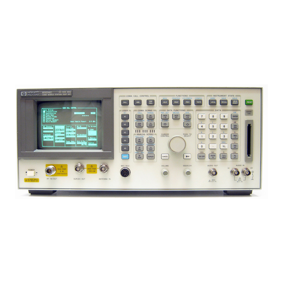
HP 8924C CDMA Mobile Station Test Set
POWER
!
MAX PWR
6 W
DO NOT APPLY
!
RF WHEN OFF
RF IN/OUT
DUPLEX OUT
Application Guide
Firmware Version A.06.25 and above
CDMA CALL CONTROL
END
CALL
ANS
CALL
USER
CDMA SCRNS
k1'
CELL
RANGE
CALL
RX
k1
CTRL
TEST
k2'
SPECTRUM
MSRPT
GEN
TX
k2
CTRL
TEST
k3'
k3
ANALOG SCRNS
ASSIGN
ENCODER
DECODER
RF
RX
k4
ANL
TEST
RELEASE
ACP
AF
TX
k5
ANL
TEST
SPEC ANL
SCOPE
RF
SHIFT
DUPLEX
GEN
MIC/ACC
!
MAX PWR
200 mW
ANTENNA IN
HP Part No. 08924-90021
Printed in U. S. A.
December 1998
Rev. G
FUNCTIONS
INSTRUMENT STATE
MSG
PRINTER
I/O CONFIG
CONFIG
ADRS
SAVE
HELP
PRINT
PREV
TESTS
LOCAL
RECALL
DATA FUNCTIONS
DATA
REF SET
METER
AVG
INCR
INCR
INCR X10
7
8
9
: 10
SET
LO LIMIT
HI LIMIT
4
5
6
CURSOR
PUSH TO
CONTROL
SELECT
1
2
3
+ _
0
YES
NO
ppm
ON/OFF
CANCEL
W
dBµV
VOLUME
SQUELCH
AUDIO OUT
HI
MAX
!
12 v Pk
HOLD
MEAS
PRESET
RESET
MEMOR
Y CARD
ENTER
dB
GHz
dBm
%
MHz
V
s
kHz
mV
Ω
ms
%
Hz
µV
AUDIO IN
LO
MAX
!
42 v Pk
1
Advertisement
Table of Contents

Related Manuals for HP 8924C


Summary of Contents for HP 8924C
- Page 1 HP 8924C CDMA Mobile Station Test Set Application Guide Firmware Version A.06.25 and above CDMA CALL CONTROL FUNCTIONS INSTRUMENT STATE PRINTER I/O CONFIG CONFIG ADRS SAVE HOLD MEAS CALL HELP PRINT PREV TESTS LOCAL RECALL PRESET CALL RESET MEMOR Y CARD...
- Page 2 Copyright © Hewlett-Packard Company 1995 Notice Information contained in this document is subject to change without notice. All Rights Reserved. Reproduction, adaptation, or translation without prior written permission is prohibited, except as allowed under the copyright laws. This material may be reproduced by or for the U.S. Government pursuant to the Copyright License under the clause at DFARS 52.227-7013 (APR 1988).
- Page 3 Manufacturer’s Declaration This statement is provided to comply with the requirements of the German Sound Emission Directive, from 18 January 1991. This product has a sound pressure emission (at the operator position) < 70 dB(A). Sound Pressure Lp < 70 dB(A). •...
- Page 4 Safety GENERAL Considerations This product and related documentation must be reviewed for familiarization with safety markings and instructions before operation. This product has been designed and tested in accordance with IEC Publication 1010, "Safety Requirements for Electronic Measuring Apparatus," and has been supplied in a safe condition.
- Page 5 Safety Considerations for this Instrument WARNING This product is a Safety Class I instrument (provided with a protective earthing ground incorporated in the power cord). The mains plug shall only be inserted in a socket outlet provided with a protective earth contact. Any interruption of the protective conductor inside or outside of the product is likely to make the product dangerous.
- Page 6 CAUTION: Always use the three-prong ac power cord supplied with this product. Failure to ensure adequate earth grounding by not using this cord may cause product damage. This product is designed for use in Installation Category II and Pollution Degree 2 per IEC 1010 and IEC 664 respectively.
- Page 7 For warranty service or repair, this product must be returned to a service facility designated by HP. Buyer shall prepay shipping charges to HP and HP shall pay shipping charges, duties, and taxes for products returned to HP from another country.
- Page 8 24001 E. Mission Avenue Liberty Lake, Washington 99019-9599 declares that the product CDMA Mobile Station Test Set Product Name: HP 8924C Model Number: This declaration covers all options of the above Product Options: product. conforms to the following Product specifications:...
-
Page 9: Table Of Contents
Contents 1 Calibrating the Test Set Calibration Procedures 24 Guidelines: 24 Recommended Calibration Procedures: 25 Calibrating CDMA Channel Levels 26 Calibrating Channel Power Measurements 29 Procedure Overview 33 Calibrating RF Generator Levels 35 Zeroing Average Power Measurements 36 Procedure Overview 40 Correcting for RF Path Loss 41 Determining RF Path Loss 44 Procedure Prerequisites 44... - Page 10 Contents 2 Setting Up a Call Setting up a Call 52 Procedure Overview 66 Problem Solving 68 Checklist 1. MSUT did not find service 68 Checklist 2. Registration failed 70 N:\mkt\MANUALS\HP8924C\APPMOD\BOOK\APPMOD.TOC...
- Page 11 Contents 3 CDMA Receiver Tests List of CDMA Receiver Tests 72 Measuring Demodulation of Forward Traffic Channel with AWGN 73 Test Prerequisites 73 Measurement Overview 82 HPBASIC Programming Example 83 Measuring Receiver Sensitivity and Dynamic Range 87 Measurement Overview 95 HPBASIC Programming Example 96 Measuring Single Tone Desensitization 99 Test Prerequisites 99...
- Page 12 Contents 4 CDMA Transmitter Tests List of CDMA Transmitter Tests 140 Measuring Waveform Quality 141 Measurement Overview 147 HPBASIC Program Example 148 Measuring Minimum/Maximum Power 150 Test Prerequisites 150 Measurement Overview 153 Measuring Maximum RF Output Power 154 Test Prerequisites 154 Measurement Overview 161 HPBASIC Programming Example 162 Measuring Minimum Controlled Output Power 164...
- Page 13 Contents 5 CDMA to Analog Handoff Performing a CDMA to Analog Handoff 200 HP BASIC Example 208 Procedure Overview 209 N:\mkt\MANUALS\HP8924C\APPMOD\BOOK\APPMOD.TOC...
- Page 14 Contents 6 Authentication Tests List of CDMA Authentication Tests 212 Initializing SSD to Zero 213 Measurement Overview 221 Updating SSD 222 Measurement Overview 229 Performing a Unique Challenge-Response 230 Measurement Overview 237 N:\mkt\MANUALS\HP8924C\APPMOD\BOOK\APPMOD.TOC...
- Page 15 Contents 7 Short Message Service Tests List of CDMA SMS Tests 240 Sending Short Messages on the Paging/Access Channels 241 Measurement Overview 249 Sending Short Messages on the Traffic Channels 250 Measurement Overview 258 N:\mkt\MANUALS\HP8924C\APPMOD\BOOK\APPMOD.TOC...
- Page 16 Contents 8 Establishing HP-IB Communication Setting Up HP-IB Control 260 N:\mkt\MANUALS\HP8924C\APPMOD\BOOK\APPMOD.TOC...
- Page 17 Conditioning the Test Set for Call Processing 279 Analog Call Processing Subsystem HP-IB Error Messages 280 Reading An Analog Call Processing Subsystem HP-IB Error Messages 280 Call Processing Status Register Group 281 Using the Call Processing Status Register Group To Control Program Flow 281...
- Page 18 Contents Using the CALL CONTROL Screen to test AMPS Authentication 292 Condition the Test Set for Call Processing 292 Configure the Test Set 293 Turn on the Test Set’s Control Channel 294 Initialize Call Processing with Authentication 294 Page a Mobile Station with Authentication 296 Originate a Call with Authentication 296 Perform an SSD Update 297 Perform a Unique Challenge 299...
- Page 19 Contents 10 Controlling Program Flow Using Service Request (SRQ) Interrupts 318 Controlling Program Flow Procedure 319 Examples Used in this Procedure 319 Example BASIC Program to Set Up and Service an SRQ Interrupt 328 N:\mkt\MANUALS\HP8924C\APPMOD\BOOK\APPMOD.TOC...
- Page 20 Contents 11 Protocol Logging Hardware and Software Requirements 335 Hardware Requirements 335 Software Requirements 336 Connecting the Test Set to the Computer 337 Setting Up the Communications Package 339 General Setup Parameters 339 Installing PROCOMM PLUS 339 Reconfiguring PROCOMM PLUS 340 Logging Protocol Messages 342 Capturing a Log to a File on the Computer 344 Control Commands for Protocol Logging 345...
- Page 21 Contents Index 351 N:\mkt\MANUALS\HP8924C\APPMOD\BOOK\APPMOD.TOC...
- Page 22 Contents N:\mkt\MANUALS\HP8924C\APPMOD\BOOK\APPMOD.TOC...
-
Page 23: Calibrating The Test Set
Chapter 1 Calibrating The Test Set... -
Page 24: Calibration Procedures
The list below shows all of the calibration procedures that must be performed periodically when testing CDMA mobile stations with the Test Set, including Test Sets configured with an HP 83236B PCS Interface. "Calibrating CDMA Channel Levels" on page 26 "Calibrating Channel Power Measurements"... -
Page 25: Recommended Calibration Procedures
Chapter 1, Calibrating the Test Set Calibration Procedures Recommended Calibration Procedures: "Calibrating "Calibrating "Zeroing "Calibrating RF CDMA Channel Channel Power Average Power Generator Levels" Levels" on page 26 Measurements" Measurements" on page 35 on page 29 on page 36 (PCB CAL) When Test Set is being used for the first time (allow... -
Page 26: Calibrating Cdma Channel Levels
Chapter 1, Calibrating the Test Set Calibrating CDMA Channel Levels Calibrating CDMA Channel Levels Approximate time: 8 minutes CDMA channel levels should be calibrated whenever any of the following events occur: • After a 30-minute warm-up period • After firmware is upgraded •... - Page 27 The TESTS (Main Menu) screen provides access to the Test Set’s internal IBASIC controller. You can load, run, and customize procedures on this screen. HP-IB Syntax "DISP TEST" ! displays the TESTS (Main Menu) screen. "TEST:PROC:LOC ’ROM’" ! selects ROM as the test procedure location.
- Page 28 Q channels on the screen.When the calibration procedure has completed, the message "Cycle instrument power to restore test set to normal operating conditions" will be displayed at the top of the screen. At this point you should cycle power. HP-IB Syntax "TEST:PROC:RUN" N:\mkt\MANUALS\HP8924C\APPMOD\BOOK\chapters\amcal.fb...
-
Page 29: Calibrating Channel Power Measurements
Chapter 1, Calibrating the Test Set Calibrating Channel Power Measurements Calibrating Channel Power Measurements Approximate time: 2 minutes Channel power measurements should be calibrated whenever any of the following events occur: • After a 30-minute warm-up period • After firmware is upgraded •... - Page 30 RF IN/ DUPLEX ANTENN 8 32 36B P C S I N T E R F A C E TEST SET 1.8-2.0 GHz UUT POWER FROM DUPLEX OUT TO ANT IN RF IN/OUT RF OUT only HP 83236 PCS INTERFACE N:\mkt\MANUALS\HP8924C\APPMOD\BOOK\chapters\amcal.fb...
- Page 31 Chapter 1, Calibrating the Test Set Calibrating Channel Power Measurements 2. Enter an alternate channel standard. (Optional) Manual Operation: CONFIGURE 1. Press and release the SHIFT key and then press RF In/Out the TESTS key to display the CONFIGURE - X .X screen.
- Page 32 TEST, and CDMA TRANSMITTER POWER RANGE TEST screens. 2. Make sure Chan Power is selected: a. Press the knob to display the Choices menu. b. Select Chan Power from the list of choices. HP-IB Syntax "CDMA:TX:POW:MEAS ’Chan Power’" selects Channel Power measurements. N:\mkt\MANUALS\HP8924C\APPMOD\BOOK\chapters\amcal.fb...
-
Page 33: Procedure Overview
Calibration may take a minute or longer, depending on the RF Channel Std and Alt Chn Std field settings. If you are performing calibration using the HP-IB command below, be aware that the Test Set will accept (handshake) HP-IB commands during the calibration routine, but none of these "buffered" HP-IB command functions will be executed until channel power calibration is complete. - Page 34 Chapter 1, Calibrating the Test Set Calibrating Channel Power Measurements "Enter an alternate channel standard. (Optional)" on page 31 Screen: CONFIGURE Enter choice in: Alt Chn Std "Select the Channel Power measurement." on page Screen: CDMA CELLULAR MOBILE TRANSMITTER TEST Enter choice in: Chan Power "Calibrate the Channel Power measurement."...
-
Page 35: Calibrating Rf Generator Levels
Chapter 1, Calibrating the Test Set Calibrating RF Generator Levels Calibrating RF Generator Levels This procedure applies only to Test Sets configured with an HP 83236B PCS Interface. Approximate time: 15 seconds RF generator levels should be calibrated whenever any of the following events occur: •... -
Page 36: Zeroing Average Power Measurements
Chapter 1, Calibrating the Test Set Zeroing Average Power Measurements Zeroing Average Power Measurements Approximate length of time: 2 seconds Average Power measurements should be zeroed before each measurement or series of measurements. NOTE: A misleading Average Power measurement may appear when low (or no) signal power is applied to the RF Input! When the RF generator’s output port selection is RF IN/ OUT, some of the signal energy from the Test Set’s generator is detected by the Test Set’s broadband average power... - Page 37 RF IN/ DUPLEX 832 36 B P C S I N T E R F A C E TEST SET 1.8-2.0 GHz UUT POWER FROM DUPLEX OUT TO ANT IN RF IN/OUT RF OUT only HP 83236 PCS INTERFACE N:\mkt\MANUALS\HP8924C\APPMOD\BOOK\chapters\amcal.fb...
- Page 38 RF IN/OUT path during Average Power measurement zeroing. Presetting the test Set (*RST HP-IB command) will turn off Sector B and AWGN, and will lower Sector A Power to a level that will not affect zeroing the Average Power measurement, making it unnecessary to turn Sector A Power off.
- Page 39 Avg Power TRANSMITTER TEST screen. 2. Position the cursor next to the field as shown. 3. Press the knob to select the Choices menu. 4. Select Avg Power from the list. HP-IB Syntax "CDMA:TX:POW:MEAS ’Avg Power’" selects Average Power measurements. N:\mkt\MANUALS\HP8924C\APPMOD\BOOK\chapters\amcal.fb...
-
Page 40: Procedure Overview
If RF power was not lowered as shown in step 2, the Test Set will display "Zero degraded. Reduce generator level for best results" . HP-IB Syntax "MEAS:CDM:AVGP:ZERO" ! zeroes the average power meter. Procedure Overview "Remove power from the RF IN/OUT connector." on page RF IN/OUT connector. -
Page 41: Correcting For Rf Path Loss
Approximate time: N/A (this procedure is simply a field entry). The settings you make in the following procedure must be re-entered after a power-cycle, instrument preset, or HP-IB reset ("*RST). It is highly recommended that RF path loss is corrected for in the following manner. - Page 42 Chapter 1, Calibrating the Test Set Correcting for RF Path Loss 1. Enter the path loss from the Test Set to the MSUT. If you do not know the path loss for your connecting hardware, see "Determining RF Path Loss" on page 44 Manual Operation: CONFIGURE 1.
- Page 43 Chapter 1, Calibrating the Test Set Correcting for RF Path Loss 2. Turn on RF Level Offset. Manual Operation: CONFIGURE RF Level Offset On/Off 1. Position the cursor at the RF Level Offset field. RF In/Out - X .X 2. Select "On" to correct for RF path loss. Duplex Out - X .X Antenna In...
-
Page 44: Determining Rf Path Loss
Chapter 1, Calibrating the Test Set Determining RF Path Loss Determining RF Path Loss The following procedure describes how to use the Test Set’s signal generator and analyzer to determine path loss. NOTE: The Test Set’s attenuator auto-ranging algorithm, used for adjusting gain in the RF analyzer path, estimates the expected power level from the phone using the open loop power control formula. -
Page 45: Manual Operation
RF IN/ DUPLEX ANTENN 8 323 6B P C S I N T E R F A C E TEST SET 1.8-2.0 GHz UUT POWER FROM DUPLEX OUT TO ANT IN RF IN/OUT RF OUT only HP 83236 PCS INTERFACE N:\mkt\MANUALS\HP8924C\APPMOD\BOOK\chapters\amcal.fb... -
Page 46: Press And Release The Shift Key And Then Press
Chapter 1, Calibrating the Test Set Determining RF Path Loss 2. Configure the Test Set for RF loopback. Manual Operation: NO PCS INTERFACE 1. Press and release the SHIFT key and then press CONFIGURE the TESTS key to display the CONFIGURE screen. - Page 47 Chapter 1, Calibrating the Test Set Determining RF Path Loss 3. Determine a reference for the path loss measurement. Manual Operation: CDMA CELLULAR MOBILE TRANSMITTER TEST 1. Press the CDMA SCRNS - TX TEST key to display the CDMA CELLULAR MOBILE TRANSMITTER TEST screen.
-
Page 48: Rf In/Out
Cable being measured 83 23 6B P C S I N T E R F A C E TEST SET 1.8-2.0 GHz UUT POWER FROM DUPLEX OUT TO ANT IN RF IN/OUT RF OUT only HP 83236 PCS INTERFACE N:\mkt\MANUALS\HP8924C\APPMOD\BOOK\chapters\amcal.fb... - Page 49 Chapter 1, Calibrating the Test Set Determining RF Path Loss 5. Determine the path loss. This is the measured RF path loss that should be entered in the Test Set’s Configure screen. See "Correcting for RF Path Loss" on page 41 Observe the average power measurement reading.
-
Page 50: Procedure Overview
Chapter 1, Calibrating the Test Set Determining RF Path Loss 6. Re-configure the Test Set. Manual Operation: CDMA CALL CONTROL FUNCTIONS INSTRUMENT STATE 1. Press the PRESET key PRINTER I/O CONFIG CONFIG ADRS SAVE HOLD MEAS CALL HELP PRINT PREV TESTS LOCAL RECALL... - Page 51 Chapter 2 Setting Up a Call...
-
Page 52: Setting Up A Call
Pressing the PRESET key will configure the Test Set using factory default settings, and display the CDMA CALL CONTROL screen. HP-IB Syntax: "*RST" !configures the Test Set using factory default settings, and displays the CDMA CALL CONTROL screen. N:\mkt\MANUALS\HP8924C\APPMOD\BOOK\chapters\amcall.fb... - Page 53 5. Preset the Test Set. The PCS Interface extends the measurement capability of the HP 8924C to include the PCS frequency range. The Test Set, when installed with firmware revision A.05.00 or higher, controls the PCS Interface via the rear- panel serial AUX CONTROL interface.
- Page 54 *If you are using an external duplexer, enter the path loss in the Duplex Out and Antenna In fields (displayed when the PCS Mode field is set to “Off”). HP-IB Syntax: "CONF:OFL:RFIN -2;MODE ‘ON’" !enters an RF path loss of 2 dB for the path to the RF In/ Out connector, and turns the RF level offset On.
- Page 55 6. Select an RF Channel Standard from the list of choices. The list of RF Chan Std choices includes only those supported by the hardware configuration. Some RF channel standards require the HP 83236B with Option 007 (Wideband). Refer to the RF Chan Std field description in the HP 8924C Reference Guide.
- Page 56 The MSUT’s primary CDMA channel depends on its preferred serving system (System A or System B). Listed below are the primary CDMA channels specified in EIA/TIA IS-95 for System A and System B. System A Primary CDMA Channel: 283. System B Primary CDMA Channel: 384. HP-IB Syntax: “DISP CCNT;CDMA:RFCH 384” !selects channel 384. N:\mkt\MANUALS\HP8924C\APPMOD\BOOK\chapters\amcall.fb...
- Page 57 -75 dBm/BW will be adequate for setting up a call. When entering Sector A Power values via the HP-IB, the default unit-of-measure HP-IB Help: is “dBm per 1.23 MHz bandwidth”, expressed as dBm/BW on the display.
- Page 58 Chapter 2, Setting Up a Call Setting up a Call 7. Connect the mobile-station-under-test (MSUT). Manual Operation: CDMA CALL CONTROL Connect the MSUT to the Test Set’s CALL CALL RF IN/OUT connector. USER CDMA SCRNS k1’ CELL RANGE CALL CTRL TEST k2’...
- Page 59 Chapter 2, Setting Up a Call Setting up a Call 8. Turn on power to the MSUT and wait for the MSUT to find digital service. Manual Operation: Wait until the MSUT has found digital service (this should take no longer than about 30 seconds).
- Page 60 Test Set will echo voice information back to the MSUT with a settable delay. Service Option 2 and 32768 select data loopback mode specified by IS-98 for MSUT receiver testing. HP-IB Syntax: "DISP CCNT;CDMA:CALL:TRAF:DATA:MODE ’SVC OPT 2’" !selects service option 2 (data loopback mode)
- Page 61 Chapter 2, Setting Up a Call Setting up a Call 10. Register the MSUT (MSUT must be “roaming” and not in the process of power-up registration). If you are going to make a call from the MSUT, or if you allow the MSUT to perform a power-up registration, you can skip this step and continue with "MSUT- Originated Call"...
- Page 62 OUTPUT 714;"CDMA:MOB:REG"!Begins the zone-based registration process T=TIMEDATE REPEAT OUTPUT 714;"stat:cdma:even?" !Queries CDMA Status Event Register ENTER 714;Reg IF TIMEDATE-T>=25 THEN PRINT "ERROR" STOP 100 ELSE 110 WAIT .1 !Prevents HP-IB commands from dominating Test Set processes 120 END IF 130 UNTIL BIT(Reg,11) 140 END N:\mkt\MANUALS\HP8924C\APPMOD\BOOK\chapters\amcall.fb...
- Page 63 Access Probe (BCD 1) • Alerting (BCD 16) • Connected (BCD 8) Condition registers are implemented for these bits, allowing HP-IB operation to mirror the way they work on the display. HP-IB Syntax: "CDMA:CALL:MAKE" !makes a call from the Test Set (mobile terminated).
- Page 64 HP-IB Example: following call-processing events occur: • Page Sent • Alerting (not included as a front-panel display annunciator • Connected "CDMA Status Register Group" in the Status Reporting chapter of the HP 8924C User’s Guide. N:\mkt\MANUALS\HP8924C\APPMOD\BOOK\chapters\amcall.fb...
- Page 65 !specifies a program branch to Interrupt !subprogram when an interrupt occurs. ENABLE INTR 7;3 !enables the SRQ interrupt (Decimal 2 enables bit 1 of the !HP-IB interrupt enable register "SRQ Received"). PRINT "WHEN MOBILE STATION IS REGISTERED, PRESS CONTINUE" PAUSE OUTPUT 714;"DISP CCNT;CDMA:CALL:MAKE"...
-
Page 66: Procedure Overview
Chapter 2, Setting Up a Call Procedure Overview Procedure Overview "Preset the Test Set." on page Screen: CDMA CALL CONTROL Observe: Transmitting "Turn on PCS mode if necessary (Optional)." on page Screen: CONFIGURE Enter value in: PCS Mode Select: On "Correct for RF Path Loss."... - Page 67 Chapter 2, Setting Up a Call Procedure Overview "Register the MSUT (MSUT must be “roaming” and not in the process of power- up registration)." on page Screen: CDMA CALL CONTROL Select: Register "Make a call." on page "MSUT-Terminated Call" on page 63 Press: CALL key Screen: CDMA CALL CONTROL Observe: Page Sent, Access Probe, Connected annunciators...
-
Page 68: Problem Solving
Chapter 2, Setting Up a Call Problem Solving Problem Solving Checklist 1. MSUT did not find service If the MSUT won’t find service, refer to this checklist. If the MSUT has found service but won’t register, refer to "Checklist 2. Registration failed" on page 70 Is the RF cable connected? Is the RF Channel number correct? (Set the RF Channel on the CDMA Call Control screen.) Refer to... - Page 69 Chapter 2, Setting Up a Call Problem Solving Table 1 SID and RF Channel Settings for Call Setup the System ID field The RF Channel field entry (on If MSUT is entry (on the Cell the Call Control screen) must programmed to...
-
Page 70: Checklist 2. Registration Failed
Chapter 2, Setting Up a Call Problem Solving Checklist 2. Registration failed If the MSUT has found service but won’t register, refer to this checklist. Is the MSUT programmed to “Home Only”? (To use the CDMA Call Control screen’s Register field, the MSUT must be programmed to allow roaming.) Are the entries in the Rgstr SID and Rgstr NID fields valid entries for the MSUT? (The Rgstr SID and Rgstr NID field entries, found on the CDMA Cell Site Configuration screen, must be recognized as a valid SID/NID pair by the MSUT). - Page 71 Chapter 3 CDMA Receiver Tests...
-
Page 72: Cdma Receiver Tests
Chapter 3, CDMA Receiver Tests List of CDMA Receiver Tests List of CDMA Receiver Tests "Measuring Demodulation of Forward Traffic Channel with AWGN" on page 73 "Measuring Receiver Sensitivity and Dynamic Range" on page 87 "Measuring Single Tone Desensitization" on page 99 "Measuring Intermodulation Spurious Response Attenuation"... -
Page 73: Measuring Demodulation Of Forward Traffic Channel With Awgn
Chapter 3, CDMA Receiver Tests Measuring Demodulation of Forward Traffic Channel with AWGN Measuring Demodulation of Forward Traffic Channel with AWGN The Test Set performs "Demodulation of Forward Traffic Channel in Additive White Gaussian Noise" as described in TIA IS-98, "CDMA Receiver Minimum Standards."... - Page 74 Chapter 3, CDMA Receiver Tests Measuring Demodulation of Forward Traffic Channel with AWGN 1. Make a Service Option 2 or 9 call. if you are not familiar with how this procedure "Setting up a Call" on page 52 is performed with the Test Set. After setting up the call, return to this procedure.
- Page 75 Channel to the total transmitted power spectral density. Values in this field are expressed in dB, relative to Sector A Power. When the CDMA CELLULAR MOBILE RECEIVER TEST screen is accessed HP-IB Help using an HP-IB command, continuous FER measurements are automatically triggered, and the annunciator will be lit. To change trigger mode to Testing single, send the HP-IB command "TRIG:MODE:RETR SING".
- Page 76 (simulating interference from other cells) as measured at the mobile station’s antenna connector. HP-IB Syntax "CDMA:AWGN:STAT ON" !turns the Test Set’s AWGN generator on. "CDMA:AWGN -74" !sets AWGN to -74 dBM/BW.
- Page 77 Test Set is in hundredths of a dB. TIA IS-98 expresses this value in tenths. Example: If the TIA IS-98 standard specifies 3.8, the Test Set may display 3.77. HP-IB Syntax "CDMA:STN?" !queries the E field.
- Page 78 In the FER Spec field, FER is expressed in percent. In the TIA IS-98 standards, FER is expressed without units. Example: If the TIA IS-98 required FER is 0.03, enter 3 in this field. HP-IB Syntax "MEAS:CDM:FER:CONF:LIM 3" !sets the FER to 0.03.
- Page 79 Service Option 2 data rate choices: Full=9600 bps, Half=4800 bps, Quarter=2400 bps, Eighth=1200 bps Service Option 9 data rate choices: Full=14400 bps, Half=7200 bps, Quarter=3600 bps, Eighth=1800 bps HP-IB Syntax "MEAS:CDMA:CALL:TRAF:DATA:RATE ‘FULL’" !sets the Data Rate to 9600 or 14400 bps, depending on Traffic Data Mode.
- Page 80 Data Mode CDMA Confidence -75.0 Svc Opt 2 CALL CNTL dBm/BW Disarm 95.00 Traffic FER Spec Analog Data Rate -16.3 3.00 RX TEST Full Display Cnfig Eb/Nt Interim PRNT CNFG AWGN 3.77 Results -74.0 Yes/No dbm/BW HP-IB Syntax "DISP:FER:INT:RES ‘YES’" N:\mkt\MANUALS\HP8924C\APPMOD\BOOK\chapters\amrcvrt.fb...
- Page 81 RX TEST Full Display Cnfig Eb/Nt Interim PRNT CNFG AWGN 3.77 Results -74.0 Yes/No dbm/BW When a measurement is running, the Testing annunciator will be lit. HP-IB Syntax "TRIG:MODE:RETR SING" !selects Single measurement mode. "TRIG:AST ‘ARM’" !arms the measurement. N:\mkt\MANUALS\HP8924C\APPMOD\BOOK\chapters\amrcvrt.fb...
-
Page 82: Measurement Overview
Max Frames (Bit 8, BCD 256) These bits are "event" bits only. No condition registers are implemented. Refer to "CDMA Status Register Group" in the Status Reporting chapter of the HP 8924C User’s Guide for information about using status bits. Measurement Overview "Make a Service Option 2 or 9 call."... -
Page 83: Hpbasic Programming Example
Observe: Pass, Fail, or Max Frames HPBASIC Programming Example The following programming example was developed using HPBASIC for Windows. It was tested on an HP 8924C with firmware rev A.02.26. ! re-save "c:\hpbasic\app_note\FER_AWGN" ! This program implements CDMA FER test with AWGN. - Page 84 Chapter 3, CDMA Receiver Tests Measuring Demodulation of Forward Traffic Channel with AWGN 160 OUTPUT 714;"CDMA:CELL:ASEC:BWP -75 dBm" 170 OUTPUT 714;"CDMA:AWGN:BWP -74 dBm;STAT ON" 180 OUTPUT 714;"TRIG:MODE:RETR SINGLE " 190 OUTPUT 714;"DISP CRXT" 200 OUTPUT 714;"MEAS:CDM:FER:MAX:FRAM 5000" 210 OUTPUT 714;"DISP:FER:INT:RES ’YES’" 220 OUTPUT 714;"MEAS:CDM:FER:CONF:INT 95;INT:STAT ON"...
- Page 85 Chapter 3, CDMA Receiver Tests Measuring Demodulation of Forward Traffic Channel with AWGN 530 NEXT Test 540 SUBEXIT 550 ! 560 Meas:! 570 WAIT 2 580 OUTPUT 714;"TRIG:AST ’ARM’" 590 REPEAT 600 DISP "Measuring FER..." 610 UNTIL FNFer_done 620 OUTPUT 714;"MEAS:CDM:FER?" 630 ENTER 714;Mv 640 Mv=PROUND(Mv,-2) ! Set to 2 significant digits...
- Page 86 Chapter 3, CDMA Receiver Tests Measuring Demodulation of Forward Traffic Channel with AWGN UNTIL BIT(Event_reg,3)! Monitoring "Connected" annunciator bit 910 CLEAR SCREEN 920 PRINT "Page successful, mobile is connected" 930 SUBEND N:\mkt\MANUALS\HP8924C\APPMOD\BOOK\chapters\amrcvrt.fb...
-
Page 87: Measuring Receiver Sensitivity And Dynamic Range
Chapter 3, CDMA Receiver Tests Measuring Receiver Sensitivity and Dynamic Range Measuring Receiver Sensitivity and Dynamic Range The Test Set performs "Receiver Sensitivity and Dynamic Range" as described in TIA IS-98, "CDMA Receiver Minimum Standards." During this test, FER is measured with the Test Set first providing a low level signal, then a high level signal. - Page 88 Chapter 3, CDMA Receiver Tests Measuring Receiver Sensitivity and Dynamic Range 1. Make a Service Option 2 call. if you are not familiar with how this procedure "Setting up a Call" on page 52 is performed with the Test Set. After setting up the call, return to this procedure.
- Page 89 PN chip for the Forward Traffic Channel to the total transmit power spectral density. Values in this field are expressed in dB, relative to Sector A Power. HP-IB Syntax "CDMA:CELL:ASEC:TRAF -15.6" !sets Sector A Traffic to -15.6 dB. N:\mkt\MANUALS\HP8924C\APPMOD\BOOK\chapters\amrcvrt.fb...
- Page 90 3. Press the ENTER key or the knob to enter the RX TEST Full Display Cnfig value. Eb/Nt Interim PRNT CNFG AWGN ---- Results Yes/No The value for I is referred to as Sector A Power. HP-IB Syntax "CDMA:CELL:ASEC -104" !sets Sector A Power to -104 dBm/BW. N:\mkt\MANUALS\HP8924C\APPMOD\BOOK\chapters\amrcvrt.fb...
- Page 91 Yes/No In the FER Spec field, FER is expressed in percent. In the TIA IS-98 standards, FER is expressed without units. Example: If the TIA IS-98 required FER is 0.005, enter 0.5 in this field. HP-IB Syntax "MEAS:CDM:FER:CONF:LIM 0.5" N:\mkt\MANUALS\HP8924C\APPMOD\BOOK\chapters\amrcvrt.fb...
- Page 92 4. Press the knob to set the data rate. ---- Results Yes/No Service Option 2 data rate choices: Full=9600 bps, Half=4800 bps, Quarter=2400 bps, Eighth=1200 bps Service Option 9 data rate choices: Full=14400 bps, Half=7200 bps, Quarter=3600 bps, Eighth=1800 bps HP-IB Syntax "MEAS:CDMA:CALL:TRAF:DATA:RATE ‘FULL’" N:\mkt\MANUALS\HP8924C\APPMOD\BOOK\chapters\amrcvrt.fb...
- Page 93 Single/Cont Data Mode CDMA Confidence -105.0 Svc Opt 2 CALL CNTL dBm/BW Disarm 95.00 Traffic FER Spec Analog Data Rate -15.6 0.50 Full RX TEST Display Cnfig Eb/Nt Interim PRNT CNFG AWGN Results ---- Yes/No HP-IB Syntax "DISP:FER:INT:RES ‘YES’" N:\mkt\MANUALS\HP8924C\APPMOD\BOOK\chapters\amrcvrt.fb...
- Page 94 PRNT CNFG AWGN ---- Results Yes/No When a measurement is running, the Testing annunciator will be lit. HP-IB Syntax "TRIG:MODE:RETR SING" !selects Single measurement mode. "TRIG:AST ‘ARM’" !starts the FER measurement. "TRIG" !starts the FER measurement and other "active" measurements. N:\mkt\MANUALS\HP8924C\APPMOD\BOOK\chapters\amrcvrt.fb...
-
Page 95: Measurement Overview
Refer to "CDMA Status Register Group" in the Status Reporting chapter of the HP 8924C User’s Guide for information about using status bits. Measurement Overview "Make a Service Option 2 call." on page See"Setting up a Call" on page "Set the test parameter Traffic Ec/Ior."... -
Page 96: Hpbasic Programming Example
Observe: Pass, Fail, or Max Frames HPBASIC Programming Example The following programming example was developed using HPBASIC for Windows. It was tested on an HP 8924C with firmware rev A.02.26. ! re-save "c:\hpbasic\Sens_rng" ! This program implements CDMA RX Sensitivity and Dynamic Range"... - Page 97 Chapter 3, CDMA Receiver Tests Measuring Receiver Sensitivity and Dynamic Range 160 OUTPUT 714;"CDMA:CELL:ASEC:BWP -104 dBm" 170 OUTPUT 714;"DISP CRXT" 180 OUTPUT 714;"MEAS:CDM:FER:MAX:FRAM 5000" 190 OUTPUT 714;"MEAS:CDM:FER:STAT ON" 200 OUTPUT 714;"MEAS:CDM:FER:CONF:INT 95;INT:STAT ON" 210 OUTPUT 714;"MEAS:CDM:FER:CONF:LIMIT .5" 220 GOSUB Meas ! Sensitivity test 230 Lvl=-25 240 OUTPUT 714;"CDMA:CELL:ASEC:BWP -25 dBm"...
- Page 98 Chapter 3, CDMA Receiver Tests Measuring Receiver Sensitivity and Dynamic Range 540 RETURN 1 550 FNEND 560 Arm_fer: SUB Arm_fer 570 OUTPUT 714;"TRIG" 580 REPEAT 590 WAIT .1 600 OUTPUT 714;"STATUS:MEAS:CONDITION?" 610 ENTER 714;Meas 620 UNTIL BIT(Meas,0) 630 SUBEND 640 Page_phone: SUB Page_phone 650 OUTPUT 714;"CDMA:CELL:ASEC:BWP -50 dBm;STAT ON"...
-
Page 99: Measuring Single Tone Desensitization
Specifications for the CW signal generator are provided in TIA IS-98, "CDMA CW Generator Standard Test Conditions." At the time of this printing, the following signal generators meet these specifications: • HP 8656B • HP 8647A • HP 8657D The Combiner used in this test must provide adequate isolation between the Combiner Signal Generator output and the signals generated by the MSUT and the Test Set. - Page 100 Chapter 3, CDMA Receiver Tests Measuring Single Tone Desensitization 1. Connect the MSUT and combiner as shown. Test Set RF IN/OUT Σ Combiner MSUT RX/TX N:\mkt\MANUALS\HP8924C\APPMOD\BOOK\chapters\amrcvrt.fb...
- Page 101 Chapter 3, CDMA Receiver Tests Measuring Single Tone Desensitization 2. Make a Service Option 2 call. if you are not familiar with how this procedure "Setting up a Call" on page 52 is performed with the Test Set. After setting up the call, return to this procedure. N:\mkt\MANUALS\HP8924C\APPMOD\BOOK\chapters\amrcvrt.fb...
- Page 102 Chapter 3, CDMA Receiver Tests Measuring Single Tone Desensitization 3. Set the signal generator’s interfering tone to the required frequency and amplitude. Manual Operation: Refer to TIA IS-98 performance for test parameters. To display the carrier frequency that the mobile station is assigned to receive, 1.
- Page 103 Chapter 3, CDMA Receiver Tests Measuring Single Tone Desensitization 4. Connect the test equipment as shown. Test Set RF IN/OUT Σ Combiner Interfering Tone MSUT RF OUT RX/TX Signal Generator N:\mkt\MANUALS\HP8924C\APPMOD\BOOK\chapters\amrcvrt.fb...
- Page 104 -7 dB. If it is necessary to change this setting, access the CDMA GENERATOR CONTROL screen. When the CDMA CELLULAR MOBILE RECEIVER TEST screen is accessed HP-IB Help over the HP-IB, continuous FER measurements are automatically armed. Unless the field is set to , you will not see any Display Interim Results results.
- Page 105 3. Press the ENTER key or the knob to enter the Display Cnfig Eb/Nt value. Interim PRNT CNFG AWGN ---- Results -75.0 Yes/No The value for Sector A Power is referred to as I HP-IB Syntax "CDMA:CELL:ASEC -102" !sets Sector A Ior to -102 dBm/BW N:\mkt\MANUALS\HP8924C\APPMOD\BOOK\chapters\amrcvrt.fb...
- Page 106 In the FER Spec field, FER is expressed in percent. In the TIA IS-98 standards, FER is expressed without units. Example: If the TIA IS-98 required FER is 0.01, enter 1 in this field. HP-IB Syntax "MEAS:CDM:FER:CONF:LIM 1" !sets the FER specification to 1%.
- Page 107 Eb/Nt Interim PRNT CNFG AWGN ---- Results -75.0 4. Press the knob to set the data rate. Yes/No HP-IB Syntax "MEAS:CDMA:CALL:TRAF:DATA:RATE ‘FULL’" !sets the data rate to 9600 (for Svc Opt 2) or 14400 (for Svc Opt 9) bps. N:\mkt\MANUALS\HP8924C\APPMOD\BOOK\chapters\amrcvrt.fb...
- Page 108 Svc Opt 2 CALL CNTL dBm/BW Disarm 95.00 Traffic FER Spec Analog Data Rate -15.6 3.00 RX TEST Full Display Cnfig Eb/Nt Interim PRNT CNFG AWGN ---- Results -75.0 Yes/No HP-IB Syntax "DISP:FER:INT:RES ‘YES’" !displays interim FER test results. N:\mkt\MANUALS\HP8924C\APPMOD\BOOK\chapters\amrcvrt.fb...
- Page 109 3.00 Full RX TEST Display Cnfig Eb/Nt Interim PRNT CNFG AWGN Results ---- -75.0 Yes/No When a measurement is running, the Testing annunciator will be lit. HP-IB Syntax "TRIG:MODE:RETR SING" !selects Single measurement mode. "TRIG:AST ‘ARM’" !arms the measurement. N:\mkt\MANUALS\HP8924C\APPMOD\BOOK\chapters\amrcvrt.fb...
-
Page 110: Measurement Overview
Max Frames (BCD 256) These bits are "event" bits only. No condition registers are implemented. Refer to "CDMA Status Register Group" in the Status Reporting chapter of the HP 8924C User’s Guide for information about using status bits. Measurement Overview "Connect the MSUT and combiner as shown."... -
Page 111: Programming Example
Chapter 3, CDMA Receiver Tests Measuring Single Tone Desensitization Signal Generator. "Set the test parameter Traffic Ec/Ior." on page 120. Screen: CDMA CELLULAR MOBILE RECEIVER TEST Enter value in: Traffic. "Set the test parameter Îor ." on page 121. Screen: CDMA CELLULAR MOBILE RECEIVER TEST Enter value in: Sector A Power "Set the FER specification."... - Page 112 Chapter 3, CDMA Receiver Tests Measuring Single Tone Desensitization OUTPUT 714;"*RST" WAIT 5 100 OUTPUT 714;"MEAS:CDM:RHO:STAT OFF" !Rho is not needed 110 Page_phone!Makes the call 120 ! Meas(900,Test,Loss) !Makes FER measurement with 900 kHz offset 140 CLEAR SCREEN Meas(-900,Test,Loss) !Makes FER measurement with -900 kHz offset 160 ! 170 DISP "Program Done"...
- Page 113 Chapter 3, CDMA Receiver Tests Measuring Single Tone Desensitization 1.E+6," MHZ" 423 IF Test=1 THEN 430 PRINT "2. SET UP SIG GEN AMPLITUDE TO -30 dBm" 440 PRINT "3. CONNECT SIG GEN TO MOBILE INPUT THROUGH COMBINER" 441END IF 450 PRINT 460 PRINT "PRESS CONTINUE TO RUN FER TEST ";VAL$(Test) 470 PRINT 480 PAUSE...
- Page 114 Chapter 3, CDMA Receiver Tests Measuring Single Tone Desensitization IF Test=1 THEN Test=Test+1 PRINT PRINT "PRESS CONTINUE TO RUN FER TEST ";VAL$(Test) PAUSE END IF SUBEND N:\mkt\MANUALS\HP8924C\APPMOD\BOOK\chapters\amrcvrt.fb...
-
Page 115: Measuring Intermodulation Spurious Response Attenuation
CW Generators (2) Specifications for the two CW signal generators are provided in TIA IS-98, "CDMA Standard Test Conditions." At the time of this printing, the following equipment meets these specifications: • HP 8656B • HP 8647A • HP 8657D Combiners (2) The combiners should provide at least 15 dB of isolation between sources. - Page 116 Chapter 3, CDMA Receiver Tests Measuring Intermodulation Spurious Response Attenuation 1. Connect MSUT and combiner as shown. Test Set RF IN/OUT Σ Combiner 1 MSUT RX/TX N:\mkt\MANUALS\HP8924C\APPMOD\BOOK\chapters\amrcvrt.fb...
- Page 117 Chapter 3, CDMA Receiver Tests Measuring Intermodulation Spurious Response Attenuation 2. Make a Service Option 2 call. if you are not familiar with how this procedure "Setting up a Call" on page 52 is performed with the Test Set. After setting up the call, return to this procedure. N:\mkt\MANUALS\HP8924C\APPMOD\BOOK\chapters\amrcvrt.fb...
- Page 118 Chapter 3, CDMA Receiver Tests Measuring Intermodulation Spurious Response Attenuation 3. Tune the signal generators to the required frequencies and power levels (amplitudes). Manual Operation: Refer to the TIA IS-98 performance standards for test parameters. To display the carrier frequency that the mobile station is assigned to receive, 1.
- Page 119 Chapter 3, CDMA Receiver Tests Measuring Intermodulation Spurious Response Attenuation 4. Connect equipment as shown. Test Set RF IN/OUT Signal Generator 1 RF OUT Tone 1 Σ Σ Combiner 1 Combiner 2 RF OUT MSUT Tone 2 Signal Generator 2 RX/TX N:\mkt\MANUALS\HP8924C\APPMOD\BOOK\chapters\amrcvrt.fb...
- Page 120 GEN CTRL screen. The GEN CTRL screen also displays total RF Power . When the CDMA CELLULAR MOBILE RECEIVER TEST screen is accessed HP-IB Help over the HP-IB, continuous FER measurements are automatically armed. Unless field is set to , you will not see any results Display Interim Results until the first test completes.
- Page 121 Full 3. Press the ENTER key or the knob to enter the Display Cnfig Eb/Nt Interim value. PRNT CNFG AWGN ---- Results -75.0 Yes/No The value for Sector A Power is referred to as I HP-IB Syntax "CDMA:CELL:ASEC -102" N:\mkt\MANUALS\HP8924C\APPMOD\BOOK\chapters\amrcvrt.fb...
- Page 122 Yes/No In the FER Spec field, FER is expressed in percent. In the TIA IS-98 standards, FER is expressed without units. Example: If the TIA IS-98 required FER is 0.01, enter 1 in this field. HP-IB Syntax "MEAS:CDM:FER:CONF:LIM 1" N:\mkt\MANUALS\HP8924C\APPMOD\BOOK\chapters\amrcvrt.fb...
- Page 123 PRNT CNFG AWGN ---- Results -75.0 Yes/No Service Option 2 data rate choices: Full=9600 bps, Half=4800 bps, Quarter=2400 bps, Eighth=1200 bps Service Option 9 data rate choices: Full=14400 bps, Half=7200 bps, Quarter=3600 bps, Eighth=1800 bps HP-IB Syntax "MEAS:CDMA:CALL:TRAF:DATA:RATE ‘FULL’" N:\mkt\MANUALS\HP8924C\APPMOD\BOOK\chapters\amrcvrt.fb...
- Page 124 Data Mode CDMA -102.0 Confidence Svc Opt 2 CALL CNTL dBm/BW Disarm 95.00 Traffic FER Specs Analog Data Rate -15.6 3.00 RX TEST Full Display Cnfig Eb/Nt Interim PRNT CNFG AWGN ---- Results -75.0 Yes/No HP-IB Syntax "DISP:FER:INT:RES ‘YES’" N:\mkt\MANUALS\HP8924C\APPMOD\BOOK\chapters\amrcvrt.fb...
- Page 125 3.00 Full RX TEST Display Cnfig Eb/Nt Interim PRNT CNFG AWGN Results ---- -75.0 Yes/No When a measurement is running, the Testing annunciator will be lit. HP-IB Syntax "TRIG:MODE:RETR SING" !selects Single measurement mode. "TRIG:AST ‘ARM’" !arms the measurement. N:\mkt\MANUALS\HP8924C\APPMOD\BOOK\chapters\amrcvrt.fb...
-
Page 126: Measurement Overview
Max Frames (BCD 256) These bits are "Event" bits only. No condition registers are implemented. Refer to "CDMA Status Register Group" in the Status Reporting chapter of the HP 8924C User’s Guide for information about using status bits. HP-IB Syntax "STAT:CDMA:EVEN?"... - Page 127 Chapter 3, CDMA Receiver Tests Measuring Intermodulation Spurious Response Attenuation Required frequency and amplitude. "Connect equipment as shown." on page 119. Signal generator 1 and 2 "Set the test parameter Traffic Ec/Ior." on page 120. Screen: CDMA CELLULAR MOBILE RECEIVER TEST Enter value in: Traffic.
-
Page 128: Measuring Demodulation Of Non-Slotted Mode Paging Channel In Awgn
Chapter 3, CDMA Receiver Tests Measuring Demodulation of Non-Slotted Mode Paging Channel in AWGN Measuring Demodulation of Non-Slotted Mode Paging Channel in AWGN This test retrieves parameters from the mobile station that are used to calculate MER (Message Error Rate). MER indicates the mobile station’s ability to receive messages on the Paging Channel while operating in the Mobile Station Idle State. - Page 129 Choices: 2. Position the cursor at the Page Rate field. Full Half 3. Use the knob to select "Full" from the list of Choices. HP-IB Syntax "DISP CCON;CDMA:CELL:CONF:PAGE:RATE ’Full’" !sets the Paging Channel data rate to 9600 bps (Full). N:\mkt\MANUALS\HP8924C\APPMOD\BOOK\chapters\amrcvrt.fb...
- Page 130 The term used for AWGN in the applicable standard is I The term used for Sector A Power in the applicable standard is I HP-IB Syntax "CDMA:AWGN:STAT ON" !turns the Test Set’s AWGN generator on. "CDMA:AWGN -74" !sets AWGN to -74 dBM/BW.
- Page 131 RX TEST OCNS OCNS 3. Press the ENTER key or the knob to select the -1.4371 -1.1435 Cnfig value. PRNT CNFG PN Offset PN Offset HP-IB Syntax "CDMA:CELL:ASEC:PAG:POW -16.2 !sets the Sector A Paging channel to - 16.2 dB. N:\mkt\MANUALS\HP8924C\APPMOD\BOOK\chapters\amrcvrt.fb...
- Page 132 Chapter 3, CDMA Receiver Tests Measuring Demodulation of Non-Slotted Mode Paging Channel in AWGN 4. Cycle power to the mobile station. Manual Operation: Wait until the MSUT has found digital service (this should take no longer than about 30 seconds). When the mobile station finds CDMA service, it enters the Mobile Station Idle State and initializes the following counters to zero: PAG_1 - Paging Channel message CRC’s (Cyclic Redundancy Check’s)
- Page 133 Chapter 3, CDMA Receiver Tests Measuring Demodulation of Non-Slotted Mode Paging Channel in AWGN 5. Retrieve the mobile station parameters PAG_1, PAG_2, and PAG_4. Manual Operation: CDMA CALL CONTROL FUNCTIONS INSTRUMENT STATE PRINTER I/O CONFIG CONFIG ADRS SAVE HOLD MEAS CALL HELP PRINT...
- Page 134 Chapter 3, CDMA Receiver Tests Measuring Demodulation of Non-Slotted Mode Paging Channel in AWGN 6. End the call and let the test run for 5 seconds or longer. Manual Operation: CDMA CALL CONTROL FUNCTIONS INSTRUMENT STATE 1. Press the END CALL key PRINTER I/O CONFIG CONFIG...
- Page 135 Chapter 3, CDMA Receiver Tests Measuring Demodulation of Non-Slotted Mode Paging Channel in AWGN 7. Once again, retrieve the mobile station parameters PAG_1, PAG_2, and PAG_4. Manual Operation: 1. Press the CALL key. When the call has connected, continue with the next step. 2.
-
Page 136: Measurement Overview
Chapter 3, CDMA Receiver Tests Measuring Demodulation of Non-Slotted Mode Paging Channel in AWGN 8. Calculate MER. ∆ ∆ PAG1 – PAG2 – ------------------------------------------------ - ∆PAG4 × ⁄ 5 10 Table 3 Mobile Station Parameters Initial Values Test Values Delta PAG_1... - Page 137 Chapter 3, CDMA Receiver Tests Measuring Demodulation of Non-Slotted Mode Paging Channel in AWGN Screen: CDMA MOBILE REPORTING. Enter value in: Mobile Parm "End the call and let the test run for 5 seconds or longer." on page 134. Press END CALL key. "Once again, retrieve the mobile station parameters PAG_1, PAG_2, and PAG_4."...
- Page 138 Chapter 3, CDMA Receiver Tests Measuring Demodulation of Non-Slotted Mode Paging Channel in AWGN N:\mkt\MANUALS\HP8924C\APPMOD\BOOK\chapters\amrcvrt.fb...
- Page 139 Chapter 4 CDMA Transmitter Tests...
-
Page 140: Cdma Transmitter Tests
Chapter 4, CDMA Transmitter Tests List of CDMA Transmitter Tests List of CDMA Transmitter Tests "Measuring Waveform Quality" on page 141 "Measuring Minimum/Maximum Power" on page 150 "Measuring Maximum RF Output Power" on page 154 "Measuring Minimum Controlled Output Power" on page 164 "Measuring the Range of Open Loop Output Power"... -
Page 141: Measuring Waveform Quality
Chapter 4, CDMA Transmitter Tests Measuring Waveform Quality Measuring Waveform Quality The Test Set measures waveform quality using the correlated power method recommended in TIA/EIA IS-95. When a waveform quality measurement is made, the following measurements will be available: • Rho (waveform quality) •... - Page 142 Chapter 4, CDMA Transmitter Tests Measuring Waveform Quality 1. Make a Service Option 2 or 9 call if you are not familiar with how this procedure "Setting up a Call" on page 52 is performed with the Test Set. After setting up the call, return to this procedure. N:\mkt\MANUALS\HP8924C\APPMOD\BOOK\chapters\amtxtst.fb...
- Page 143 4. Press the ENTER key or the knob to enter the value. Values in this field are expressed in dB, relative to Sector A Power. HP-IB Syntax "DISP CGEN;CDMA:CELL:ASEC:TRAF -7.4" ! Displays the CDMA GENERATOR CONTROL screen and sets the Traffic field to -7.4 dB.
- Page 144 RX TEST OCNS OCNS -1.4371 -1.1435 Cnfig value. PRNT CNFG PN Offset PN Offset The value for Sector A Power is referred to as I HP-IB Syntax "CDMA:CELL:ASEC -75" ! Sets the Sector A power field to -75 dBm/BW N:\mkt\MANUALS\HP8924C\APPMOD\BOOK\chapters\amtxtst.fb...
- Page 145 Disarm fields are removed from the display and measurements trigger continuously. If the Test Set is put in remote mode. The default trigger mode is Repetitive for remote operation. The HP-IB command shown below is used to set the trigger mode to single, which will remain in effect until the Test Set is returned to local operation.
- Page 146 Choices in addition to Phs Error. Either one of these measurements can be displayed in the Phs Error field by positioning the cursor next to it and pressing the knob. HP-IB Syntax "DISP CTXT;MEAS:CDM:RHO?" !queries the Rho measurement results "DISP CTXT;MEAS:CDM:FREQ:ERR?"...
-
Page 147: Measurement Overview
Chapter 4, CDMA Transmitter Tests Measuring Waveform Quality Measurement Overview "Make a Service Option 2 or 9 call" on page 142. "Setting up a Call" on page "Set the test parameter Traffic Ec/Ior." on page 143. Screen: CDMA GENERATOR CONTROL Enter value in: Traffic. -
Page 148: Hpbasic Program Example
Measuring Waveform Quality HPBASIC Program Example The following programming example was developed using HPBASIC for Windows. It was tested on an HP 8924C with firmware rev A.02.26. ! re-save "c:\hpbasic\TX_QUAL" ! This program implements CDMA TX quality measurement. ! This closely follows T33 from the 83217A Software. - Page 149 Chapter 4, CDMA Transmitter Tests Measuring Waveform Quality 340 ENTER 714;Carrier_feed 350 PRINT "Rho = ";Rho 360 PRINT "Frequency Err = ";Freq_err;Freq_unit$ 370 PRINT "Amplitude Err = ";Ampl 380 PRINT "Time Offset Err = ";Time_off 390 PRINT "Phase Err = ";Phase_err 400 PRINT "Carrier Feedthrough = ";Carrier_feed 410 SUBEND 420 Page_phone: SUB Page_phone...
-
Page 150: Measuring Minimum/Maximum Power
Chapter 4, CDMA Transmitter Tests Measuring Minimum/Maximum Power Measuring Minimum/Maximum Power The Test Set provides a quick way to determine an MSUT’s minimum power and maximum power using both open loop and closed loop power control. Two power measurements will be displayed at the end of this procedure, which takes several seconds to complete. - Page 151 Chapter 4, CDMA Transmitter Tests Measuring Minimum/Maximum Power 1. Set up a call if you are not familiar with how this procedure "Setting up a Call" on page 52 is performed with the Test Set. After setting up the call, return to this procedure. NOTE: The RF path loss between the RF ouptut of the Test Set and the RF input of the MSUT must be entered into the Test Set.
- Page 152 Min/Max Pwr Execute Always Down 2. Position the cursor at the Min/Max Pwr, Change n up Execute field. Steps Execute 3. Press the knob to begin the Min/Max Drop Timer On/Off measurement. HP-IB Syntax "MEAS:CDM:MMP" !executes the Min/Max power measurement N:\mkt\MANUALS\HP8924C\APPMOD\BOOK\chapters\amtxtst.fb...
-
Page 153: Measurement Overview
Always Down Change n up Steps Execute Drop Timer On/Off HP-IB Syntax "CDMA:MOB:POW:MIN" !queries the last Min power value "CDMA:MOB:POW:MAX" !queries the last Max power value Measurement Overview "Set up a call" on page 151. "Setting up a Call" on page "Select the Min/Max Power field."... -
Page 154: Measuring Maximum Rf Output Power
Chapter 4, CDMA Transmitter Tests Measuring Maximum RF Output Power Measuring Maximum RF Output Power The Test Set measures mobile-station-under-test (MSUT) power using the average power meter. This test is performed according to TIA/EIA IS-98. Test Prerequisites • The Average Power measurement must be zeroed. Zeroing the average power measurement should be performed at least as often as the following conditions arise: •... - Page 155 Chapter 4, CDMA Transmitter Tests Measuring Maximum RF Output Power 1. Make a Service Option 2 call. if you are not familiar with how this procedure "Setting up a Call" on page 52 is performed with the Test Set. After setting up the call, return to this procedure. NOTE: The RF path loss between the RF ouptut of the Test Set and the RF input of the MSUT must be corrected.
- Page 156 MSUT. If you select this method be aware that presetting the Test Set will return the parameters in the CDMA CELL SITE CONFIGURATION screen to their default values. HP-IB Syntax "DISP CCON" ! displays the CDMA CELL CONFIGURATION screen.
- Page 157 4. Press the ENTER key or the knob to enter the value. Values in this field are expressed in dB, relative to Sector A Power. HP-IB Syntax "DISP CGEN;CDMA:CELL:ASEC:TRAF -7.4" ! displays the CDMA GENERATOR CONTROL screen ! and sets Traffic E to -7.4 dB.
- Page 158 PN Offset standards for test parameters. The value for Sector A Power is referred to as I If the call drops, you may need to decrement power to -105 dBm/BW more HP-IB Help gradually. HP-IB Syntax "CDMA:CELL:ASEC -105" !sets I to -105 dBm/BW.
- Page 159 2. Position the cursor at the Closed Loop Pwr n up Steps Control field and select Always Up. Execute ’0’ power control bits increase the MSUT’s output power. HP-IB Syntax "CDMA:PCON:MODE ’Always Up’" !selects continuous ’0’ power control bits. N:\mkt\MANUALS\HP8924C\APPMOD\BOOK\chapters\amtxtst.fb...
- Page 160 Max Power Read the average power measurement. Avg Power 25.21 Min Power Ideal Mobile Power: XXX.X dBm Closed Loop Pwr Cntl Always Up Change n up Steps Execute Drop Timer On/Off HP-IB Syntax "MEAS:CDM:AVGP?" !queries the Average Power measurement. N:\mkt\MANUALS\HP8924C\APPMOD\BOOK\chapters\amtxtst.fb...
-
Page 161: Measurement Overview
Chapter 4, CDMA Transmitter Tests Measuring Maximum RF Output Power Measurement Overview "Make a Service Option 2 call." on page 155. "Setting up a Call" on page "Enter the parameters for the Access Parameters message." on page 156. Screen: CDMA CELL SITE CONFIGURATION Enter values in: Nom Power, Init Power, Power Step, Num Step, Max Req Seq/Max Rsp Seq "Set the test parameter Traffic Ec/Ior."... -
Page 162: Hpbasic Programming Example
Measuring Maximum RF Output Power HPBASIC Programming Example The following programming example was developed using HPBASIC for Windows. It was tested on an HP 8924C with firmware rev A.02.29. 10 ! re-save "c:\hpbasic\MAX_POW" 20 ! This program implements CDMA Max Output Power test. - Page 163 Chapter 4, CDMA Transmitter Tests Measuring Maximum RF Output Power 310 OUTPUT 714;"CDMA:PCON:MODE ’Always Up’" WAIT 3 ! Give the phone a little time to get to max output. OUTPUT 714;"MEAS:CDM:AVGP?;AVGP:UNIT?" ! Measure while still sending up bits 340 ENTER 714;Measured_val,Pwr_unit$ PRINT "Maximum Output Power is ";PROUND(Measured_val,-1);Pwr_unit$ 360 SUBEND 370 Page_phone: SUB Page_phone...
-
Page 164: Measuring Minimum Controlled Output Power
Chapter 4, CDMA Transmitter Tests Measuring Minimum Controlled Output Power Measuring Minimum Controlled Output Power The Test Set measures the mobile-station-under-test (MSUT) power level using calibrated Channel Power measurements. The Test Set performs this test as described in IS-98. Test Prerequisites •... - Page 165 Chapter 4, CDMA Transmitter Tests Measuring Minimum Controlled Output Power 1. Set up a Service Option 2 call. if you are not familiar with how this procedure "Setting up a Call" on page 52 is performed with the Test Set. After setting up the call, return to this procedure.
- Page 166 4. Press the ENTER key or the knob to enter the value. Values in this field are expressed in dB, relative to Sector A Power. HP-IB Syntax "DISP CGEN;CDMA:CELL:ASEC:TRAF -7.4" ! Sets the Sector A Power field to -7.4 dB. N:\mkt\MANUALS\HP8924C\APPMOD\BOOK\chapters\amtxtst.fb...
- Page 167 3. Press the ENTER key or the knob to select the -1.4371 -1.1435 Cnfig value. PRNT CNFG PN Offset PN Offset The value for Sector A Power is referred to as I HP-IB Syntax "CDMA:CELL:ASEC -35" !sets Sector A I to -35 dBm/BW. N:\mkt\MANUALS\HP8924C\APPMOD\BOOK\chapters\amtxtst.fb...
- Page 168 MSUT will be outputting during this test. When the Call Drop timer is "On", the Test Set ends the call any time a continuous sequence of 256 sequential frames is missed. HP-IB Syntax "CDMA:CALL:DTIMER ’Off’" ! Disables the call drop timer off...
- Page 169 Ideal Mobile Power: XXX.X dBm Closed Loop Pwr Cntl Always Down Change n up Steps Execute Drop Timer On/Off ’1’ power control bits decrease the MSUT’s output power. HP-IB Syntax "CDMA:PCON:MODE ’Always Down’" !selects continuous ’1’ power control bits. N:\mkt\MANUALS\HP8924C\APPMOD\BOOK\chapters\amtxtst.fb...
- Page 170 Ideal Mobile Power: XXX.X dBm 2. Read the channel power measurement. Closed Loop Pwr Cntl Always Down Change n up Steps Execute Drop Timer On/Off HP-IB Syntax "CDMA:TX:POW:MEAS ’Chan Power’" selects the Channel Power measurement. "MEAS:CDM:CHAN?" !queries the Channel Power measurement. N:\mkt\MANUALS\HP8924C\APPMOD\BOOK\chapters\amtxtst.fb...
-
Page 171: Measurement Overview
Chapter 4, CDMA Transmitter Tests Measuring Minimum Controlled Output Power Measurement Overview "Set up a Service Option 2 call." on page 165. See"Setting up a Call" on page "Set the test parameter Traffic Ec/Ior." on page 166. Screen: CDMA GENERATOR CONTROL Enter value in: Traffic. -
Page 172: Hpbasic Programming Example
Measuring Minimum Controlled Output Power HPBASIC Programming Example The following programming example was developed using HPBASIC for Windows. It was tested on an HP 8924C with firmware rev A.02.26. ! re-save "c:\8924c\ex_progs\min_pwr.txt" ! This program implements CDMA Minimum Power test. - Page 173 460 !Return the Test Set to Closed Loop Power Control Mode 470 OUTPUT 714;"CDMA:PCON:MODE ’Closed Loop’" 480 PRINT 490 SUBEND Initialize_ts: SUB Initialize_ts(Rfch,Prot$,Rfcs$,Sid$,Mcc$,Mnc$) 510 CLEAR 714 ! Clear the HP-IB 520 CLEAR SCREEN 530 DISP "Initializing.." 540 OUTPUT 714;"*RST"! Reset 550 WAIT 5 560 OUTPUT 714;"*CLS"...
- Page 174 Chapter 4, CDMA Transmitter Tests Measuring Minimum Controlled Output Power 700 OUTPUT 714;"CDMA:MOB:REG" !Initiate a zone-based registration 710 DISP "Test Set is registering the phone..." 720 T=TIMEDATE 730 REPEAT 740 OUTPUT 714;"STAT:CDMA:EVEN?" !Query the CDMA Status Event Register 750 ENTER 714;Reg 760 IF TIMEDATE-T>25 THEN 770 DISP "Registration error, program stopped"...
-
Page 175: Measuring The Range Of Open Loop Output Power
Chapter 4, CDMA Transmitter Tests Measuring the Range of Open Loop Output Power Measuring the Range of Open Loop Output Power The Test Set measures the range over which the mobile-station-under-test (MSUT) can adjust its Effective Radiated Power (ERP) in response to the power level it receives from the Test Set. - Page 176 Chapter 4, CDMA Transmitter Tests Measuring the Range of Open Loop Output Power 1. Make a Service Option 2 call. if you are not familiar with how this procedure "Setting up a Call" on page 52 is performed with the Test Set. After setting up the call, return to this procedure.
- Page 177 OCNS TIA/EIA IS-98 performance standards for test -1.4371 -1.1435 Cnfig parameters. PRNT CNFG PN Offset PN Offset 3. Press the ENTER key or the knob to select the value. HP-IB Syntax "CDMA:CELL:ASEC:TRAF -7.4" !sets Traffic E to -7.4 dB. N:\mkt\MANUALS\HP8924C\APPMOD\BOOK\chapters\amtxtst.fb...
- Page 178 When Open Loop is selected, the Test Set sends alternating power control bits on the Forward Traffic Channel. HP-IB Syntax "DISP CTXR" !displays the CDMA TRANSMITTER CLOSED LOOP RANGE TEST screen. "CDMA:PCON:MODE ’Open Loop’" !selects Closed Loop power control mode.
- Page 179 Îor. Refer to the TIA/EIA IS-98 performance standards for test parameters. The value for Sector A Power is referred to as I HP-IB Syntax "CDMA:CELL:ASEC -35" Sets the Sector A Power field to -35 dBm/BW. N:\mkt\MANUALS\HP8924C\APPMOD\BOOK\chapters\amtxtst.fb...
- Page 180 Test Set’s broad band power meter, and does not affect Channel Power measurements, which must be used when the MSUT power level is below -10 dBm/1.23 MHz BW. HP-IB Syntax "CDMA:TX:POW:MEAS ’Chan Power’"...
- Page 181 2. Gradually adjust the field to new value of Îor. Sector A Refer to the TIA/EIA IS-98 performance Power -65.0 standards for test parameters. dB/BW HP-IB Syntax "CDMA:CELL:ASEC -65" Sets the Sector A Power field to -65 dBm/BW. "MEAS:CDM:CHAN?" !queries the average power measurement. N:\mkt\MANUALS\HP8924C\APPMOD\BOOK\chapters\amtxtst.fb...
- Page 182 2. Gradually adjust the field to new value of Îor. Sector A Refer to the TIA/EIA IS-98 performance Power -104.0 standards for test parameters. dB/BW HP-IB Syntax "CDMA:CELL:ASEC -104" Sets the Sector A Power field to -104 dBm/BW. "MEAS:CDM:CHAN?" !queries the average power measurement. N:\mkt\MANUALS\HP8924C\APPMOD\BOOK\chapters\amtxtst.fb...
-
Page 183: Measurement Overview
Chapter 4, CDMA Transmitter Tests Measuring the Range of Open Loop Output Power Measurement Overview "Make a Service Option 2 call." on page 176. See"Setting up a Call" on page "Set the test parameter Traffic Ec/Ior ." on page 177. Screen: CDMA GENERATOR CONTROL Enter value in: Traffic "Select Open Loop power control."... -
Page 184: Hpbasic Programming Example
Measuring the Range of Open Loop Output Power HPBASIC Programming Example The following programming example was developed using HPBASIC for Windows. It was tested on an HP 8924C with firmware rev A.02.26. ! re-store "c:\hpbasic\setrain\OPEN_RNG" ! This program implements CDMA Open Loop Range test. - Page 185 Chapter 4, CDMA Transmitter Tests Measuring the Range of Open Loop Output Power 320 OUTPUT 714;"CDMA:TX:POW:MEAS ’Avg Power’" 330 OUTPUT 714;"MEAS:CDM:AVGP?" 340 ENTER 714;Measured_val PRINT "Measured Power at ";VAL$(I)&" dbm = ";Measured_val;" dBm" 360 END SELECT 370 NEXT I 380 OUTPUT 714;"CDMA:CELL:ASEC:BWP -60" !So call doesn’t drop 390 OUTPUT 714;"CDMA:PCON:MODE ’CLOSED LOOP’"...
-
Page 186: Measuring Access Probe Output Power
NOTE: The Test Set can measure access probe power without the need for following this procedure if the firmware revision is A.06.00 or above. Refer to the HP 8924C Reference Guide, Fields chapter, Acc Prb Pwr field description. The Test Set provides call setup for this test, while the HP 859XE displays the access probes transmitted by the mobile-station-under-test (MSUT) and measures RF Power. - Page 187 Chapter 4, CDMA Transmitter Tests Measuring Access Probe Output Power 1. Connect the test instruments as shown. Test Set RF IN/OUT DUPLEX OUT Σ Combiner Spectrum Analyzer MSUT N:\mkt\MANUALS\HP8924C\APPMOD\BOOK\chapters\amtxtst.fb...
- Page 188 4. Press the ENTER key or the knob to enter the value. The value for Sector A Power is referred to as I HP-IB Syntax "DISP CCNT" !displays the CDMA CALL CONTROL screen. "CDMA:CELL:ASEC -75" !sets I to -75 dBm/BW.
- Page 189 Selecting Page in the Call Limit field will allow the MSUT to transmit all of the access probe sequences according to test requirements in TIA/EIA IS-98. HP-IB Syntax "CDMA:CALL:LIM ’Page’" !sets the Test Set to not complete the call when the MSUT transmits !access probes.
- Page 190 30 OUTPUT 714;”CDMA:MOB:REG” !Attempts to register mobile station 40 DISP “Registering mobile station” 50 REPEAT 60 WAIT .1 !Allows the Test Set to perform processes other than processing HP-IB commands 70 OUTPUT 714;”STAT:CDMA:EVEN?” !Queries the CDMA Event register 80 ENTER 714;Cdma_event_reg 90 UNTIL BIT(Cdma_event_reg,11) !Exits loop when Mobile Station Registered bit goes true 100 PRINT “MOBILE STATION HAS REGISTERED”...
- Page 191 2. Position the cursor at the Max Req Seq Max Rsp Seq field. Max Req Seq Max Rsp Seq 3. Use the knob to increment or decrement the value to 1. HP-IB Syntax "DISP CCNF" !displays the CELL SITE CONFIGURATION screen" "CDMA:CELL:CONF:MAXR 1" N:\mkt\MANUALS\HP8924C\APPMOD\BOOK\chapters\amtxtst.fb...
- Page 192 MSUT. The Access Probe annunciator will light to indicate that the mobile station has transmitted at least one access probe sequence in an attempt to gain system access. HP-IB Syntax "CDMA:CALL:MAKE" !pages the MSUT N:\mkt\MANUALS\HP8924C\APPMOD\BOOK\chapters\amtxtst.fb...
- Page 193 Init Power: 3 Power Step: 1 Num Step: 4 Max Rsp Seq: 3 HP-IB Syntax "DISP CCON" ! displays the CDMA CELL CONFIGURATION screen. "CDMA:CELL:CONF:NOM:POW 3" !sets the Nom Power field to 3. "CDMA:CELL:CONF:INIT:POW 3" !sets the Init Power field to 3.
- Page 194 MSUT. The Access Probe annunciator will light to indicate that the mobile station has transmitted at least one access probe sequence in an attempt to gain system access. HP-IB Syntax "CDMA:CALL:MAKE" !pages the MSUT N:\mkt\MANUALS\HP8924C\APPMOD\BOOK\chapters\amtxtst.fb...
-
Page 195: Measurement Overview
Chapter 4, CDMA Transmitter Tests Measuring Access Probe Output Power Measurement Overview "Connect the test instruments as shown." on page 187. Connect the equipment. MSUT and combiner. "Set the test parameter Îor ." on page 188. Set the test parameter Î Screen: CDMA CALL CONTROL Enter value in: Sector A Power "Set the Test Set to ignore all access attempts."... -
Page 196: Hpbasic Programming Example
Measuring Access Probe Output Power HPBASIC Programming Example The following programming example was developed using HPBASIC for Windows. It was tested on an HP 8924C with firmware rev A.02.26. ! RE-STORE "c:\hpbasic\setrain\access_probe" ! This program measures Access Probe Output Power Loss=-1.5... - Page 197 Chapter 4, CDMA Transmitter Tests Measuring Access Probe Output Power OUTPUT 714;"CDMA:CELL:CONF:INIT:POW 3"!Initial power = 3 OUTPUT 714;"CDMA:CELL:CONF:STEP:POW 1"!Power Step = 1 OUTPUT 714;"CDMA:CELL:CONF:NUMS 4"!Number of steps = 4 END IF Spec_anl(Test) !Set up Spectrum Analyzer PRINT PRINT "PRESS CONTINUE AND COUNT THE NUMBER OF" PRINT "ACCESS PROBES AS THEY APPEAR ON THE DISPLAY"...
- Page 198 Chapter 4, CDMA Transmitter Tests Measuring Access Probe Output Power N:\mkt\MANUALS\HP8924C\APPMOD\BOOK\chapters\amtxtst.fb...
- Page 199 Chapter 5 CDMA to Analog Handoff...
-
Page 200: Performing A Cdma To Analog Handoff
Performing a CDMA to Analog Handoff Performing a CDMA to Analog Handoff The HP 8924C has the capability to perform a handoff from a CDMA traffic channel to an analog voice channel. The following conditions are required for a successful handoff: •... - Page 201 Chapter 5, CDMA to Analog Handoff Performing a CDMA to Analog Handoff 1. Make sure the MSUT will allow analog operation. Manual Operation: Program the MSUT to “prefer digital” or “prefer analog” operation. Refer to the MSUT manufacturers procedure for setting the MSUT to the correct mode. N:\mkt\MANUALS\HP8924C\APPMOD\BOOK\chapters\amhoff.fb...
- Page 202 Test Set will not will not respond to the SAT tone transponded by the mobile station unless a wider filter is applied in the Test Set’s audio demodulation path. HP-IB Syntax: “CALLP:STOL ‘Wide’“!selects a wider filter for demodulating the selected SAT.
- Page 203 Chapter 5, CDMA to Analog Handoff Performing a CDMA to Analog Handoff 3. Make a CDMA call. if you are not familiar with how this procedure "Setting up a Call" on page 52 is performed with the Test Set. Any service option can be used. After setting up the CDMA call, return to this procedure.
- Page 204 2 Seconds RX TEST MSUT. 5970 Hz Sector A Cnfig Pwr Level Avg Power Power PRNT CNFG RF Chan Std Power Zero -75.0 MS AMPS dBm/BW HP-IB Syntax: “CDMA:CALL:AHANdoff:STYPe ‘AMPS’“!selects the AMPS analog system for CDMA to analog hand- offs. N:\mkt\MANUALS\HP8924C\APPMOD\BOOK\chapters\amhoff.fb...
- Page 205 Pwr Level: The power level to be transmitted by the mobile station after the handoff is successful, referred to as VMAC (voice mobile attenuation code). HP-IB Syntax: “CDMA:CALL:AHAN:CHAN 1”!sets the Channel (analog voice channel) field to 1. “CDMA:CALL:AHAN:SAT ’6000Hz’“!sets the SAT (supervisory audio tone to 6000 Hz.
- Page 206 If the handoff is successful, the Connected annunciator will be lit. See "264 Using the Analog Call Processing Subsystem" on page 263 to make measurements and perform other operations in analog mode. HP-IB Syntax: “CDMA:CALL:AHAN:EXEC“!executes the CDMA to analog handoff. N:\mkt\MANUALS\HP8924C\APPMOD\BOOK\chapters\amhoff.fb...
- Page 207 Chapter 5, CDMA to Analog Handoff Performing a CDMA to Analog Handoff 7. Verify that the handoff was successful. Manual Operation: CALL CONTROL Display Check the Connect annunciator. Data/Meas Active Register Page Access Connect System Type Voice Channel Assignment To Screen Active AMPS Register...
-
Page 208: Hp Basic Example
70 IF TIMEDATE-T>=25 THEN 80 PRINT "ERROR" 90 STOP 100 ELSE 110 WAIT .1 !Prevents HP-IB commands from dominating TesFlkt Set processes 120 END IF 130 UNTIL BIT(Connected,5) 140 PRINT “Handoff complete, mobile is connected to analog voice channel” 140 END... -
Page 209: Procedure Overview
Chapter 5, CDMA to Analog Handoff Performing a CDMA to Analog Handoff Procedure Overview "Make sure the MSUT will allow analog operation." on page 201. "Specify “Wide” SAT Tolerance. (Optional)" on page 202. Screen: CALL CONFIGURE Select: Wide. "Make a CDMA call." on page 203. - Page 210 Chapter 5, CDMA to Analog Handoff Performing a CDMA to Analog Handoff N:\mkt\MANUALS\HP8924C\APPMOD\BOOK\chapters\amhoff.fb...
-
Page 211: Authentication Tests
Authentication Tests The following Authentication tests verify that the Mobile Station Under Test (MSUT) is able to use the Cellular Authentication and Voice Encryption (CAVE) algorithm correctly. For Authentication tests to pass, the MSUT and Test Set must possess identical sets of Shared Secret Data (SSD). -
Page 212: List Of Cdma Authentication Tests
Chapter 6, Authentication Tests List of CDMA Authentication Tests List of CDMA Authentication Tests "Initializing SSD to Zero" on page 213 "Updating SSD" on page 222 "Performing a Unique Challenge-Response" on page 230 N:\mkt\MANUALS\HP8924C\APPMOD\BOOK\CHAPTERS\amauth.fb... -
Page 213: Initializing Ssd To Zero
Chapter 6, Authentication Tests Initializing SSD to Zero Initializing SSD to Zero This procedure tests the MSUT’s ability to respond to a timer-based registration with authentication parameters that match the values expected by the Test Set. This procedure is performed after SSD has been initialized to zero in both the Test Set and MSUT. - Page 214 Chapter 6, Authentication Tests Initializing SSD to Zero 1. Register the MSUT. If the MSUT is already registered, this step is not necessary. if you are not familiar with how this procedure "Setting up a Call" on page 52 is performed with the Test Set. Registration provides the Test Set with the MSUT’s ESN (Electronic Serial Number).
- Page 215 If the ESN changes (for instance when another MSUT is connected to the Test Set and registers) or is cleared, the Check Digits field will be cleared. If Kor PCS is selected in the Protocol field, the Check Digits field should be blank. HP-IB Syntax "CDMA:AUTH:AKEY ’0’" enters all zeroes in the A-Key field. N:\mkt\MANUALS\HP8924C\APPMOD\BOOK\CHAPTERS\amauth.fb...
- Page 216 Chapter 6, Authentication Tests Initializing SSD to Zero 3. Initialize the MSUT’s SSD to zero. 1. Access the MSUT’s A-Key register and enter the identical sequence of digits displayed in the A-Key field, followed by the six Check Digits (if protocol is not Kor PCS). The MSUT should confirm the entry of a valid A-Key.
- Page 217 2. Press the knob to select On. Selecting "On" in this field results in the Test Set signaling the MSUT to include authentication parameters in messages requiring authentication (AUTH_MODE =1). HP-IB Syntax "CDMA:CELL:CONF:AUTH:MODE ’ON’" turns authentication on. "CDMA:AUTH:DATA:CLE" clears the Authentication Data Table.
- Page 218 AUTHR. This value is transmitted by the MSUT, then compared (along with other Authentication parameters) with the expected value by the Test Set to determine Pass/Fail status. HP-IB Syntax "CDMA:CELL:CONF:TREG:MODE ’ON’" turns timer-based registration on. "CDMA:AUTH:DATA?" queries the results displayed in the Authentication Data Table.
- Page 219 Initializing SSD to Zero NOTE: Querying the results displayed in the Authentication Data Table returns a series of 18 numeric values separated by commas. Refer to the HP 8924C Reference Guide, Description of Fields, Authentication Data Table for a description of each value and a programming example.
- Page 220 Chapter 6, Authentication Tests Initializing SSD to Zero 6. Disable timer-based registration. Manual Operation: 1. Position the cursor at the Timer Reg field. 2. Press the knob to select Off. HP-IB Syntax "CDMA:CELL:CONF:TREG:MODE ’OFF’" turns timer-based registration off. N:\mkt\MANUALS\HP8924C\APPMOD\BOOK\CHAPTERS\amauth.fb...
-
Page 221: Measurement Overview
Chapter 6, Authentication Tests Initializing SSD to Zero Measurement Overview "Register the MSUT." on page 214. "Setting up a Call" on page "Initialize the Test Set’s SSD to zero." on page 215. Screen: CDMA AUTHENTICATION Enter value in: A-Key "Initialize the MSUT’s SSD to zero." on page 216. -
Page 222: Updating Ssd
Chapter 6, Authentication Tests Updating SSD Updating SSD SSD Update tests the MSUT’s ability to synchronize SSD with the Test Set. This procedure will show you how to perform SSD Update on the Paging/Access channels. SSD Updates can also be performed on the Traffic channels by making a call as described in , then performing this "MSUT-Terminated Call"... - Page 223 Chapter 6, Authentication Tests Updating SSD 1. Register the MSUT or Set Up a Call. If the MSUT is already registered or a call is connected, this step is not necessary. if you are not familiar with how either of "Setting up a Call"...
- Page 224 If you do not know the MSUT’s A-Key, and have no way of finding out what it is, try entering zero in the A-KEY field. The A-Key in many MSUT’s is initially programmed to zero until re-programmed by the service provider. HP-IB Syntax "CDMA:AUTH:AKEY ’0’" enters all zeroes in the A-Key field.
- Page 225 2. Press the knob to select On. Turning Authentication "On" sets the AUTH_MODE bit to "01" in signaling messages and causes the MSUT to send Auth parameters AUTHR, RANDC, and COUNT to the Test Set. HP-IB Syntax "CDMA:CELL:CONF:AUTH:MODE ’ON’" turns authentication on. N:\mkt\MANUALS\HP8924C\APPMOD\BOOK\CHAPTERS\amauth.fb...
- Page 226 RANDSSD, and then compare results to determine if SSD matches. RANDSSD is a settable value (see RANDSSD field on the CDMA CELL SITE CONFIGURATION screen) sent from the Test Set to the MSUT. HP-IB Syntax "CDMA:AUTH:SSD" initiates an SSD Update.
- Page 227 Querying the Authentication Data Table returns a series of 18 numeric values separated by commas. Each numeric value represents data displayed in the Authentication Data Table. Refer to the HP 8924C Reference Guide, Description of Fields, Authentication Data Table for description of each value and a programming example.
- Page 228 PRINT "SSD Update with authentication passed" END IF !************************************************************************* EXIT IF Auth>=256 !Stop program when SSD Update passes END LOOP STOP For a full description of CDMA Authentication Status Register bits, refer to the HP 8924C User’s Guide, Status Reporting. N:\mkt\MANUALS\HP8924C\APPMOD\BOOK\CHAPTERS\amauth.fb...
-
Page 229: Measurement Overview
Chapter 6, Authentication Tests Updating SSD Measurement Overview "Register the MSUT or Set Up a Call." on page 223. "Setting up a Call" on page "Enter the MSUT’s A-Key into the Test Set." on page 224. "Turn Authentication On" on page 225. -
Page 230: Performing A Unique Challenge-Response
Chapter 6, Authentication Tests Performing a Unique Challenge-Response Performing a Unique Challenge-Response Unique Challenge-Response tests the MSUT’s ability to send the Test Set a parameter that indicates it has SSD identical to the Test Set’s. This procedure will show you how to perform a Unique Challenge-Response procedure on the Paging/Access and Traffic channels. - Page 231 Chapter 6, Authentication Tests Performing a Unique Challenge-Response 1. Synchronize SSD between the Test Set and MSUT. Manual Operation: 1. Perform either: *Initializing SSD to Zero, or * Updating SSD Performing either of these procedures synchronizes the SSD value stored in the Test Set with the SSD value stored in the MSUT.
- Page 232 1. End a call if Call Status is Connected 2. Select the Uniq Chall field. The Uniq Chall annunciator should light momentarily. This step performs a Unique Challenge on the Paging/Access channels. HP-IB Syntax "CDMA:AUTH:UCH" !initiates the Unique Challenge procedure N:\mkt\MANUALS\HP8924C\APPMOD\BOOK\CHAPTERS\amauth.fb...
- Page 233 Querying the Authentication Data Table returns a series of 18 numeric values separated by commas. Each numeric value represents data displayed in the Authentication Data Table. Refer to the HP 8924C Reference Guide, Description of Fields, Authentication Data Table for description of each value and a programming example.
- Page 234 IF BIT(Auth,10) THEN !Bit 10 is latched high when a Unique Challenge passes PRINT "Unique Challenge-Response passed" END IF !************************************************************************* EXIT IF Auth>=256 !Stop program when Unique Challenge passes END LOOP STOP For a full description of CDMA Authentication Status Register bits, refer to the HP 8924C User’s Guide, Status Reporting. N:\mkt\MANUALS\HP8924C\APPMOD\BOOK\CHAPTERS\amauth.fb...
- Page 235 Chapter 6, Authentication Tests Performing a Unique Challenge-Response 4. Perform an MSUT-originated call. Manual Operation: 1. Enter any phone number on the MSUT’s keypad and press the SEND (or green) key. After Send (or green) is pressed on the MSUT, the Access Probe annunciator on the Test Set, will light to indicate that the mobile station sent an access probe sequence in an attempt to gain system access.
- Page 236 If the Unique Challenge on Paging (or Traffic): Failed message appears, it means that AUTHU did not match the expected value. HP-IB Syntax "CDMA:AUTH:DATA?" queries the results displayed in the Authentication Data Table. Refer to HP-IB Help "HP-IB Help" on page 233 N:\mkt\MANUALS\HP8924C\APPMOD\BOOK\CHAPTERS\amauth.fb...
-
Page 237: Measurement Overview
Chapter 6, Authentication Tests Performing a Unique Challenge-Response Measurement Overview "Synchronize SSD between the Test Set and MSUT." on page 231. "Select Unique Challenge." on page 232. "Check the Authentication Data Table for results." on page 233. It is recommended that you perform a Unique Challenge-Response after and after "Initializing SSD to Zero"... - Page 238 Chapter 6, Authentication Tests Performing a Unique Challenge-Response N:\mkt\MANUALS\HP8924C\APPMOD\BOOK\CHAPTERS\amauth.fb...
-
Page 239: Short Message Service Tests
Short Message Service Tests The following SMS tests verify that the Mobile Station Under Test (MSUT) is capable of receiving short messages. Short messages can be sent: • on the Paging/Access channels (phone has registered but is not on a traffic channel) •... -
Page 240: List Of Cdma Sms Tests
Chapter 7, Short Message Service Tests List of CDMA SMS Tests List of CDMA SMS Tests "Sending Short Messages on the Paging/Access Channels" on page 241 "Sending Short Messages on the Traffic Channels" on page 250 N:\mkt\MANUALS\HP8924C\APPMOD\BOOK\CHAPTERS\amsms.fb... -
Page 241: Sending Short Messages On The Paging/Access Channels
Chapter 7, Short Message Service Tests Sending Short Messages on the Paging/Access Channels Sending Short Messages on the Paging/Access Channels This procedure sends a short message to the MSUT on the Paging channel. The Test Set verifies that the MSUT acknowledged receiving the SMS message. N:\mkt\MANUALS\HP8924C\APPMOD\BOOK\CHAPTERS\amsms.fb... - Page 242 Chapter 7, Short Message Service Tests Sending Short Messages on the Paging/Access Channels 1. Register the MSUT. If the MSUT is already registered, this step is not necessary. if you are not familiar with how this procedure "Setting up a Call" on page 52 is performed with the Test Set.
- Page 243 Chapter 7, Short Message Service Tests Sending Short Messages on the Paging/Access Channels 2. Optional: Clear (erase) old messages in the MSUT. Access the message list and follow prompts on the MSUT to erase current messages. erase.ds4 N:\mkt\MANUALS\HP8924C\APPMOD\BOOK\CHAPTERS\amsms.fb...
- Page 244 Data field, ASCII or hexadecimal. If you select ASCII , the Test Set translates User Data according to the ASCII code chart. If you select Hex, no translation is applied. The Encoding field will determine if character data is encoded as either 7-bit or byte format. HP-IB Syntax "CDMA:SMS:MDM ’Hex’" selects Hex in the Data Mode field.
- Page 245 Manual Operation: 1. Position the cursor in front of the data field shown. 2. Press the knob and enter a message. Select Done when done. sms3.pcx HP-IB Syntax "CDMA:SMS:TERM:DATA:ASC ’http://www.hp.com/go/tmdir’" Enters a message in the User Data (ASCII) field. N:\mkt\MANUALS\HP8924C\APPMOD\BOOK\CHAPTERS\amsms.fb...
- Page 246 1. Set the Page Rate field to Full. sms8.pcx+newfield.pcx Setting the Page Rate field to Full provides more Paging Channel slots to send the Data Burst Message in. HP-IB Syntax "CDMA:CELL:CONF:PAGE:RATE ’Full’" enters "Full" in the Page Rate field. N:\mkt\MANUALS\HP8924C\APPMOD\BOOK\CHAPTERS\amsms.fb...
- Page 247 Chapter 7, Short Message Service Tests Sending Short Messages on the Paging/Access Channels 6. Send the message. Manual Operation: 1. Select the Send Msg Execute. The SMS in Progress annunciator will light when the message is sent, and remain lit until an acknowledgment is received or SMS times out.
- Page 248 Chapter 7, Short Message Service Tests Sending Short Messages on the Paging/Access Channels HP-IB Syntax "CDMA:SMS:TERM:SEND" selects the Send Msg Execute field, which sends the message contained in the User Data field to the MSUT. "STAT:CSMS:COND?" queries the CDMA SMS Status Condition Register. Bit 0, (BCD 1) will be true while the SMS In Progress annunciator is lit.
-
Page 249: Measurement Overview
Chapter 7, Short Message Service Tests Sending Short Messages on the Paging/Access Channels Measurement Overview "Register the MSUT." on page 242. "Setting up a Call" on page "Optional: Clear (erase) old messages in the MSUT." on page 243. "Enter a short message in the Test Set’s data field." on page 245. -
Page 250: Sending Short Messages On The Traffic Channels
Chapter 7, Short Message Service Tests Sending Short Messages on the Traffic Channels Sending Short Messages on the Traffic Channels This procedure sends a short message to the MSUT on the Traffic channels. The first message will be sent without setting up a call (Service Option 6 or 14), and the second message will be sent while the MSUT is on a call (Service Option 1 or 32768). - Page 251 Chapter 7, Short Message Service Tests Sending Short Messages on the Traffic Channels 1. Register the MSUT. If the MSUT is already registered, this step is not necessary. if you are not familiar with how this procedure "Setting up a Call" on page 52 is performed with the Test Set.
- Page 252 Chapter 7, Short Message Service Tests Sending Short Messages on the Traffic Channels 2. Optional: Clear (erase) old messages in the MSUT. Access the message list and follow prompts on the MSUT to erase current messages. erase.ds4 N:\mkt\MANUALS\HP8924C\APPMOD\BOOK\CHAPTERS\amsms.fb...
- Page 253 2. Position the cursor in front of the data field shown. 3. Press the knob and enter a message. Select Done when done. sms12.pcx HP-IB Syntax "CDMA:SMS:TERM:DATA:ASC ’HP TEST & MEASUREMENT http://www.hp.com/go/tmdir’" Enters a message in the User Data (ASCII) field. N:\mkt\MANUALS\HP8924C\APPMOD\BOOK\CHAPTERS\amsms.fb...
- Page 254 Selecting Service Option 6 will select Rate Set 1 (9600 bps full rate). Selecting Service Option 14 will select Rate Set 2 (14400 bps full rate). HP-IB Syntax "CDMA:CALL:TRAF:DATA:MODE ’Svc Opt 6’" selects Service Option 6 in the Traffic Data Mode field.
- Page 255 1. Position the cursor in front of the data field shown. 3. Press the knob and enter the second message. Select Done when done. sms6.pcx+newfield.pcx HP-IB Syntax "CDMA:SMS:TERM:DATA:ASC ’HP TEST & MEASUREMENT WEB SITE http://www.hp.com/go/tmdir’" Enters a message in the User Data (ASCII) field. N:\mkt\MANUALS\HP8924C\APPMOD\BOOK\CHAPTERS\amsms.fb...
- Page 256 The Connected annunciator must be lit before proceeding to the next step. sms7.pcx+newfield.pcx HP-IB Syntax "CDMA:CALL:TRAF:DATA:MODE ’Svc Opt 1’" selects Service Option 1 in the Traffic Data Mode field. "CDMA:CALL:MAKE" Attempts a call by paging the MSUT. This is the same function performed by pressing the CALL key on the Test Set’s front panel.
- Page 257 The MS Ack Rcvd will light when the MSUT has sent an SMS Acknowledgment message. sms11.pcx+newfield.pcx HP-IB Syntax "CDMA:SMS:TERM:SEND" selects the Send Msg Execute field, which sends the message contained in the User Data field to the MSUT. N:\mkt\MANUALS\HP8924C\APPMOD\BOOK\CHAPTERS\amsms.fb...
-
Page 258: Measurement Overview
Chapter 7, Short Message Service Tests Sending Short Messages on the Traffic Channels Measurement Overview "Register the MSUT." on page 251. "Setting up a Call" on page "Optional: Clear (erase) old messages in the MSUT." on page 252. "Enter a short message in the Test Set’s data field." on page 253. - Page 259 Chapter 8 Establishing HP-IB Communication...
-
Page 260: Setting Up Hp-Ib Control
Chapter 8, Establishing HP-IB Communication Setting Up HP-IB Control Setting Up HP-IB Control The Test Set should have power turned on. 1. Connect the HP-IB Cable if you are using an external controller. COMPOSITE VIDEO TIMEBASE ADJUST CELLSITE/TRIGGERS SERIAL PORT... - Page 261 Chapter 8, Establishing HP-IB Communication Setting Up HP-IB Control 2. Check the Test Set’s HP-IB address if you are using an external controller. Manual Operation: CDMA CALL CONTROL FUNCTIONS INSTRUMENT STATE Press and release the SHIFT key, and then the...
- Page 262 Chapter 8, Establishing HP-IB Communication Setting Up HP-IB Control 3. Change the Test Set’s HP-IB Address if necessary. Manual Operation: CDMA CALL CONTROL FUNCTIONS INSTRUMENT STATE PRINTER I/O CONFIG CONFIG ADRS SAVE HOLD 1. Press and release the SHIFT key, and then the...
- Page 263 64 Using the Analog Call Processing Subsystem N:\mkt\MANUALS\HP8924C\APPMOD\BOOK\chapters\amcproc.fb...
-
Page 264: 264 Using The Analog Call Processing Subsystem
Chapter 9, 264 Using the Analog Call Processing Subsystem Description of the Analog Call Processing Subsystem Description of the Analog Call Processing Subsystem The Analog Call Processing Subsystem, which comprises six call processing screens, simulates an analog cellular base station. The Analog Call Processing Subsystem provides, through host firmware control, the specific signals and protocol messages necessary to automatically establish and maintain a cellular link between the Test Set (simulated base station) and a cellular phone (mobile... -
Page 265: Operational Overview
Chapter 9, 264 Using the Analog Call Processing Subsystem Description of the Analog Call Processing Subsystem Operational Overview The Test Set is able to simulate a cellular base station by using its hardware and firmware resources to initiate and maintain a link with only one mobile station. Unlike a real base station, which has many transceivers and can support many mobile stations simultaneously, the Test Set has only one transceiver (it’s signal generator and RF/AF analyzer) and can support only one mobile station at a time. - Page 266 Chapter 9, 264 Using the Analog Call Processing Subsystem Description of the Analog Call Processing Subsystem State: Idle State: Register Annunciator: None Annunciator: Register Meas: None Meas:RECCW A RECCW B RECCW C Phone Number ESN (hexadecimal) Active Register State: Active Annunciator: Active Meas: None...
-
Page 267: Accessing The Analog Call Processing Subsystem Screens
Chapter 9, 264 Using the Analog Call Processing Subsystem Description of the Analog Call Processing Subsystem Accessing the Analog Call Processing Subsystem Screens The Analog Call Processing Subsystem screens are accessed by selecting the screen under the , Analog menu on the CRT of the Test CALL CNTL To Screen Set or by pressing then releasing the SHIFT key, then pressing the RF ANL key... -
Page 268: Using Manual (Front-Panel) Control
Chapter 9, 264 Using the Analog Call Processing Subsystem Using Manual (Front-Panel) Control Using Manual (Front-Panel) Control In order to use the Analog Call Processing Subsystem a mobile station must be connected to the Test Set and be powered on. Connecting A Mobile Station shows a typical Figure 2, "Connecting a Mobile Station to the Test Set,"... - Page 269 Chapter 9, 264 Using the Analog Call Processing Subsystem Using Manual (Front-Panel) Control CDMA CALL CONTROL FUNCTIONS INSTRUMENT STATE PRINTER I/O CONFIG CONFIG ADRS SAVE HOLD MEAS CALL HELP PRINT PREV TESTS LOCAL RECALL PRESET CALL RESET MEMOR Y CARD USER CDMA SCRNS DATA FUNCTIONS...
-
Page 270: Mobile Station Audio Out Impedance
Chapter 9, 264 Using the Analog Call Processing Subsystem Using Manual (Front-Panel) Control Mobile Station Audio Out Impedance If the mobile station’s speaker is disconnected when using the manufacturer’s special fixture, the user must ensure that the proper load impedance is applied to the audio output of the mobile station. - Page 271 Chapter 9, 264 Using the Analog Call Processing Subsystem Using Manual (Front-Panel) Control Procedure: 1. Press the PRESET key to preset the Test Set. 2. Select CALL CNTL from the To Screen menu. 3. Select CALL CNFG from the To Screen menu. 4.
- Page 272 Chapter 9, 264 Using the Analog Call Processing Subsystem Using Manual (Front-Panel) Control 12. Position the cursor next to the Active field and select it. The Active annunciator will light when the control channel is turned on. NOTE: If the Cntl Channel field or the System Type field were modified in step 11.a. or b. the control channel will already be active since modifying these fields automatically activates the control channel.
- Page 273 Chapter 9, 264 Using the Analog Call Processing Subsystem Using Manual (Front-Panel) Control 17. Position the cursor on the Order field and select it. A Choices: menu is displayed showing the various power levels which the mobile station can be set to. Position the cursor next to the desired power level and select it.
- Page 274 Chapter 9, 264 Using the Analog Call Processing Subsystem Using Manual (Front-Panel) Control NOTE: The mobile station might mute or drop off the air before a 12 dB SINAD is reached. The performance of the mobile station at low RF levels is dependent upon the characteristics of the mobile station (that is - what type of system it is designed for).
-
Page 275: Description Of The Call Processing Subsystem's Remote User Interface
Call Processing Subsystem annunciator state indicators • a set of error messages, available through HP-IB, which provide information about error conditions encountered while in the Call Processing Subsystem The programming commands provide the capability to generate control programs which can establish a cellular link between the Test Set (simulated Base Station) and a cellular phone (mobile station). -
Page 276: Operational Overview
Chapter 9, 264 Using the Analog Call Processing Subsystem Description of the Call Processing Subsystem’s Remote User Interface For forward control channel and forward voice channel signaling messages, the Call Processing Subsystem provides the option of sending messages whose contents are built using the rules and regulations specified in the applicable industry standard, or the control program can define the message contents as desired. -
Page 277: Using Remote (Hp-Ib) Control
:DISPlay command. The mnemonics used to AUTHENTICATION select a particular screen with the DISPlay command are shown in HP-IB Command Syntax chapter of the HP 8924C Condensed Programming Reference Guide. The Call Processing Subsystem screens are accessed by selecting the CALL , or... -
Page 278: Command Syntax
CALL Process are detailed in HP-IB Command Syntax chapter of the HP 8924C Condensed Programming Reference Guide. Examples of command usage are found in this section. CAUTION: The *OPC, *OPC? and *WAI commands should not be used for determining if a Call Processing Subsystem state command has completed successfully. -
Page 279: Conditioning The Test Set For Call Processing
Using Remote (HP-IB) Control Refer to the descriptions of the deadlock conditions for *OPC, *OPC? and *WAI commands are provided in HP-IB Common Commands chapter of the HP 8924C Condensed Programming Reference Guide. The *OPC, *OPC? or *WAI commands should not be used with any of the following Call Processing Subsystem commands: :ACTive, :REGister, :PAGE, :HANDoff, :RELease. -
Page 280: Analog Call Processing Subsystem Hp-Ib Error Messages
Commands: OUTPUT 714;"DISP CONF;:CONF:NOTC ’AFGEN1’" Analog Call Processing Subsystem HP-IB Error Messages The Analog Call Processing Subsystem HP-IB error messages are numbered 1300 through 1317. See the “Error Messages” chapter in the HP 8924C User’s Guide for details. -
Page 281: Call Processing Status Register Group
“Analog Call Processing Subsystem Status Register Group” in the Status Reporting chapter of the HP 8924C User’s Guide for a detailed description. Using the Call Processing Status Register Group To Control Program Flow The Analog Call Processing Subsystem uses annunciators to indicate its current state. -
Page 282: When To Query Data Messages Received From The Mobile Station
HP-IB. If properly implemented, either method can be used to obtain the information. Refer to Status Reporting chapter of the HP 8924C User’s Guide. When To Query Data Messages Received From The Mobile Station The Analog Call Processing Subsystem makes available to the control program many data messages received from the mobile station. - Page 283 Chapter 9, 264 Using the Analog Call Processing Subsystem Using Remote (HP-IB) Control Waiting to read the data messages until after all state transitions have occurred ensures that the data from the most recent call processing function will have been posted.
- Page 284 Analog Call Processing Subsystem state changes can be monitored by the control program through the Call Processing Status Register Group. “Call Processing Status Register Group” in Status Reporting chapter of the HP 8924C User’s Guide for a detailed description of the Analog Call Processing Subsystem Status Register Group. N:\mkt\MANUALS\HP8924C\APPMOD\BOOK\chapters\amcproc.fb...
-
Page 285: Using The Call Control Screen To Test Call Processing Functions
Chapter 9, 264 Using the Analog Call Processing Subsystem Using the CALL CONTROL Screen to Test Call Processing Functions Using the CALL CONTROL Screen to Test Call Processing Functions The CALL CONTROL screen provides multiple functions for testing a mobile station. -
Page 286: Configure The Test Set
If the System Type field was modified in step 2. a. the control channel will become active since modifying this field automatically activates the control channel. Refer to the “Call Control Screen” chapter in the HP 8924C Reference Guide. - Set the control channel number to be used by the Test Cntl Channel Set. -
Page 287: Turn On The Test Set's Control Channel
Chapter 9, 264 Using the Analog Call Processing Subsystem Using the CALL CONTROL Screen to Test Call Processing Functions g Ch Loc: (right-hand field, NAMPS system type only) - Select the narrow analog channel location which will be assigned to the mobile station by the Test Set as either an initial channel location assignment or as a handoff channel location assignment. -
Page 288: Page A Mobile Station
Chapter 9, 264 Using the Analog Call Processing Subsystem Using the CALL CONTROL Screen to Test Call Processing Functions 6. Select the Register field. The Register annunciator will light while the registra- tion is in process. If the mobile station responds properly on the reverse control channel, the message RECC Return will flash momentarily in the upper right-hand corner of the CALL CONTROL screen and the mobile station phone number, ESN and decoded SCM will be displayed in the upper right-hand portion of the CALL CONTROL screen. -
Page 289: Handoff A Mobile Station To A New Voice Channel
Chapter 9, 264 Using the Analog Call Processing Subsystem Using the CALL CONTROL Screen to Test Call Processing Functions 7. Select the lower MS Id field. Enter the mobile station identification number, either the phone number or the MIN number depending upon what the upper MS Id field is set to. 8. -
Page 290: Change The Transmit Power Level Of A Mobile Station
Chapter 9, 264 Using the Analog Call Processing Subsystem Using the CALL CONTROL Screen to Test Call Processing Functions 3. Select the Release field. The Test Set will signal the mobile station with a release or- der. The mobile station will respond to the release order and cease transmission. The Test Set will terminate transmission on the forward voice channel, and the Connect annunciator will turn off. -
Page 291: Send An Alert Order To A Mobile Station
Chapter 9, 264 Using the Analog Call Processing Subsystem Using the CALL CONTROL Screen to Test Call Processing Functions 7. Dial the desired phone number on the mobile station and press the SEND key on the mobile station’s handset. The mobile station signals the Test Set on the reverse control channel with an origination message which includes the dialed phone number, the mo- bile station’s MIN number and the mobile station’s ESN. -
Page 292: Using The Call Control Screen To Test Amps Authentication
Chapter 9, 264 Using the Analog Call Processing Subsystem Using the CALL CONTROL Screen to test AMPS Authentication Using the CALL CONTROL Screen to test AMPS Authentication The process of testing AMPS authentication (IS-54) through the Call Processing Subsystem requires the user to synchronize the base station and mobile station. This synchronization requires that the base station and the mobile station possess two pieces of shared secret data (SSD) to confirm a valid call. -
Page 293: Configure The Test Set
If the Cntl Channel field was modified in step 2. b. the control channel will become active since modifying this field automatically activates the control channel. Refer to the “Call Control Screen” chapter in the HP 8924C Reference Guide. - Set the output power of the Test Sets’s transmitter (that Amplitude is, the output power of the Test Set’s RF Generator). -
Page 294: Turn On The Test Set's Control Channel
Chapter 9, 264 Using the Analog Call Processing Subsystem Using the CALL CONTROL Screen to test AMPS Authentication - Enter the system identification number of the Test Set as a d SID decimal number. (right-hand field) - Enter the voice channel number which will be Chan: assigned to the mobile station by the Test Set as either an initial voice channel assignment or as a handoff voice channel assignment. - Page 295 Chapter 9, 264 Using the Analog Call Processing Subsystem Using the CALL CONTROL Screen to test AMPS Authentication 6. Select the Register field. The Register annunciator will light while the registra- tion is in process. If the mobile station responds properly on the reverse control channel, the message RECC Return will flash momentarily in the upper right-hand corner of the CALL CONTROL screen and then the mobile station’s phone number, ESN and de- coded SCM will be displayed in the upper right-hand portion of the CALL CONTROL...
-
Page 296: Page A Mobile Station With Authentication
Chapter 9, 264 Using the Analog Call Processing Subsystem Using the CALL CONTROL Screen to test AMPS Authentication 13. Select SSD Upd from the CC Order field. The Access annunciator light will light while the SSD Update order is in progress. If the mobile station responds properly on the reverse control-channel, “SSD Update Order Successful”... -
Page 297: Perform An Ssd Update
Chapter 9, 264 Using the Analog Call Processing Subsystem Using the CALL CONTROL Screen to test AMPS Authentication 5. Position the cursor on the Display field and select Data. 6. Ensure that the mobile station has registered with the Test Set. See "Initialize Call Processing with Authentication"... - Page 298 Chapter 9, 264 Using the Analog Call Processing Subsystem Using the CALL CONTROL Screen to test AMPS Authentication 9. Select RANDSSD_2 field. Enter a new, valid RANDSSD_2 value (6-digit hexadeci- mal). 10. Select RANDSSD_3 field. Enter a new, valid RANDSSD_3 value (2-digit hexadeci- mal).
-
Page 299: Perform A Unique Challenge
Chapter 9, 264 Using the Analog Call Processing Subsystem Using the CALL CONTROL Screen to test AMPS Authentication Perform a Unique Challenge There are two methods that can be used to perform a Unique Challenge-Response procedure: • Unique Challenge on the Control Channel •... - Page 300 Chapter 9, 264 Using the Analog Call Processing Subsystem Using the CALL CONTROL Screen to test AMPS Authentication 10. Select CALL CNTL from the To Screen menu. The CALL CONTROL screen will be displayed. 11. Select Uniq Ch from the VC Order field. The Access annunciator light will light while the Unique Challenge order is in progress.
-
Page 301: Using The Call Data Screen
Chapter 9, 264 Using the Analog Call Processing Subsystem Using the CALL DATA Screen Using the CALL DATA Screen To View the Decoded Reverse Channel Words from a Mobile Station Registration 1. If not already done, condition the Test Set. See "Conditioning the Test Set for Call Processing"... -
Page 302: To View The Decoded Reverse Channel Words From A Mobile Station
Chapter 9, 264 Using the Analog Call Processing Subsystem Using the CALL DATA Screen To View the Decoded Reverse Channel Words from a Mobile Station Page There are two methods that can be used to view the decoded RVCC words from a mobile station page: •... - Page 303 Chapter 9, 264 Using the Analog Call Processing Subsystem Using the CALL DATA Screen The page does not have to happen while you are viewing the CALL DATA screen. When the CALL DATA screen is viewed, the contents of the display words will be the decoded data from the last successful call processing function (registration, origination, page, release, order).
-
Page 304: To View The Decoded Reverse Channel Words From A Mobile Station Handoff
Chapter 9, 264 Using the Analog Call Processing Subsystem Using the CALL DATA Screen To View the Decoded Reverse Channel Words From a Mobile Station Handoff 1. If not already done, condition the Test Set. See "Conditioning the Test Set for Call Processing"... -
Page 305: To View The Decoded Reverse Channel Words From A Mobile Station Release
Chapter 9, 264 Using the Analog Call Processing Subsystem Using the CALL DATA Screen To View the Decoded Reverse Channel Words from a Mobile Station Release 1. If not already done, condition the Test Set. See "Conditioning the Test Set for Call Processing"... -
Page 306: To View The Decoded Reverse Channel Words From An Order To Change The Transmit Power Level Of A Mobile Station
Chapter 9, 264 Using the Analog Call Processing Subsystem Using the CALL DATA Screen To View the Decoded Reverse Channel Words from an Order to Change the Transmit Power Level of a Mobile Station 1. If not already done, condition the Test Set. See "Conditioning the Test Set for Call Processing"... -
Page 307: To View The Reverse Channel Words From A Mobile Station Origination
Chapter 9, 264 Using the Analog Call Processing Subsystem Using the CALL DATA Screen To View The Reverse Channel Words From a Mobile Station Origination 1. If not already done, condition the Test Set. See "Conditioning the Test Set for Call Processing"... -
Page 308: Using The Call Bit Screen
Chapter 9, 264 Using the Analog Call Processing Subsystem Using the CALL BIT Screen Using the CALL BIT Screen Selecting The Message Content Generation Method The contents (i.e. bit patterns) of the signaling messages sent to the mobile station on the forward control channel and the forward voice channel are generated using one of two methods. -
Page 309: System Operation When Data Spec Field Set To Std
Chapter 9, 264 Using the Analog Call Processing Subsystem Using the CALL BIT Screen NOTE: he contents of the applicable fields on the CALL CONTROL screen and the CALL CONFIGURE screen are not updated to reflect any changes made while in the Bits mode. There is no coupling between the Bits mode and the Test Set. -
Page 310: System Operation When Data Spec Field Set To Bits
Chapter 9, 264 Using the Analog Call Processing Subsystem Using the CALL BIT Screen System Operation When Data Spec Field Set to Bits When the field is set to , the Test Set builds the signaling Data Spec Bits messages using only the bit patterns set on the CALL BIT screen whenever a call processing function is executed which uses any of the available messages. -
Page 311: Changing The Content Of A Message Field
Chapter 9, 264 Using the Analog Call Processing Subsystem Using the CALL BIT Screen Changing the Content of a Message Field Perform the following steps to change the contents of a message field: 1. Position the cursor on the Data Spec field and select Bits. 2. - Page 312 Chapter 9, 264 Using the Analog Call Processing Subsystem Using the CALL BIT Screen annunciator 7. Select the Handoff field. The Access will light while the Test Set sig- nals the mobile station with the handoff information. If the mobile responds properly, it will stop transmitting on the current voice channel, switch to the new voice channel assignment, and transpond the new SAT frequency assignment.
-
Page 313: Using The Analog Meas Screen
Chapter 9, 264 Using the Analog Call Processing Subsystem Using the ANALOG MEAS Screen Using the ANALOG MEAS Screen The ANALOG MEAS screen combines some of the Test Set’s Audio Analyzer fields and some of the Test Set’s RF Generator fields onto one screen for the purpose of testing the audio characteristics of the mobile station. -
Page 314: To Make An Fm Hum And Noise Measurement
Chapter 9, 264 Using the Analog Call Processing Subsystem Using the ANALOG MEAS Screen Select the lower AFGen1 To field and set it to 8 kHz. d Select the AF Anl In field and select Audio In. Select the Filter 1 field and select C MESSAGE. Select the Filter 2 field and select >99kHz LP. - Page 315 Chapter 9, 264 Using the Analog Call Processing Subsystem Using the ANALOG MEAS Screen h Select the Detector field and select PK+. Select the measurement field and select AF Freq. Select the lower AFGen1 To field and adjust the signal level until the FM Deviation field on the upper portion of the CRT reads 8 kHz.
- Page 316 Chapter 9, 264 Using the Analog Call Processing Subsystem Using the ANALOG MEAS Screen N:\mkt\MANUALS\HP8924C\APPMOD\BOOK\chapters\amcproc.fb...
- Page 317 Chapter 10 Controlling Program Flow...
-
Page 318: Controlling Program Flow
(polling), but interrupts have the advantage of allowing the Call Processing Subsystem to operate at its maximum speed since processes within the subsystem are not constantly interrupted by commands on the HP-IB. "Status Register Programming Considerations" in the Status Reporting chapter of the HP 8924C User’s Guide. -
Page 319: Controlling Program Flow Procedure
Use the tables in "Status Register Programming Considerations" in the Status Reporting chapter of the HP 8924C User’s Guide to determine the Status Register Group and bit assignment for each condition or event that will be used to generate an SRQ interrupt. - Page 320 Chapter 10, Controlling Program Flow Controlling Program Flow Procedure Status Byte Register Group CDMA Status Register Group OperationStatus Register Group SMB 8 TR EV EN TR EV EN Figure 4 Test Set Data Structures N:\mkt\MANUALS\HP8924C\APPMOD\BOOK\chapters\amsrq.fb...
- Page 321 Chapter 10, Controlling Program Flow Controlling Program Flow Procedure 2. Set up the CDMA Status Register Group Transition Filters. Sending the following command will allow the CDMA Event register to capture one condition only; a negative transition of the Connected bit. "STAT:CDMA:PTR 0;NTR 8"...
- Page 322 Chapter 10, Controlling Program Flow Controlling Program Flow Procedure 3. Enable the CDMA Status Register Group SMB. Sending the following command will set the SMB from the CDMA Status Register Group on one condition; when bit 3 in the Event Register is set: "STAT:CDMA:ENAB 8"...
- Page 323 Chapter 10, Controlling Program Flow Controlling Program Flow Procedure 4. Enable the Operation Status Register Group SMB. Sending the following command will enable the SMB from the Operation Status Register Group to be set by the CDMA SMB: "STAT:OPER:ENAB 256" The Operation Status Register Group Transition Filters’...
- Page 324 SMB(s) will generate a service request. CDMA Status Register Group OperationStatus Register Group Refer to "Service Request Enable Register" SMB 8 the Status Reporting chapter of the HP 8924C User’s Guide. TR EV TR EV Operation Status Register Group SMB...
- Page 325 Chapter 10, Controlling Program Flow Controlling Program Flow Procedure 6. Define the program branch desired when an enabled interrupt occurs. To cause the HPBASIC program to branch to a subprogram called "Service_Int" when an interrupt occurs, the following command must be executed: "ON INTR 7,15 CALL Service_int"...
- Page 326 1. To enable the interrupt in HP BASIC, the following command is executed: "ENABLE INTR 7;2" 2. After this command is executed, an SRQ from the Test Sets’ HP-IB interface will cause the application program to branch to the subprogram specified in the ON INTR command (see previous step).
- Page 327 Chapter 10, Controlling Program Flow Controlling Program Flow Procedure 8. Service the interrupt. To re-enable the SRQ interrupt after branching to the line in your code that services the interrupt: 1. Clear the Status Byte Register. Example: Status Byte = SPOLL (714). NOTE: The SPOLL command queries the Status Byte Register.
-
Page 328: Example Basic Program To Set Up And Service An Srq Interrupt
HP BASIC program was written for an HP 9000 Series 300 Controller and an HP 8924C. The program assumes that the HP 8924C is the only instrument on the bus. The program sets up an interrupt from the Standard Event Status Register Group, the Calibration Status Register Group, and the Hardware Status Register #1 Group. - Page 329 ! Define HP 8920B instrument address Inst_address=714 PRINTER IS CRT CLEAR SCREEN ! Reset the HP 8920B to bring it to a known state OUTPUT Inst_address;"*RST" ! Clear the HP 8920B status reporting system OUTPUT Inst_address;"*CLS" ! Set up the desired interrupt conditions in the HP 8920B:...
- Page 330 1050 ! 6) Enable interrupts on select code 7: 1060 The interface mask is set to a value of 2 which enables interrupts on 1070 the HP-IB bus when the SRQ line is asserted. 1080 1090 ENABLE INTR 7;2 1100...
- Page 331 ! NOTE: Read the Event Register to clear it. If the Event Register is 1600 ! not cleared it will NOT latch another event from the Condition 1610 ! Register, thereby preventing the HP 8920B from generating another SRQ. 1620 1630 OUTPUT Inst_address;"STAT:CAL:EVEN?"...
- Page 332 Chapter 10, Controlling Program Flow Controlling Program Flow Procedure N:\mkt\MANUALS\HP8924C\APPMOD\BOOK\chapters\amsrq.fb...
-
Page 333: Protocol Logging
Protocol Logging The CDMA protocol logging feature allows the capture of over-the-air forward and reverse IS-95A messages on the traffic channel or paging/access channel. This logging feature is intended to be used as a low-level tool to aid the advanced user in debugging new phone designs or qualifying the operation of new mobile stations. - Page 334 Chapter 11, Protocol Logging CAUTION: Operation and setting changes made using the information contained in this module can negatively affect system operation. Hewlett-Packard makes no claim or warranty of proper operation or fitness of use when the user has altered the operation of the unit using these techniques.
-
Page 335: Hardware And Software Requirements
Test Set. • An industry standard PC compatible computer • Break-out Adapter HP P/N 08924-61029 (37 pin "D" connector to two 9-pin and one 15-pin "D" connectors) The break-out adapter is shipped as standard equipment with the Test Set. •... -
Page 336: Software Requirements
Chapter 11, Protocol Logging Hardware and Software Requirements Software Requirements The computer must have a communications software package installed that is capable of the following: • Handling a null modem serial connection • Supporting a baud rate of 115 kbps •... -
Page 337: Connecting The Test Set To The Computer
Chapter 11, Protocol Logging Connecting the Test Set to the Computer Connecting the Test Set to the Computer CAUTION: Be sure that a null-modem cable connected to the Test Set is never left unterminated. It must remain connected to the computer’s serial port. Because data on the protocol logging connectors is transferred at a very high speed, an unterminated or poor quality null-modem cable could generate internal cross talk, causing the Test Set to behave erratically and possibly crash. - Page 338 Chapter 11, Protocol Logging Connecting the Test Set to the Computer 2. Make the connection between the Test Set and the computer. 1. Connect one end of the null-modem cable to Logging Port 1 on the break-out adapter. 2. Connect the other end of the null-modem cable to the serial port on the computer.
-
Page 339: Setting Up The Communications Package
Chapter 11, Protocol Logging Setting Up the Communications Package Setting Up the Communications Package This section will provide the general settings for configuring a communications package for protocol logging with the Test Set. If you are using PROCOMM PLUS, detailed setup information for installing or reconfiguring PROCOMM PLUS is provided. -
Page 340: Reconfiguring Procomm Plus
Chapter 11, Protocol Logging Setting Up the Communications Package Reconfiguring PROCOMM PLUS If you already have PROCOMM PLUS installed on your computer, use the settings listed in the following steps to insure proper setup. 1 Start PROCOMM PLUS At the DOS prompt change directories to where you installed PROCOMM PLUS. Type pcplus, and press ENTER. - Page 341 Chapter 11, Protocol Logging Setting Up the Communications Package 5 Configure the computer’s serial port. While holding down the ALT key, press the P key. This displays the LINE/PORT SETUP screen. Type, next to the prompt "YOUR CHOICE", the characters that correspond to the following parameters: BAUD RATE= 115200 PARITY = None...
-
Page 342: Logging Protocol Messages
Chapter 11, Protocol Logging Logging Protocol Messages Logging Protocol Messages With PROCOMM PLUS configured correctly, the Test Set will display protocol messages on the computer display through the serial null-modem cable, which may be connected to Logging Port 1 or Logging Port 2 on the break-out adapter. Logging Port 1 will provide all over-the-air messages sent by the Test Set on the Sync Channel and traffic channel messages sent and received by the Test Set on the forward and reverse traffic channels. - Page 343 Chapter 11, Protocol Logging Logging Protocol Messages 1F1F1F1F1F1F1F1F1F1F1F1F1F1F1F1F1F1F1F1F1F1F1F1F1F1F1F1F1F1F1F1F1F1F1F1F1F1F 1F1F1F1F1F1F1F1F1F1F1F1F1F1F1F1F1F1F1F1F1F1F1F1F1F1F1F1F1F1F1F1F1F1F1F1F ____ Reverse Traffic Send Burst DTMF Message ____ Ack_seq = 0x7 Msg_seq = 0x2 Acknowledge is required Protocol Message DTMF on length = 350 mSec DTMF off length = 150 mSec 1 digits received -- 2 <-- 50 07 07 02 01 00 01 05 02 02 Internal Control Message...
-
Page 344: Capturing A Log To A File On The Computer
Chapter 11, Protocol Logging Logging Protocol Messages Table 6 Forward Channel Frame Rate Characters Frame Rate Indicators for Forward Channel (to mobile station) 8 kbps* ‘1’ = full ‘2’ = half ‘3’ = quarter ‘4’ = eighth 13 kbps ‘5’ = full ‘6’... -
Page 345: Control Commands For Protocol Logging
Chapter 11, Protocol Logging Control Commands for Protocol Logging Control Commands for Protocol Logging Control commands allow modification to the protocol logging feature through the computer running the communications package ( see "Software Requirements" on ). All commands are sent by typing a single character on the computer page 336 keyboard. - Page 346 Chapter 11, Protocol Logging Control Commands for Protocol Logging CAUTION: During a call, traffic data is continually sent and received by the Test Set. Pressing the "d" key will cause the computer to log a tremendous amount of data. Pressing the "d" key again stops the display of data.
- Page 347 Chapter 11, Protocol Logging Control Commands for Protocol Logging "o" Pressing the "o" key will toggle a command mode that logs all sync channel overhead messages. Sync channel messages are continually sent by the Test Set, so be prepared for a large amount of data. Press "o" again to disable. "p"...
-
Page 348: Logging Port 2 Commands
Chapter 11, Protocol Logging Control Commands for Protocol Logging Logging Port 2 Commands NOTE: A list of these commands can be displayed by pressing "?" on the computer keyboard. "a" Pressing the "a" key on the computer keyboard causes the Test Set to display the active parameters for the access channel. - Page 349 Chapter 11, Protocol Logging Control Commands for Protocol Logging "u" For internal Hewlett-Packard use only. "v" For internal Hewlett-Packard use only. "w" For internal Hewlett-Packard use only. "." Pressing the "." key will toggle a command mode that displays a subset of the the Test Set’s internal control messages, called Status Request Messages.
- Page 350 Chapter 11, Protocol Logging Control Commands for Protocol Logging N:\mkt\MANUALS\HP8924C\APPMOD\BOOK\chapters\amproto.fb...
- Page 351 148, 600 ohm impedance, access parameters message, 156, *RST, access probe output power measure- ments, programming example, address, HP-IB, alert order, amplitude error measurements, programming example, analog system type, arm measurement, authentication, list of tests, 212,...
- Page 352 HP-IB syntax for setting, continuous 0 power control bits, recommendations, for RF generator demodulation continuous 1 power control bits, levels, forward traffic channel, control channel...
- Page 353 Sector A Power, default value, frame error rate. See FER. (analog call processing), external controller, frame rate characters parameters, forward channel, verification, reverse channel, HP-IB frequency error measurements, address, programming example, external control, HP-IB/Ser switch setting for PCS mode, hum and noise measurement, N:\mkt\MANUALS\HP8924C\APPMOD\BOOK\APPMOD.IX...
- Page 354 Max Req Seq parameter, impedance loading ROM program Max Rsp Seq parameter, 156, 600 ohms, HP-IB syntax for, maximum power measurements, input, for analog call processing, logging, CDMA protocol, RF output power, output, for call analog processing, loopback mode...
- Page 355 Index station registration, viewing decoded words from mobile no service open loop output power (range) measure- station release, troubleshooting, ments viewing decoded words from order to Nom Power parameter, 156, programming example, change TX power of mobile, Num Step parameter, 156, open loop output power range, message error rate.
- Page 356 RF, zeroing for analog call processing, Power Step parameter, 156, power-up registration, presetting Test Set, HP-IB syntax for, primary CDMA channel System A, System B, programming example access probe output power measure-...
- Page 357 SAT tolerance, wide, status message bit. See SMB. surements, Sector A Power status reporting. Seethe HP 8924C User’s programming example, Ec/Ior, default value, Guide. receiver sensitivity measurement setting, System A...
- Page 358 Index time offset measurements, unique challenge-response, waveform quality measurements programming example, list of, tolerance, SAT, programming example, Traffic Ec/Ior wide SAT tolerance, definition, word transmitter tests decoded from mobile station handoff, list of, waveform quality, decoded from mobile station origina- troubleshooting tion, no service found,...
- Page 359 Index zeroing average power measurements, recommendations, for average power, RF power meter for analog call pro- cessing, 285, N:\mkt\MANUALS\HP8924C\APPMOD\BOOK\APPMOD.IX...
Need help?
Do you have a question about the 8924C and is the answer not in the manual?
Questions and answers