HP 8924C Assembly
Mobile station test set
Hide thumbs
Also See for 8924C:
- User manual (350 pages) ,
- Application manual (359 pages) ,
- Reference manual (469 pages)
Table of Contents
Advertisement
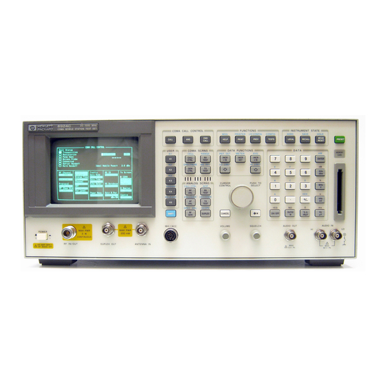
HP 8924C/E CDMA Mobile Station Test Set
RF IN/OUT
POWER
OFF
ON
N:\mkt\MANUALS\HP8924C\ALR\front.fb
Assembly Level Repair
HP 8924C: Firmware Version A.02.17 and above
HP 8924E: Firmware Version A.01.00 and above
CALL
USER
k1'
k1
k2'
k2
k3'
k3
ASSIGN
k4
RELEASE
k5
SHIFT
MIC/ACC
ANT IN
DUPLEX OUT
!
!
MAX PWR
MAX PWR
6 W
200 mW
HP P/N 08924-90061
Printed in U.S.A.
November 1998
CDMA CALL CONTROL
FUNCTIONS
MSG
PRINTER
I/O CONFIG
END
ANS
HELP
PRINT
PREV
CALL
CDMA SCRNS
DATA FUNCTIONS
CELL
RANGE
REF SET
METER
AVG
CALL
RX
INCR
INCR
INCR X10
CTRL
TEST
: 10
SET
SPECTRUM
MSRPT
LO LIMIT
HI LIMIT
GEN
TX
CTRL
TEST
CURSOR
PUSH TO
CONTROL
SELECT
CDMA SCRNS
ENCODER
DECODER
RF
RX
ANL
TEST
ACP
AF
TX
ANL
TEST
SPEC ANL
SCOPE
RF
DUPLEX
CANCEL
GEN
VOLUME
SQUELCH
Rev. A
INSTRUMENT STATE
CONFIG
ADRS
SAVE
HOLD
MEAS
TESTS
LOCAL
RECALL
PRESET
RESET
MEMOR
Y CARD
DATA
7
8
9
ENTER
dB
GHz
4
5
6
dBm
%
MHz
1
2
3
V
s
+ _
kHz
0
mV
Ω
YES
NO
ms
ppm
%
Hz
ON/OFF
µV
W
dBµV
AUDIO OUT
AUDIO IN
HI
LO
MAX
MAX
!
!
12 v Pk
42 v Pk
1
Advertisement
Table of Contents

Related Manuals for HP 8924C


Summary of Contents for HP 8924C
- Page 1 HP 8924C/E CDMA Mobile Station Test Set Assembly Level Repair HP 8924C: Firmware Version A.02.17 and above HP 8924E: Firmware Version A.01.00 and above CDMA CALL CONTROL FUNCTIONS INSTRUMENT STATE PRINTER I/O CONFIG CONFIG ADRS SAVE HOLD MEAS CALL HELP...
- Page 2 Copyright © Hewlett-Packard Company 1998 Notice Information contained in this document is subject to change without notice. All Rights Reserved. Reproduction, adaptation, or translation without prior written permission is prohibited, except as allowed under the copyright laws. This material may be reproduced by or for the U.S. Government pursuant to the Copyright License under the clause at DFARS 52.227-7013 (APR 1988).
- Page 3 Manufacturer’s Declaration This statement is provided to comply with the requirements of the German Sound Emission Directive, from 18 January 1991. This product has a sound pressure emission (at the operator position) < 70 dB(A). Sound Pressure Lp < 70 dB(A). •...
- Page 4 Safety GENERAL Considerations This product and related documentation must be reviewed for familiarization with safety markings and instructions before operation. This product has been designed and tested in accordance with IEC Publication 1010, "Safety Requirements for Electronic Measuring Apparatus," and has been supplied in a safe condition.
- Page 5 Safety Considerations for this Instrument WARNING This product is a Safety Class I instrument (provided with a protective earthing ground incorporated in the power cord). The mains plug shall only be inserted in a socket outlet provided with a protective earth contact. Any interruption of the protective conductor inside or outside of the product is likely to make the product dangerous.
- Page 6 CAUTION: Always use the three-prong ac power cord supplied with this product. Failure to ensure adequate earth grounding by not using this cord may cause product damage. This product is designed for use in Installation Category II and Pollution Degree 2 per IEC 1010 and IEC 664 respectively.
- Page 7 For warranty service or repair, this product must be returned to a service facility designated by HP. Buyer shall prepay shipping charges to HP and HP shall pay shipping charges, duties, and taxes for products returned to HP from another country.
- Page 8 Liberty Lake, Washington 99019-9599 declares that the product CDMA Mobile Station Test Set Product Name: Model Number: HP 8924C Product Options: This declaration covers all options of the above product. conforms to the following Product specifications: Safety: IEC 1010-1:1990+A1 / EN 61010-1:1993 CAN/CSA-C22.2 No.
- Page 9 Liberty Lake, Washington 99019-9599 declares that the product CDMA Mobile Station Test Set Product Name: Model Number: HP 8924E Product Options: This declaration covers all options of the above product. conforms to the following Product specifications: Safety: IEC 1010-1:1990+A1 / EN 61010-1:1993 CAN/CSA-C22.2 No.
- Page 10 If you have used the manuals and still have application questions, contact your local HP Sales Representative. Repair assistance is available for the HP 8924C/E CDMA Mobile Test Set from the factory by phone and e-mail. Internal Hewlett-Packard users can contact the factory through HPDesk or cc:Mail©...
- Page 11 Regional Sales and Service Offices United States of America United States of America U.S. Instrument Support Center Customer Information Center For Test & Measurement Equipment For Assistance On All HP Products. Repair & Calibration. Hewlett-Packard Company Hewlett-Packard Company Tel: (800) 752-0900 Englewood, Colorado 80112...
- Page 12 Table 2 Regional Sales and Service Offices (Continued) Canada Latin America United Kingdom Service Center Hewlett-Packard Company Sales and Service Hewlett-Packard Ltd. LAHQ Mexico City Hewlett-Packard Ltd. 11120 178 Street Col. Lomas de Virreyes Cain Road Edmonton, Alberta T5S 1P2 11000 Mexico D.F.
- Page 13 Power Cables Plug Descriptions HP Part # Plug Type Cable Descriptions male/female (cable &plug) Straight/Straight 8120-1689 79 inches, mint gray Straight/90° 8120-1692 79 inches, mint gray Earth Ground Line Neutral Used in the following locations Afghanistan, Albania, Algeria, Angola, Armenia,Austria, Azerbaijan, Azores...
- Page 14 Plug Descriptions HP Part # Plug Type Cable Descriptions male/female (cable & plug) Straight/Straight 8120-0698 90 inches, black Earth Ground Line Line Used in the following locations Peru Plug Descriptions HP Part # Plug Type Cable Descriptions male/female (cable & plug)
- Page 15 Plug Descriptions HP Part # Plug Type Cable Descriptions male/female (cable & plug) Straight/Straight 8120-1378 90 inches, jade gray 125V Straight/90° 8120-1521 90 inches, jade gray Straight/Straight 8120-1751 90 inches, jade gray Earth Ground Neutral Line Used in the following locations...
- Page 16 Plug Descriptions HP Part # Plug Type Cable Descriptions male/female (cable & plug) Straight/Straight 8120-4753 90 inches, dark JIS C 8303, 100 V Straight/90° 8120-4754 gray 90 inches, dark gray Earth Ground Neutral Line Used in the following locations Japan...
- Page 17 Plug Descriptions HP Part # Plug Type Cable Descriptions male/female (cable & plug) Straight/Straight 8120-4211 79 inches, mint gray Straight/90° 8120-4600 79 inches, mint gray Earth Ground Line Neutral Used in the following locations Botswana India Lesotho Malawi South-West Africa (Namibia), Swaziland...
- Page 18 Plug HP Part # Plug Type (Male) Descriptions Cable Descriptions (cable & plug) male/female 90°/Straight 8120-1351 90 inches, mint gray 90°/90° 8120-1703 90 inches, mint gray Earth Ground Line Neutral Used in the following locations Bahrain, British Indian Ocean Terr., Brunei...
- Page 19 Plug Descriptions HP Part # Plug Type Cable Descriptions male/female (cable & plug) Straight/Straight 8120-1369 79 inches, gray Straight/90° 8120-0696 80 inches, gray Earth Ground Line Neutral Used in the following locations Argentina, Australia China (People’s Republic) New Zealand Papua New Guinea...
- Page 20 ATTENTION Static Sensitive Devices This instrument was constructed in an ESD (electro-static discharge) protected environment. This is because most of the semi conductor devices used in this instrument are susceptible to damage by static discharge. Depending on the magnitude of the charge, device substrates can be punctured or destroyed by contact or mere proximity of a static charge.
- Page 21 A general description of what the Test Set does is included. Theory of Operation, troubleshooting, repairing, calibrating, and verifying instrument performance are discussed. Additional HP support information is provided. Chapter 2, Troubleshooting The process for isolating a failure to the faulty assembly is discussed, including how to use the automated diagnostic routines.
- Page 22 Chapter 10, Diagnostic Descriptions Test Set’s automated diagnostics are described. The descriptions help you understand what has been checked by the diagnostics in case they cannot identify a probable failure and you must troubleshoot further. Appendix A, Error Messages N:\mkt\MANUALS\HP8924C\ALR\front.fb...
- Page 23 Contents 1 Introduction Test Set Description 56 Theory of Operation 58 Troubleshooting Strategy 65 Repair Process 66 Calibration and Performance Verification 67 HP 8924C/E Support Contacts 68 Hardware and Firmware Enhancements 69 N:\mkt\MANUALS\HP8924C\ALR\8924CE.TOC...
- Page 24 Contents 2 Troubleshooting How to Troubleshoot the Test Set 72 Step 1- Run the Power-up Diagnostics 74 Step 2- Run the Functional Diagnostics 75 Step 3 - Verify Test Set Functions 78 More About Step 1- Run the Power-Up Diagnostic 79 More About Step 2- Run the Functional Diagnostics 81 USER Keys 81 Frequently Encountered Error Messages 81...
- Page 25 Contents 3 Repair Before You Start 102 Recommended Torque 102 Tools 102 Ordering Replacement Parts 102 Downloading Calibration Data 103 Locating Assemblies 104 Disassembly and Replacement Procedures 105 Removing the External Covers 105 Removing the Front Panel Assembly: A1, A2, A3, A4, and A5 107 Replacing Keyboard Filter Assembly (A2) 111 Front Panel Disassembly 113 Removing Power Supply (A23) 122...
-
Page 26: Table Of Contents
Contents 4 Periodic Adjustments Introduction 138 Manual and Automated Adjustments 139 Calibration Equipment 140 10 MHz Oven Timebase Adjustment 140 Zeroing the DC_FM, DC Current, TX Power, and CDMA Power Functions 141 Running the Periodic Calibration Programs 142 Write-Protected Calibration Data 143 PER_CAL3 Routines 144 CDMA_CAL Routines 147 PCB_CAL Routine 148... - Page 27 Contents 5 HP 8924C Performance Verification Verifying Performance 150 Test Set Operation 150 Equipment 150 Test Equipment Operation 151 RF Gen FM Distortion Performance Test 1 152 Description 152 Setup 152 Procedure 153 RF Gen FM Accuracy Performance Test 2 154...
- Page 28 Contents Description 163 Setup 163 Procedure 164 RF Gen RF IN/OUT Level Accuracy Performance Test 7 165 Description 165 Setup 165 Procedure 166 RF Gen Harmonics Spectral Purity Performance Test 8 167 Description 167 Setup 167 Procedure 168 RF Gen Spurious Spectral Purity Performance Test 9 169 Description 169 Setup 169...
- Page 29 Contents AF Gen Frequency Accuracy Performance Test 13 177 Description 177 Setup 177 Procedure 178 AF Analyzer AC Voltage Accuracy Performance Test 14 179 Description 179 Setup 179 Procedure 180 AF Analyzer Residual Noise Performance Test 15 181 Description 181 Setup 181 Procedure 182 AF Analyzer Distortion, SINAD, and SNR Accuracy...
- Page 30 Contents Description 189 Setup 189 Procedure 190 Oscilloscope Performance Test 20 191 Description 191 Setup 191 Procedure 192 RF Analyzer Level Accuracy Performance Test 21 193 Description 193 Calibration Setup 193 Calibration Procedure 194 Measurement Setup 195 Measurement Procedure 195 RF Analyzer FM Accuracy Performance Test 22 197 Description 197...
- Page 31 Contents Description 207 Setup 207 Procedure 208 Spectrum Analyzer Image Rejection Performance Test 26 209 Description 209 Setup 209 Image Rejection Procedure 210 Residual Response Procedure 211 CDMA Generator RF In/Out Amplitude Level Accuracy Performance Test 27 212 Description 212 Calibration Setup 212 Procedure 213 CDMA Generator Duplex Out Amplitude Level Accuracy...
- Page 32 Contents CDMA Analyzer Calibrated Tuned Channel Power Level Accuracy Performance Test 31 224 Description 224 Calibration Setup 224 Calibration Procedure 225 Measurement Setup 226 Measurement Procedure 227 CDMA Analyzer Relative Tuned Channel Power Level Accuracy Performance Test 32 228 Description 228 Setup 228 Procedure 229 N:\mkt\MANUALS\HP8924C\ALR\8924CE.TOC...
- Page 33 Contents 6 HP 8924E Performance Verification Verifying Performance 232 Test Set Operation 232 Equipment 232 Test Equipment Operation 233 RF Gen FM Distortion Performance Test 1 234 Description 234 Setup 234 Procedure 235 RF Gen FM Accuracy Performance Test 2 236...
- Page 34 Contents Description 244 Setup 244 Procedure 245 RF Gen RF IN/OUT Level Accuracy Performance Test 7 246 Description 246 Setup 246 Procedure 247 RF Gen Harmonics Spectral Purity Performance Test 8 248 Description 248 Setup 248 Procedure 249 RF Gen Spurious Spectral Purity Performance Test 9 250 Description 250 Setup 250...
- Page 35 Contents AF Analyzer AC Voltage Accuracy Performance Test 14 258 Description 258 Setup 258 Procedure 259 AF Analyzer Residual Noise Performance Test 15 260 Description 260 Setup 260 Procedure 261 AF Analyzer Distortion, SINAD, and SNR Accuracy Performance Test 16 262 Description 262 Setup 262 Procedure 263...
- Page 36 Contents Description 270 Setup 270 Procedure 271 RF Analyzer Level Accuracy Performance Test 21 272 Description 272 Calibration Setup 272 Calibration Procedure 273 Measurement Setup 274 Measurement Procedure 274 RF Analyzer FM Accuracy Performance Test 22 276 Description 276 Setup 277 Procedure 278 RF Analyzer FM Distortion Performance Test 23 279...
- Page 37 Contents Description 287 Setup 287 Image Rejection Procedure 288 Residual Response Procedure 288 CDMA Generator RF In/Out Amplitude Level Accuracy Performance Test 27 289 Description 289 Calibration Setup 289 Procedure 290 CDMA Generator Duplex Out Amplitude Level Accuracy Performance Test 28 291 Description 291 Setup 291 Procedure 292...
- Page 38 Contents CDMA Analyzer Relative Tuned Channel Power Level Accuracy Performance Test 32 302 Description 302 Setup 302 Procedure 303 N:\mkt\MANUALS\HP8924C\ALR\8924CE.TOC...
- Page 39 Contents 7 HP 8924C Performance Test Records HP 8924C RF Communications Test Set 306 RF Gen FM Distortion Performance Test 1 307 RF Gen FM Accuracy Performance Test 2 309 RF Gen FM Flatness Performance Test 3 311 RF Gen Residual FM...
- Page 40 Contents AF Gen Frequency Accuracy Performance Test 13 334 AF Analyzer AC Voltage Accuracy Performance Test 14 335 AF Analyzer Residual Noise Performance Test 15 336 AF Analyzer Distortion, SINAD and SNR Accuracy Performance Test 16 337 AF Analyzer DC Level Accuracy Performance Test 17 339 AF Analyzer Frequency Accuracy to 100 kHz Performance Test 18 340...
- Page 41 Contents Spectrum Analyzer Image Rejection Performance Test 26 348 CDMA Generator RF In/Out Amplitude Level Accuracy Performance Test 27 350 CDMA Generator Duplex Out Amplitude Level Accuracy Performance Test 28 351 CDMA Generator Adjacent Channel Spectral Purity Performance Test 29 352 CDMA Analyzer Average Power Level Accuracy Performance Test 30 353 CDMA Analyzer Calibrated Tuned Channel Power Level Accuracy...
- Page 42 Contents 8 HP 8924E Performance Test Records HP 8924E RF Communications Test Set 358 RF Gen FM Distortion Performance Test 1 359 RF Gen FM Accuracy Performance Test 2 361 RF Gen FM Flatness Performance Test 3 363 RF Gen Residual FM...
- Page 43 Contents AF Analyzer AC Voltage Accuracy Performance Test 14 384 AF Analyzer Residual Noise Performance Test 15 385 AF Analyzer Distortion, SINAD and SNR Accuracy Performance Test 16 386 AF Analyzer DC Level Accuracy Performance Test 17 388 AF Analyzer Frequency Accuracy to 100 kHz Performance Test 18 389 AF Analyzer Frequency Accuracy at 400 kHz Performance Test 19 390...
- Page 44 Contents CDMA Generator RF In/Out Amplitude Level Accuracy Performance Test 27 399 CDMA Generator Duplex Out Amplitude Level Accuracy Performance Test 28 400 CDMA Generator Adjacent Channel Spectral Purity Performance Test 29 401 CDMA Analyzer Average Power Level Accuracy Performance Test 30 402 CDMA Analyzer Calibrated Tuned Channel Power Level Accuracy Performance Test 31 403 CDMA Analyzer Relative Tuned Channel Power Level Accuracy...
- Page 45 FM Measurement 413 Spectrum Analyzer Specifications (HP 8924E: Option 102 required) 414 General 414 Tracking Generator 415 Adjacent Channel Power Specifications (HP 8924C ONLY) 416 Relative Measurements 416 Absolute Measurements (HP 8924C ONLY) 417 AF Analyzer Specifications 418 Frequency Measurement 418...
- Page 46 CDMA Average Power Measurement 434 CDMA Tuned Channel Power Measurement 436 CDMA Modulation Measurement 437 CDMA Frame Error Rate Measurement 438 CDMA Reverse Channel Spectrum Display (HP 8924E: Option 102 required) 439 CDMA Triggers 440 General Specifications 441 Remote Programming Specifications 441...
- Page 47 Contents 10 Service Screen Troubleshooting with the Service Screen 450 How to Access the Service Screen 450 Field Names and Descriptions 451 N:\mkt\MANUALS\HP8924C\ALR\8924CE.TOC...
- Page 48 Contents 11 Block Diagrams Introduction 456 I/O Specifications and Switch Information 456 Section Details 457 RF Input/Output Section 457 Spectrum Analysis (Optional on 8924E) 460 Audio Analyzer Section 462 Oscilloscope Functions 462 RF Generator Section 465 Audio Generator Section 468 Assembly Details 470 Assembly Level Block Diagrams 470 N:\mkt\MANUALS\HP8924C\ALR\8924CE.TOC...
- Page 49 Contents 12 HP 8924C Replaceable Parts General Information about Replaceable Parts 524 Self-Support Programs 524 Direct Parts Ordering 524 Assembly Replacements 524 Replaceable Parts Listing 525 N:\mkt\MANUALS\HP8924C\ALR\8924CE.TOC...
- Page 50 Contents 13 HP 8924E Replaceable Parts General Information about Replaceable Parts 532 Self-Support Programs 532 Direct Parts Ordering 532 Assembly Replacements 532 Replaceable Parts Listing 533 N:\mkt\MANUALS\HP8924C\ALR\8924CE.TOC...
- Page 51 Contents 14 Diagnostics Descriptions Description Of Self-Test Diagnostic 541 Introduction 541 Reading Self-Test Diagnostic Failure Codes From the Front Panel or HP-IB 541 Reading LED Codes 543 Description Of Audio Diagnostics (AFDIAGS3) 548 Introduction 548 Audio Frequency Generators 1 and 2 548...
- Page 52 Contents A Error Messages N:\mkt\MANUALS\HP8924C\ALR\8924CE.TOC...
- Page 53 Contents Index 633 N:\mkt\MANUALS\HP8924C\ALR\8924CE.TOC...
- Page 54 Contents N:\mkt\MANUALS\HP8924C\ALR\8924CE.TOC...
- Page 55 Introduction This manual explains how to repair and calibrate the HP 8924C/E CDMA Mobile Station Test Set; called “the Test Set” throughout this manual. N:\mkt\MANUALS\HP8924C\ALR\intro.fb...
- Page 56 (such as making a call to a CDMA mobile phone). An HP Instrument BASIC (IBASIC) computer is also built into the Test Set to allow automated operation without using an external controller. This computer also has the ability to be a system controller to other test system instruments.
- Page 57 Chapter 1, Introduction Test Set Description Front & Rear Panel Connections HP 68020 Host Processor * optional for HP 8924E CDMA INSTRU DATA CALL CONTROL CDMA CALL CONTROL FUNCTIONS INSTRUMENT STATE CDMA GENERATOR CONTROL PRINTER I/O CONFIG CONFIG ADRS SAVE...
- Page 58 Test Set. The host is also in constant communication with several other microprocessors located in assemblies throughout the Test Set. Communications to the HP-IB, Serial, and Parallel ports are through the Control Interface (A33) assembly to the host processor.
- Page 59 Chapter 1, Introduction Theory of Operation Instrument Most of the Test Set’s internal oscillators and counters are phase-locked to the Frequency signal input from the rear-panel REF INPUT port. This signal is usually the output of the 10 MHz Oven Oscillator (A38) assembly, also available on the rear-panel. References The Reference Assembly (A27) is internally connected to the CDMA Reference (A29), which is connected to the external reference.
- Page 60 FM signals are downconverted to a 700 kHz IF before demodulation. The demodulated signal is routed to the Audio Analyzer 1 (A35) (HP 8924E: FM assembly for audio frequency filtering. This assembly is also connected to the only) front-panel AUDIO IN connector for direct audio measurements.
- Page 61 The rear-panel AUD MONITOR OUTPUT connector for external use of the demodulated signal. • The front-panel VOLUME control and internal Speaker to listen to the demodulated signal. HP 8924E: FM Demod Only Receiver Assembly (A30) Audio Analyzer 1 Assembly (A3 15 kHz 114.3 MHz 10.7 MHz...
- Page 62 Chapter 1, Introduction Theory of Operation The Receive DSP assemblies analyze the 3.6864 MHz signal to make IQ modulation measurements, such as Rho, Timing Accuracy, Carrier Feedthrough, and Phase Error. To Spectrum Analyzer (A32) LO/IF Demod Assembly (A31) 114.3MHz IF Cell Site Digital Assemblies from Receiver Protocol...
- Page 63 Chapter 1, Introduction Theory of Operation • Controls the signal level out of the assembly using an Automatic Level Control (ALC) loop. The signal out of the Output assembly is now at the user-selected frequency, and contains any modulation that was selected (AM, FM, or CDMA), or is a continuous wave (CW) signal.
- Page 64 Chapter 1, Introduction Theory of Operation RF and DUPLEX The Input assembly receives the signal from the output assembly and routes it to Outputs the selected output port: RF IN/OUT or DUPLEX OUT. The signal first goes to a variable attenuator for level control. If the DUPLEX OUT port is selected, the signal then goes directly to that port without additional attenuation.
- Page 65 Chapter 1, Introduction Troubleshooting Strategy Troubleshooting Strategy You can repair the Test Set yourself or send it to your local Hewlett-Packard Customer Service Center. Before starting a repair, you should become familiar with basic Test Set operation using the User’s Guide. Troubleshooting relies on built-in diagnostics.
- Page 66 Repairing the Test Set consists of: • Identifying the faulty assembly (see chapter 2, "Troubleshooting") • Ordering a replacement assembly (see chapter 12, "HP 8924C Replaceable Parts" chapter 13, "HP 8924E Replaceable Parts") • Replacing the faulty assembly (see chapter 3, "Repair") •...
- Page 67 Chapter 1, Introduction Calibration and Performance Verification Calibration and Performance Verification The Test Set periodically requires some maintenance to verify that it meets its published specifications. Periodic Adjustments (calibration) consists of running several built-in calibration programs, and should be performed every year. An external frequency counter and dc voltmeter are required.
- Page 68 If you have used the manuals and still have application questions, contact your local HP Sales Representative. Repair assistance is available for the HP 8924C/E CDMA Mobile Test Set from the factory by phone and e-mail. Internal Hewlett-Packard users can contact the factory through HPDesk or cc:Mail©...
- Page 69 Chapter 1, Introduction Hardware and Firmware Enhancements Hardware and Firmware Enhancements The hardware and firmware of the Test Set are enhanced on a continuous basis. If an assembly is replaced, it is recommended that the firmware be upgraded at the same time.
- Page 70 Chapter 1, Introduction Hardware and Firmware Enhancements N:\mkt\MANUALS\HP8924C\ALR\intro.fb...
- Page 71 Troubleshooting This chapter tells how to isolate a problem to the defective assembly. Troubleshooting is centered around the built-in diagnostics. If diagnostics can’t identify the faulty assembly, supplementary information in the form of detailed Block Diagrams ( ), Diagnostics Descriptions ( ), and chapter 11 chapter 14...
- Page 72 Chapter 2, Troubleshooting How to Troubleshoot the Test Set How to Troubleshoot the Test Set This section explains the steps for troubleshooting the Test Set. Document the result of each step in case you need to contact Hewlett-Packard for service assistance.
- Page 73 Chapter 2, Troubleshooting How to Troubleshoot the Test Set If the Test Set powers-up normally, duplicate the application where the problem exists to determine if the Test Set is not being used properly or is being used beyond its warranted specifications Does an image appear Refer to figure 8, "Troubleshooting a Blank Display,"...
- Page 74 Chapter 2, Troubleshooting How to Troubleshoot the Test Set Step 1- Run the Power-up Diagnostics To start troubleshooting: • Turn on the Test Set to automatically run the power-up diagnostics. • After power-up, the top line of the Test Set’s display should show copyright information and the firmware revision code.
- Page 75 Chapter 2, Troubleshooting How to Troubleshoot the Test Set Step 2- Run the Functional Diagnostics The Functional Diagnostics make measurements that test many of the circuits. There are four Functional Diagnostics. The first three (Audio, RF, and CDMA diagnostics) can be run in a loop mode after an initial setup. This is useful for trapping intermittent failures.
- Page 76 14. Set the Printer Port: for the rear-panel connector your printer is connected to. If an HP-IB printer is used, you need to enter the printer’s two-digit bus address when the Printer Adrs field appears (Example; enter 01 for bus address 701). Also, press the SHIFT key, then the PREV key to access the I\O CONFIGURE screen, and set the Mode field to Control.
- Page 77 Chapter 2, Troubleshooting How to Troubleshoot the Test Set USER Figure 7 Running the Functional Diagnostics N:\mkt\MANUALS\HP8924C\ALR\trouble.fb...
- Page 78 Step 3 - Verify Test Set Functions Suggestions: • Run all or a selected group of the Performance Tests. See chapter 5, "HP 8924C Performance Verification" .chapter 6, "HP 8924E Performance Verification" • Run selected Periodic Calibration procedures. See chapter 4, "Periodic Adjustments". •...
- Page 79 If an error message appears and remains in the center of the display, or if the Test Set does not respond to any keys or HP-IB commands, the Test Set may be configured to power-up to a custom procedure (rather than the default screen) and that procedure may have errors.
- Page 80 Chapter 2, Troubleshooting More About Step 1- Run the Power-Up Diagnostic Power up with cover on. Look through the rear panel for a lit LED on the Power Supply. If the Fan runs? LED is not lit, the Power Supply is faulty or is not getting mains power.
- Page 81 TESTS (Printer Setup) screen are set wrong for your printer. Also, check that the printer’s power is on and that it is correctly cabled. For HP-IB printers make sure the printer is correctly addressed. If a serial printer is used, you may have to change the serial communication settings on the I/O CONFIGURE screen (press SHIFT then PREV to get to this screen).
- Page 82 Chapter 2, Troubleshooting More About Step 1- Run the Power-Up Diagnostic Timeouts Certain failures may cause a frequency or voltage reading to timeout, that is, the time required for the measurement will be unreasonably long. If a timeout occurs, measurement execution will stop and an error message will be displayed. •...
- Page 83 Chapter 2, Troubleshooting More About Step 1- Run the Power-Up Diagnostic RF Diagnostics (RFDIAGS3) This program tests the RF functions of the following assemblies: • A19 Receiver 1st Mixer • A26 Output • A24 Signal Generator Synthesizer • A27 Reference •...
- Page 84 Chapter 2, Troubleshooting More About Step 1- Run the Power-Up Diagnostic Miscellaneous Diagnostics (MSDIAGS3) This program verifies the following: • The ability of the A27 Reference to detect the presence of the A29 CDMA Reference signal and its ability to lock to that signal. •...
- Page 85 Chapter 2, Troubleshooting More About Step 1- Run the Power-Up Diagnostic Troubleshooting Aids Refer to following table to determine which Diagnostic Tests, Performance Tests, and Periodic Self Calibration Adjustments apply to an assembly. Downloading calibration data is discussed in chapter 3, "Repair," on page 101 Table 4 Relating Assemblies To Troubleshooting Aids Troubleshooting with...
- Page 86 Chapter 2, Troubleshooting More About Step 1- Run the Power-Up Diagnostic Table 4 Relating Assemblies To Troubleshooting Aids (Continued) Troubleshooting with Cal- Diagnostics (Chapter 2) Periodic Performance Data Assembly Adjustments Ref. Verification Needed Name Power- Des. (Chapter 5) After Up Self (Chapter 4) Repl ? Tests...
- Page 87 Chapter 2, Troubleshooting More About Step 1- Run the Power-Up Diagnostic Table 4 Relating Assemblies To Troubleshooting Aids (Continued) Troubleshooting with Cal- Diagnostics (Chapter 2) Periodic Performance Data Assembly Adjustments Ref. Verification Needed Name Power- Des. (Chapter 5) After Up Self (Chapter 4) Repl ? Tests...
- Page 88 Besides checking the assemblies marked X, the power-up self test checks the serial data lines which the con- troller uses to send control signals to and receive status signals from the RF and AF assemblies. HP 8924E: Required if Spectrum Analyzer is installed. Measurement checked indirectly by all diagnostics.
- Page 89 Chapter 2, Troubleshooting More about Step 4 - Verify Test Set Functioning More about Step 4 - Verify Test Set Functioning See "Locating the Out-Of-Lock (OOL) Indicators" on page 89 Out-of-lock (OOL) LEDs light when a phase-locked loop inside an assembly is failing. The Signal Generator Synthesizer (A24), Receiver Synthesizer (A28), CDMA Reference (A29), and LO/IF Demod (A31) assemblies have these LEDs mounted close to the top of the modules.
- Page 90 Chapter 2, Troubleshooting More about Step 4 - Verify Test Set Functioning Isolating Out-of-Lock Conditions If more than one OOL indicator is lit. CDMA Reference and LO/IF Demod: If the CDMA Reference is unlocked, the LO/IF Demod assembly will be unlocked, since its reference comes from the CDMA Reference.
- Page 91 Chapter 2, Troubleshooting More about Step 4 - Verify Test Set Functioning CDMA Reference (A29) Unlocked 1. Verify that the rear-panel 10 MHz Oven Out signal is at 10 MHz, and at a level of 0 dBm ±3 dB into 50 Ω. 2.
- Page 92 Chapter 2, Troubleshooting More about Step 4 - Verify Test Set Functioning LO/IF Demod (A31) Unlocked This assembly is phase-locked to a signal from the CDMA Reference. If the CDMA Reference is out-of-lock, troubleshoot that assembly first before proceeding. 1. Turn the Test Set off. 2.
- Page 93 Chapter 2, Troubleshooting More about Step 4 - Verify Test Set Functioning Receiver Synthesizer (A28) Unlocked 1. Turn the Test Set off. 2. Remove the rear assemblies cover (two assembly pry tools are removed in the process). 3. Use the pry tools to remove the Receiver Synthesizer assembly. 4.
- Page 94 A28 Receiver Synthesizer • A32 Spectrum Analyzer (optional in some Test Sets) • A37 Measurement • A33 HP-IB/RS-232/Current Sense • A5 Input • A4 Attenuator Of these assemblies the A5 Input is the least likely candidate for a successful assembly swap.
- Page 95 Chapter 2, Troubleshooting More about Step 4 - Verify Test Set Functioning Some assemblies require that a periodic calibration procedure be run. These are: • A36 Audio Analyzer 2 (variable-frequency notch filter null if present) • A35 Audio Analyzer 1 (DC offset) •...
- Page 96 Chapter 2, Troubleshooting Further Isolating RF Failures Further Isolating RF Failures Isolating failures in the RF assemblies of the Test Set can be difficult. One problem is that the RF Diagnostics sometimes use the built-in RF analyzer to test the built-in RF source, and vice versa. This is necessary to make the diagnostics self-contained, that is, they run without external equipment.
- Page 97 Chapter 2, Troubleshooting Further Isolating RF Failures Isolating Input and Output Failures If all RF diagnostic tests pass, there could still be a problem with the input and output paths (including reverse-power and overpower protection). Run the Miscellaneous Diagnostics test titled RF Input Output Test. A failure indicates that the input section or front-panel connection is faulty.
- Page 98 Chapter 2, Troubleshooting Further Isolating RF Failures To isolate an RF Analyzer problem: • On the Test Set: • Press PRESET. • Press the SHIFT key, then press the TESTS key to access the CONFIGURE screen. Set the RF Display field to Freq. Set the RF Offset field to Off.
- Page 99 Chapter 2, Troubleshooting Further Isolating RF Failures Refer to the block diagrams in . The down chapter 11, "Block Diagrams" conversion frequencies for the three input frequencies are shown in the following table. Table 5 Deriving Output Frequencies Input First LO IF From Frequency Frequency...
- Page 100 Chapter 2, Troubleshooting Further Isolating RF Failures Isolating the RF Source The RF Generator function uses the following assemblies. Refer to the block diagrams in chapter 11, "Block Diagrams" • A27 Reference and A29 CDMA Reference • A24 Signal Generator Synthesizer •...
- Page 101 Repair This chapter contains information needed to remove and replace assemblies in the Test Set. Some assemblies require calibration data to be downloaded when replaced ( see "Downloading Calibration Data" on page 103 N:\mkt\MANUALS\HP8924C\ALR\repair.fb...
- Page 102 3/16-inch socket wrench • 1/4 -inch open-end wrench • 5/16-inch open-end wrench Ordering Replacement Parts Lists of replaceable parts and part ordering information are provided in - chapter 12, "HP 8924C Replaceable Parts" see chapter 13, "HP 8924E Replaceable Parts" N:\mkt\MANUALS\HP8924C\ALR\repair.fb...
- Page 103 Chapter 3, Repair Downloading Calibration Data Downloading Calibration Data Most assemblies in the Test Set require calibration data. To ensure that the Test Set remains calibrated after an assembly is replaced, new calibration data must be downloaded. When required, calibration data is provided on a PCMCIA memory card that is included with the replacement assembly.
- Page 104 Chapter 3, Repair Locating Assemblies Locating Assemblies A10 (Future Option) (Future Option) Figure 10 Locating Assemblies N:\mkt\MANUALS\HP8924C\ALR\repair.fb...
- Page 105 Chapter 3, Repair Disassembly and Replacement Procedures Disassembly and Replacement Procedures Removing the External Covers MP 51 MP 15 (Qty 14) (9 in.lbs) MP 52 (Qty 4) MP 53 (Qty 2) MP 16 (Qty 4) MP 49 (Qty 2) (21 in.lbs) 6d50.gif MP 15 (Qty 8) (21 in.lbs)
- Page 106 Chapter 3, Repair Disassembly and Replacement Procedures MP 46 MP 44 6d30.gif Figure 12 Removing the Instrument Cover N:\mkt\MANUALS\HP8924C\ALR\repair.fb...
- Page 107 Chapter 3, Repair Disassembly and Replacement Procedures Removing the Front Panel Assembly: A1, A2, A3, A4, and A5 The front panel assembly consists of the Keyboard (A1), Keyboard Filters (A2), CRT (A3) Attenuator (A4), and the Input assembly (A5). The entire front-panel assembly must be removed before any of the sub-assemblies can be removed.
- Page 108 Chapter 3, Repair Disassembly and Replacement Procedures W 10 (9 in.lbs) TO REMOVE FRONT PANEL LOOSEN SCREWS DISCONNECT W3, W 7 AND W10. ON OUTSIDE TO REMOVE MIXER. TO REMOVE A19 DISCONNECT W 10, W 3, W 21 AND W22. W 21 NEW A19 7e20a.gif...
- Page 109 Chapter 3, Repair Disassembly and Replacement Procedures MP 30 (Qty 4) (21 in.lbs) A 41 7d80.gif MP 9 MP 10 DISCONNECT MP20-22, W1, W5, AND W6 FROM MOTHERBOARD (W60). W 27 W 28 W 29 7d40.gif Figure 15 Front Panel Assembly Connections N:\mkt\MANUALS\HP8924C\ALR\repair.fb...
- Page 110 Chapter 3, Repair Disassembly and Replacement Procedures DISCONNECT KEYBOARD HARNESS KEYBOARD HARNESS 7d30.gif Figure 16 Keyboard N:\mkt\MANUALS\HP8924C\ALR\repair.fb...
- Page 111 Chapter 3, Repair Disassembly and Replacement Procedures Replacing Keyboard Filter Assembly (A2) MP 31 (Qty 25) (21 in.lbs) MP 54 MP 45 6c60.gif Figure 17 Keyboard Cable Connections N:\mkt\MANUALS\HP8924C\ALR\repair.fb...
- Page 112 Chapter 3, Repair Disassembly and Replacement Procedures W 20 7c50.gif MP 48 (Qty 2) MP 43 (Qty 2) (9 in.lbs) 7c40.gif Figure 18 Keyboard Filter Replacement (A2) N:\mkt\MANUALS\HP8924C\ALR\repair.fb...
- Page 113 Chapter 3, Repair Disassembly and Replacement Procedures Front Panel Disassembly MP 35 (Qty 2) (21 in.lbs) DICONNECT (6 in.lbs) 5d30.gif MP 39 (21 in.lbs) DISCONNECT DISCONNECT MP 35(Qty 2) (21 in.lbs) DICONNECT W 23 5d20.gif (6 in.lbs) Figure 19 Disconnecting A4 and A5 From the Front Frame N:\mkt\MANUALS\HP8924C\ALR\repair.fb...
- Page 114 Chapter 3, Repair Disassembly and Replacement Procedures WHEN INSTALLING NEW A5 INTO FRONT PANEL, TORQUE LOCKING NUTS (MP10) BEFORE INSTALLING SCREWS MP35 AND MP39. MP 10 (Qty 2) (21 in.lbs) 5d50.gif 5d50.gif Figure 20 Removing A5 N:\mkt\MANUALS\HP8924C\ALR\repair.fb...
- Page 115 Chapter 3, Repair Disassembly and Replacement Procedures A5W1 (9 in.lbs) A5W1 CABLE CLAMPS MP 20 MP 22 MP 21 5d40.gif Figure 21 Cable Routing to the Front Frame N:\mkt\MANUALS\HP8924C\ALR\repair.fb...
- Page 116 Chapter 3, Repair Disassembly and Replacement Procedures A5W1 (9 in.lbs) A5W1 CABLE CLAMPS MP 20 MP 22 MP 21 5d40.gif Figure 22 Cable Routing to the Front Frame M P 41 SWING OUT PULL OUT MP 41 PRY UP 5d10.gif Figure 23 Removing the Display Bezel N:\mkt\MANUALS\HP8924C\ALR\repair.fb...
- Page 117 Chapter 3, Repair Disassembly and Replacement Procedures MP 40 MP 41 MP 35 (Qty 4) (21 in.lbs) 5c90.gif MP 23(Qty 9) (9 in.lbs) MP 6 MP 7 Figure 24 Removing the Display from the Front Panel N:\mkt\MANUALS\HP8924C\ALR\repair.fb...
- Page 118 Chapter 3, Repair Disassembly and Replacement Procedures 5c40.gif MP 38 (Qty 4) (21 in.lbs) MP 5 5c30.gif Figure 25 Removing the Display Assembly from the Bracket N:\mkt\MANUALS\HP8924C\ALR\repair.fb...
- Page 119 Chapter 3, Repair Disassembly and Replacement Procedures MP 36 MP 37 5c20.gif 5c10.gif Figure 26 Removing the CRT Assembly (A3) from its Shield N:\mkt\MANUALS\HP8924C\ALR\repair.fb...
- Page 120 Chapter 3, Repair Disassembly and Replacement Procedures MP 19 MP 13 (Qty 3) (21 in.lbs) MP 8 3d40.gif 3d20.gif MP 12 MP 2 MP 17 (Qty 2) MP 1 3d15.gif Figure 27 Identifying Replaceable Front Panel Parts N:\mkt\MANUALS\HP8924C\ALR\repair.fb...
- Page 121 Chapter 3, Repair Disassembly and Replacement Procedures MP 16 (Qty 2) (6 in.lbs) MP 14 (Qty 2) 3c10.gif MP 18 (Qty 2) 3d25.gif MP 24 (Qty 6) (9 in.lbs) MP 24 (Qty 6) (9 in.lbs) MP 15 (Qty 2) (9 in.lbs) MP 3 MP 4 3c80.gif...
- Page 122 Chapter 3, Repair Disassembly and Replacement Procedures Removing Power Supply (A23) A 23 MP 15 (Qty 5) (9 in.lbs) 7c70.gif A 23 7c65.gif Figure 29 Removing the Power Supply N:\mkt\MANUALS\HP8924C\ALR\repair.fb...
- Page 123 Chapter 3, Repair Disassembly and Replacement Procedures Removing the Voltage Regulator (A20) and Fan (A21) MP58 A 23 DISCONNECT W4, W9 AND W8 TO REMOVE FAN OR A20. TO REPLACE FAN REMOVE A23 AND DISCONNECT FAN WIRING FROM J10 MP58 ON MOTHERBOARD.
- Page 124 Chapter 3, Repair Disassembly and Replacement Procedures Removing the RF and AF Assembly Covers MP 56 (Qty 2) MP 31 (Qty 2) 6d10.gif MP 31 (Qty 15) (21 in.lbs) MP 56 MP 56 MODULES MP 55 6c90.gif Figure 31 Removing the RF and AF Assembly Covers N:\mkt\MANUALS\HP8924C\ALR\repair.fb...
- Page 125 MP 43 (Qty 2) (9 in.lbs) MP 32 (Qty 2) MP 42 (Qty 2) (9 in.lbs) p/o A42 MP 15 (Qty 2) (9 in.lbs) 7g20a.gif 8924C 8924E W 12 A 33 7e90.gif Figure 32 Removing the Control Interface Assembly N:\mkt\MANUALS\HP8924C\ALR\repair.fb...
- Page 126 Chapter 3, Repair Disassembly and Replacement Procedures Removing the Rear Sub-Panel (MP27) MP 10 (Qty 13) 7g40.gif (21 in.lbs) 7g30.gif W 11 MP 33 MP 19 (9 in.lbs) MP 27 (21 in.lbs) MP 15 (Qty 4) (21 in.lbs) 7g20b.gif Figure 33 Removing the Rear Sub-Panel N:\mkt\MANUALS\HP8924C\ALR\repair.fb...
- Page 127 Chapter 3, Repair Disassembly and Replacement Procedures W 17 W 18 MP 43 (Qty 6) (9 in.lbs) MP 48 (Qty 6) 7f40-1a.gif 24ebpipb.gif 8924E MP 48 (Qty 2) W 19 W 16 MP 43 (Qty 2) (9 in.lbs) 7f60a.gif 7f50a.gif Figure 34 Removing the Rear Sub-Panel (continued) N:\mkt\MANUALS\HP8924C\ALR\repair.fb...
- Page 128 Chapter 3, Repair Disassembly and Replacement Procedures Removing the Memory Assembly (A17) A 17 MP 34 (Qty 1) (9 in.lbs) MP 28 MP 35 (Qty 1) (9 in.lbs) 7g70a.gif Figure 35 Removing the Memory Board (A17) and Mounting Bracket (MP28) N:\mkt\MANUALS\HP8924C\ALR\repair.fb...
- Page 129 Chapter 3, Repair Disassembly and Replacement Procedures Remove the Oven Time Base (A38) W 15 A 38 MP 15 (Qty 3) (9 in.lbs) 7e70a.gif W 14 Figure 36 Removing the Oven Time Base (A38) N:\mkt\MANUALS\HP8924C\ALR\repair.fb...
- Page 130 Chapter 3, Repair Disassembly and Replacement Procedures Remove the Audio Analyzer1 Sub-assemblies (A35) A35A2 A35A1 11c40a.gif Figure 37 Audio Analyzer (A35) Assembly Detail N:\mkt\MANUALS\HP8924C\ALR\repair.fb...
- Page 131 Chapter 3, Repair Disassembly and Replacement Procedures INTERNAL WEB AND FAN ASSEMBLY MOTHER BOARD ASSEMBLY CHASSIS BASE ASSEMBLY Chassis2a.gif Figure 38 Motherboard-to-Chassis Detail N:\mkt\MANUALS\HP8924C\ALR\repair.fb...
- Page 132 Chapter 3, Repair Disassembly and Replacement Procedures Fastening the Motherboard to the Chassis Base MP 61 MP 62 (Qty 13) chass2agif MP 58 (Qty 6) (21in.lbs) chassis1.gif Figure 39 Fastening the Motherboard to the Chassis Base N:\mkt\MANUALS\HP8924C\ALR\repair.fb...
- Page 133 Chapter 3, Repair Disassembly and Replacement Procedures Fastening the Internal Web to the Chassis REAR VIEW MP 60 (Qty 4) MP 60 (Qty 48) View A MP 59 (Qty 4) BOTTOM VIEW ecure Internal Web Assembly and Chassis Base/Motherboard Assembly as follows: 1.
- Page 134 Chapter 3, Repair Disassembly and Replacement Procedures 7g60a.gif Figure 41 Locating Jumper J4 on the Motherboard N:\mkt\MANUALS\HP8924C\ALR\repair.fb...
- Page 135 Chapter 3, Repair Replacing the A16 Host Controller Replacing the A16 Host Controller RESTORING CALIBRATION DATA IN NEW A16 ASSEMBLIES Calibration data for the entire Test Set is stored in EEPROM U21 on the A16 Host Controller. When replacing the A16 Host Controller assembly, you must remove the Cal Data EEPROM from the old A16 assembly and insert it into the new assembly to preserve the calibration data for that instrument.
- Page 136 Chapter 3, Repair Replacing the A16 Host Controller Switch S1 Settings The following table lists the factory default settings for the four-position DIP switch, S1. Note that the Write Protect function is set to allow calibration data to be entered when the automated periodic adjustments are made. To safeguard calibration data between periodic adjustments, set Switch 1 to the OPEN position.
- Page 137 Periodic Adjustments N:\mkt\MANUALS\HP8924C\ALR\per_adj.fb...
-
Page 138: Introduction
Chapter 4, Periodic Adjustments Introduction Introduction Some assemblies, or combination of assemblies, require adjustments to compensate for variations in circuit performance over time. Periodic Adjustments are used to optimize Test Set performance by creating and storing new calibration factors to compensate for these changes. This operation is also referred to as “periodic calibration.”... -
Page 139: Manual And Automated Adjustments
Chapter 4, Periodic Adjustments Introduction Manual and Automated Adjustments The Oven Oscillator (A38) frequency is the only manual adjustment made; the remaining adjustments are made automatically when the internal Periodic Calibration routines (PER_CAL3, CDMA_CAL, and PCB_CAL) are run, or when certain “zeroing” fields are selected on various screens. Any other manual adjustments must not be altered from their factory settings. -
Page 140: Calibration Equipment
Chapter 4, Periodic Adjustments Introduction Calibration Equipment The manual 10 MHz Oven Timebase Adjustment requires a frequency counter that matches or exceeds the required accuracy for the tests performed by the Test Set. The automated Voltmeter References adjustment requires a DC voltmeter with ±0.015% accuracy. -
Page 141: Zeroing The Dc_Fm, Dc Current, Tx Power, And Cdma Power Functions
Chapter 4, Periodic Adjustments Introduction Zeroing the DC_FM, DC Current, TX Power, and CDMA Power Functions These functions generate calibration offsets when selected. They are located on various Test Set screens because they are meant to be performed as a routine optimization procedure during normal instrument operation. -
Page 142: Running The Periodic Calibration Programs
Chapter 4, Periodic Adjustments Introduction Running the Periodic Calibration Programs Press the TESTS key to access the TESTS (Main Menu) screen. Select the field. Select Procedure Location: Select from the : menu. Choices Select the field. Select Procedure Filename: Select from the : menu. -
Page 143: Write-Protected Calibration Data
A write-protect switch on the controller assembly protects calibration data from corruption. The calibration procedures check the setting of the write-protect switch. If the switch is set to write-protect, a message is displayed: HP-IB . Change the switch setting as shown in Error: Cal data is read only and re-run the procedure. -
Page 144: Per_Cal3 Routines
Chapter 4, Periodic Adjustments Introduction PER_CAL3 Routines Voltmeter References Instructions are displayed explaining how to measure the negative and positive references with an external voltmeter. The user is then required to key in the readings. If the readings are reasonable, the two values are downloaded. For the Test Set to meet published specifications, the external DC voltmeter must be 0.015% accurate. - Page 145 Chapter 4, Periodic Adjustments Introduction 1. The internal paths that run from Audio Frequency Generators 1 and 2 (individually) through the Modulation Distribution assembly, to the monitor select output, then onto Audio Analyzer 1 to the DVM 2. The paths that run from Audio Frequency Generators 1 and 2 (individually) through the Modulation Distribution assembly to the AUDIO OUT connector, externally to the rear-panel MODULATION IN connector, then again through the Modulation Distribution assembly to the monitor select output and to the DVM...
- Page 146 Chapter 4, Periodic Adjustments Introduction Audio Analyzer 1 Offset Two DC offsets are measured and downloaded as calibration factors to the Audio Analyzer 1 assembly: 1. Input Select Switch grounded 2. Audio Input selected with return conductor grounded Variable Frequency Notch Filter The calibration factors for tuning the variable-frequency notch filter are determined: The input to the filter is set to 10 evenly-spaced frequencies between 300 and 10 000 Hz.
-
Page 147: Cdma_Cal Routines
Chapter 4, Periodic Adjustments Introduction CDMA_CAL Routines I/Q Modulator The four DACs on the IQ Modulator assembly are adjusted to minimize the gain/ quadrature spurs (GQS) and the origin offset spurs (OOS) that are present in IQ modulation. Twelve adjustments are made between 500 to 1000 MHz. At each frequency, the Phase Quadrature DAC and the I Gain DAC are adjusted to minimize the gain/quadrature spur first, and then the I Offset DAC and the Q Offset DAC are adjusted to minimize the origin offset spur. -
Page 148: Pcb_Cal Routine
Chapter 4, Periodic Adjustments Introduction PCB_CAL Routine The levels of each I and Q signal into the IQ Modulator (A25) are equalized. Sixteen signals are generated on the Cell Site Analog (A8) assembly (eight I and eight Q), and two I and Q noise signals come from the CDMA Reference (A29) assembly. - Page 149 This chapter contains step-by-step tests to verify the specified performance of the Test Set. Performance Test Records are included at the end of this chapter to document the measurement results for each test point ( see "HP 8924C Performance Test Records" on page 305 N:\mkt\MANUALS\HP8924C\ALR\24c_pt.fb...
- Page 150 Hewlett-Packard Test and Measurement Catalog for each HP model. If you just need to verify operation, rather than verify specified performance, you can use the test procedures with functionally equivalent equipment.
- Page 151 HP 11667A Power Splitter 31, 32 For connections for an external LO, included as part of HP 8902A Option 003 or 030. For Option 030 it does not matter which filters are installed (only the switching of the LO is important).
- Page 152 Chapter 5, HP 8924C Performance Verification RF Gen FM Distortion Performance Test 1 RF Gen FM Distortion Performance Test 1 Description The FM distortion of the RF generator is measured directly by the measuring receiver. The Test Set’s internal audio generator provides the modulation source.
- Page 153 Chapter 5, HP 8924C Performance Verification RF Gen FM Distortion Performance Test 1 Procedure 1. Access the CONFIGURE screen. 2. Change the RF Display field to Freq. 3. Access the RF GENERATOR screen. 4. Set the AFGen1 To field to FM.
- Page 154 Chapter 5, HP 8924C Performance Verification RF Gen FM Accuracy Performance Test 2 RF Gen FM Accuracy Performance Test 2 Description The FM distortion of the RF generator is measured directly by the measuring receiver. The Test Set’s internal audio generator provides the modulation source.
- Page 155 Chapter 5, HP 8924C Performance Verification RF Gen FM Accuracy Performance Test 2 Procedure 1. Access the CONFIGURE screen. 2. Change the RF Display field to Freq. 3. Access the RF GENERATOR screen. 4. Set the AFGen1 To field to FM.
- Page 156 Chapter 5, HP 8924C Performance Verification RF Gen FM Flatness Performance Test 3 RF Gen FM Flatness Performance Test 3 Description The FM flatness of the RF generator is measured directly by the measuring receiver. The Test Set’s internal audio generator provides the modulation source.
- Page 157 Chapter 5, HP 8924C Performance Verification RF Gen FM Flatness Performance Test 3 Procedure 1. Access the CONFIGURE screen. 2. Change the RF Display field to Freq. 3. Access the RF GENERATOR screen. 4. Set the AFGen1 To field to FM.
- Page 158 Chapter 5, HP 8924C Performance Verification RF Gen Residual FM Performance Test 4 RF Gen Residual FM Performance Test 4 Description The residual FM of the RF generator is demodulated by the measuring receiver. An audio analyzer with a CCITT psophometric filter is required to measure the demodulated residual FM.
- Page 159 Chapter 5, HP 8924C Performance Verification RF Gen Residual FM Performance Test 4 Make the following measuring receiver settings: • Reset the measuring receiver • 1.5 MHz IF • FM mode • RMS detector • 50 Hz High-Pass Filter •...
- Page 160 Chapter 5, HP 8924C Performance Verification RF Gen Residual FM Performance Test 4 8. Set the signal generator (used as an external LO for the measuring receiver) to the LO frequencies shown in the PTR (see "RF Gen Residual FM Performance Test 4" on page 312).
- Page 161 Chapter 5, HP 8924C Performance Verification RF Gen Duplex Output High Level Accuracy Performance Test 5 RF Gen Duplex Output High Level Accuracy Performance Test 5 Description The level of the RF generator, set to 1 and 3.5 dBm, at the duplex output is measured at numerous frequencies by the sensor module of the measuring receiver.
- Page 162 Chapter 5, HP 8924C Performance Verification RF Gen Duplex Output High Level Accuracy Performance Test 5 NOTE: Make sure to enter the power sensor’s calibration data into the measuring receiver and zero the sensor module. Refer to the measuring receiver’s and the sensor module’s operating manuals.
- Page 163 Chapter 5, HP 8924C Performance Verification RF Gen Duplex Output Low Level Accuracy Performance Test 6 RF Gen Duplex Output Low Level Accuracy Performance Test 6 Description The Duplex output is set to selected frequencies and to levels between 1 and −...
- Page 164 Chapter 5, HP 8924C Performance Verification RF Gen Duplex Output Low Level Accuracy Performance Test 6 NOTE: Make sure to enter the power sensor’s calibration data into the measuring receiver and zero the power sensor. Refer to the measuring receiver’s operating manual. The procedure for making tuned RF level measurements is also in the measuring receiver’s manual.
- Page 165 Chapter 5, HP 8924C Performance Verification RF Gen RF IN/OUT Level Accuracy Performance Test 7 RF Gen RF IN/OUT Level Accuracy Performance Test 7 Description − The RF output is set to selected frequencies and to levels between 10.5 and −...
- Page 166 Chapter 5, HP 8924C Performance Verification RF Gen RF IN/OUT Level Accuracy Performance Test 7 NOTE: Make sure to enter the power sensor’s calibration data into the measuring receiver, and zero the power sensor. Refer to the measuring receiver’s operating manual. The procedure for making tuned RF Level measurements is also in the measuring receiver’s manual.
- Page 167 Chapter 5, HP 8924C Performance Verification RF Gen Harmonics Spectral Purity Performance Test 8 RF Gen Harmonics Spectral Purity Performance Test 8 Description Harmonic signals with the carrier set to several frequencies and two different levels (maximum and minimum level vernier) are searched for by an RF spectrum analyzer.
- Page 168 Chapter 5, HP 8924C Performance Verification RF Gen Harmonics Spectral Purity Performance Test 8 Procedure 1. Access the CONFIGURE screen. 2. Change the RF Display field to Freq. 3. Select the RF GENERATOR screen. 4. Set the Output Port field to Dupl.
- Page 169 Chapter 5, HP 8924C Performance Verification RF Gen Spurious Spectral Purity Performance Test 9 RF Gen Spurious Spectral Purity Performance Test 9 Description Spurious signals with the carrier set to several frequencies and two different levels (maximum and minimum level vernier) are searched for by an RF spectrum analyzer.
- Page 170 Chapter 5, HP 8924C Performance Verification RF Gen Spurious Spectral Purity Performance Test 9 Procedure 1. Access the CONFIGURE screen. 2. Change the RF Display field to Freq. 3. Select the RF GENERATOR screen. 4. Set the Output Port field to Dupl.
- Page 171 Chapter 5, HP 8924C Performance Verification AF Gen AC Level Accuracy Performance Test 10 AF Gen AC Level Accuracy Performance Test 10 Description There are two audio generators. AC level accuracy is measured directly by a digital voltmeter. Setup CDMA CALL...
- Page 172 Chapter 5, HP 8924C Performance Verification AF Gen AC Level Accuracy Performance Test 10 Procedure 1. Select the RF GENERATOR screen. 2. Set the Output Port field to RF Out. 3. Set the AFGen1 To and AFGen2 To fields to Off.
- Page 173 Chapter 5, HP 8924C Performance Verification AF Gen DC Level Accuracy Performance Test 11 AF Gen DC Level Accuracy Performance Test 11 Description There are two audio generators. DC level accuracy is measured directly by a digital voltmeter. Setup CDMA CALL...
- Page 174 Chapter 5, HP 8924C Performance Verification AF Gen DC Level Accuracy Performance Test 11 Procedure 1. Access the RF GENERATOR screen. 2. Set the AFGen1 To and AFGen2 To fields to Audio Out. 3. Set the AFGEN1 Freq and AFGen2 Freq fields to 0.0 Hz.
- Page 175 Chapter 5, HP 8924C Performance Verification AF Gen Residual Distortion Performance Test 12 AF Gen Residual Distortion Performance Test 12 Description Audio distortion is measured directly by an audio analyzer. Setup CDMA CALL FUNCTI INSTRUMENT PRIN CONF ADRS SAVE CALL...
- Page 176 Chapter 5, HP 8924C Performance Verification AF Gen Residual Distortion Performance Test 12 Procedure 1. Access the RF GENERATOR screen. 2. Set the AFGen1 To and AFGen2 To fields to Audio Out. Audio Frequency Generator 1 Audio Frequency Generator 2...
- Page 177 Chapter 5, HP 8924C Performance Verification AF Gen Frequency Accuracy Performance Test 13 AF Gen Frequency Accuracy Performance Test 13 Description Frequency accuracy is measured directly by an audio frequency counter in the measuring receiver. The counter must be able to resolve 0.005% at 20 Hz. The counter in some audio analyzers lacks the resolution to do this.
- Page 178 Chapter 5, HP 8924C Performance Verification AF Gen Frequency Accuracy Performance Test 13 Procedure 1. Access the RF GENERATOR screen. 2. Set the AFGen1 To and AFGen2 To fields to Audio Out. Audio Frequency Generator 1 Audio Frequency Generator 2...
- Page 179 Chapter 5, HP 8924C Performance Verification AF Analyzer AC Voltage Accuracy Performance Test 14 AF Analyzer AC Voltage Accuracy Performance Test 14 Description To measure ac voltage accuracy, an ac signal is measured by an external multimeter and compared to the Test Set’s internal ac voltmeter reading.
- Page 180 Chapter 5, HP 8924C Performance Verification AF Analyzer AC Voltage Accuracy Performance Test 14 Procedure 1. Access the AF ANALYZER screen. 2. Set the AF ANL In field to Audio In. 3. Set Filter 1 to <20 Hz HPF, and set Filter 2 to >99 kHz LP.
- Page 181 Chapter 5, HP 8924C Performance Verification AF Analyzer Residual Noise Performance Test 15 AF Analyzer Residual Noise Performance Test 15 Description The ac level of the audio input is measured with no signal source connected. Setup CDMA CALL FUNCTI INSTRUMENT...
- Page 182 Chapter 5, HP 8924C Performance Verification AF Analyzer Residual Noise Performance Test 15 Procedure 1. Access the AF ANALYZER screen. 2. Set the AF Anl In field to Audio In. 3. Set the AFGen1 and AFGen2 deviation to Off (using the ON/OFF key).
- Page 183 Chapter 5, HP 8924C Performance Verification AF Analyzer Distortion, SINAD, and SNR Accuracy Performance Test 16 AF Analyzer Distortion, SINAD, and SNR Accuracy Performance Test 16 Description A calibrated distortion source is created by summing the two internal audio generators. Levels are measured separately by the internal ac voltmeter. One source is set to a harmonic two or three times the frequency of the other.
- Page 184 Chapter 5, HP 8924C Performance Verification AF Analyzer Distortion, SINAD, and SNR Accuracy Performance Test 16 Procedure 1. Access the AF ANALYZER screen and set Filter 2 to 15 kHz LPF. 2. Set the AF Anl In field to Audio In.
- Page 185 Chapter 5, HP 8924C Performance Verification AF Analyzer DC Level Accuracy Performance Test 17 AF Analyzer DC Level Accuracy Performance Test 17 Description To measure dc level accuracy, a dc signal is measured by an external digital voltmeter and compared to the Test Set’s internal dc voltmeter reading.
- Page 186 Chapter 5, HP 8924C Performance Verification AF Analyzer DC Level Accuracy Performance Test 17 Procedure 1. Access the AF ANALYZER screen and set the AF Anl In field to Audio In. 2. Set the lower-right measurement to DC Level. 3. Access the RF GENERATOR screen and set the AFGen1 Freq field to 0 kHz.
- Page 187 Chapter 5, HP 8924C Performance Verification AF Analyzer Frequency Accuracy to 100 kHz Performance Test 18 AF Analyzer Frequency Accuracy to 100 kHz Performance Test 18 Description To measure frequency accuracy up to 100 kHz, an ac signal at the audio output is measured by the audio frequency counter in the measuring receiver and compared to the Test Set’s internal audio frequency counter.
- Page 188 Chapter 5, HP 8924C Performance Verification AF Analyzer Frequency Accuracy to 100 kHz Performance Test 18 Procedure 1. Access the AF ANALYZER screen and set the AF Anl In field to Audio In. 2. Set the lower-right display to AF Freq.
- Page 189 Chapter 5, HP 8924C Performance Verification AF Analyzer Frequency Accuracy at 400 kHz Performance Test 19 AF Analyzer Frequency Accuracy at 400 kHz Performance Test 19 Description To measure the frequency accuracy at 400 kHz an ac signal from the Signal Generator is measured by the frequency counter in the measuring receiver and compared to the Test Set’s internal RF counter.
- Page 190 Chapter 5, HP 8924C Performance Verification AF Analyzer Frequency Accuracy at 400 kHz Performance Test 19 Procedure Measurement: AF ANALYZER Audio In AF Freq Actual Results AF ANALYZER TX Frequency AC Level TX Power AF Anl In Settling Gain Cntl...
- Page 191 Chapter 5, HP 8924C Performance Verification Oscilloscope Performance Test 20 Oscilloscope Performance Test 20 Description A 5 V AC signal from the audio analyzer is measured by both an external AC voltmeter and the Test Set’s internal AC voltmeter. The measurement results are compared.
- Page 192 Chapter 5, HP 8924C Performance Verification Oscilloscope Performance Test 20 Procedure 1. Access the AF ANALYZER screen. 2. Set the Filter 2 field to >99 kHz LP, and set the AF Anl In field to Audio 3. Access the OSCILLOSCOPE screen.
- Page 193 Chapter 5, HP 8924C Performance Verification RF Analyzer Level Accuracy Performance Test 21 RF Analyzer Level Accuracy Performance Test 21 Description A function generator’s level is set to approximately 500 mW and measured with a power meter. Then, the power is measured with the unit-under-test, and the two measurements are compared.
- Page 194 Chapter 5, HP 8924C Performance Verification RF Analyzer Level Accuracy Performance Test 21 Make the following function generator settings: • Frequency: 50 MHz • Level: 14 V • Waveform: Sine NOTE: Make sure the function generator is warmed up so the frequency doesn’t drift excessively during the measurement.
- Page 195 Chapter 5, HP 8924C Performance Verification RF Analyzer Level Accuracy Performance Test 21 Measurement Setup CDMA CALL FUNCTI INSTRUMENT PRIN CONF ADRS SAVE Function Generator CALL HELP PRIN PREV TEST LOCA RECA PRES CDMA DATA k1’ CELL METE INCR INCR...
- Page 196 Chapter 5, HP 8924C Performance Verification RF Analyzer Level Accuracy Performance Test 21 5. Set the Tune Freq field to 50 MHz. 6. Set the Input Port field to RF In 7. Zero the power meter: a Temporarily disconnect the Test Set from the coupler.
- Page 197 Chapter 5, HP 8924C Performance Verification RF Analyzer FM Accuracy Performance Test 22 RF Analyzer FM Accuracy Performance Test 22 Description A low noise/wide bandwidth AM/FM test source provides an RF carrier that is modulated by the audio analyzer’s source. The signal is measured by the Test Set’s internal RF analyzer and the measuring receiver’s FM demodulator.
- Page 198 Chapter 5, HP 8924C Performance Verification RF Analyzer FM Accuracy Performance Test 22 Setup Audio Analyzer AM/FM Test Source OUTPUT AUDIO 20 Hz - 25 kHz OUTPUT INPUT HIGH Measuring Receiver CDMA CALL FUNCTI INSTRUMENT PRIN CONF ADRS SAVE CALL...
- Page 199 Chapter 5, HP 8924C Performance Verification RF Analyzer FM Accuracy Performance Test 22 Procedure 1. Access the CONFIGURE screen, and set the RF Display field to Freq. 2. Access the RF ANALYZER screen, and set Tune Mode field to Auto.
- Page 200 Chapter 5, HP 8924C Performance Verification RF Analyzer FM Distortion Performance Test 23 RF Analyzer FM Distortion Performance Test 23 Description A low-noise/wide-bandwidth AM/FM test source provides an RF carrier that is modulated by the audio analyzer’s source. The signal is measured by the Test Set’s internal RF analyzer and the measuring receiver.
- Page 201 Chapter 5, HP 8924C Performance Verification RF Analyzer FM Distortion Performance Test 23 Setup Audio Analyzer AM/FM Test Source OUTPUT INPUT 20 Hz - 100 kHz 20 Hz - 100 kHz HIGH HIGH AUDIO INPUT OUTPUT Audio Monitor Output (Rear Panel)
- Page 202 Chapter 5, HP 8924C Performance Verification RF Analyzer FM Distortion Performance Test 23 Procedure 1. Access the CONFIGURE screen, and set the RF Display field to Freq. 2. Access the RF ANALYZER screen, and set the Tune Mode field to Auto.
- Page 203 Chapter 5, HP 8924C Performance Verification RF Analyzer FM Bandwidth Performance Test 24 RF Analyzer FM Bandwidth Performance Test 24 Description A low noise/wide bandwidth AM/FM test source provides an RF carrier that is modulated by the audio analyzer’s source. The signal is measured by the Test Set’s internal RF analyzer and the measuring receiver.
- Page 204 Chapter 5, HP 8924C Performance Verification RF Analyzer FM Bandwidth Performance Test 24 Make the following AM/FM test source setting: • Test Mode: FM Make the following measuring receiver settings: • Reset the measuring receiver • FM Mode • Filters off Make the following audio analyzer settings: •...
- Page 205 Chapter 5, HP 8924C Performance Verification RF Analyzer FM Bandwidth Performance Test 24 Procedure 1. Access the CONFIGURE screen, and set the RF Display field to Freq. 2. Access the RF ANALYZER screen, and set the Tune Mode field to Auto.
- Page 206 Chapter 5, HP 8924C Performance Verification RF Analyzer FM Bandwidth Performance Test 24 7. Set the Filter 1 field to <20 Hz HPF, and set the Filter 2 field to >99 kHz LPF. 8. Set the Detector field to Pk+.
- Page 207 Chapter 5, HP 8924C Performance Verification RF Analyzer Residual FM Performance Test 25 RF Analyzer Residual FM Performance Test 25 Description The AM/FM test source provides a CW signal with minimal residual FM. The FM is measured by the Test Set’s internal RF analyzer.
- Page 208 Chapter 5, HP 8924C Performance Verification RF Analyzer Residual FM Performance Test 25 Procedure 1. Access the CONFIGURE screen, and set the RF Display field to Freq. 2. Access the RF ANALYZER screen, and set the Tune Mode field to Auto.
- Page 209 Chapter 5, HP 8924C Performance Verification Spectrum Analyzer Image Rejection Performance Test 26 Spectrum Analyzer Image Rejection Performance Test 26 Description This test has two parts. The first part measures the spectrum analyzer’s ability to reject image frequencies. The spectrum analyzer is tuned to a signal frequency while an image signal is applied to the ANTENNA IN connector from a signal generator.
- Page 210 Chapter 5, HP 8924C Performance Verification Spectrum Analyzer Image Rejection Performance Test 26 Image Rejection Procedure 1. Press the PRESET key on the Test Set. 2. Access the CONFIGURE screen, and set the RF Display field to Freq. 3. Access the SPECTRUM ANALYZER screen.
- Page 211 Chapter 5, HP 8924C Performance Verification Spectrum Analyzer Image Rejection Performance Test 26 Residual Response Procedure 1. Disconnect the signal generator from the Test Set’s ANTENNA IN connector. 2. Set the Controls field to Auxiliary, and set the Input Atten field to Hold and 0 dB.
- Page 212 Chapter 5, HP 8924C Performance Verification CDMA Generator RF In/Out Amplitude Level Accuracy Performance Test 27 CDMA Generator RF In/Out Amplitude Level Accuracy Performance Test 27 Description The amplitude level accuracy of the CDMA Generator at the RF IN/OUT port is...
- Page 213 Chapter 5, HP 8924C Performance Verification CDMA Generator RF In/Out Amplitude Level Accuracy Performance Test 27 NOTE: The power sensor’s calibration data must be entered into the measuring receiver and the sensor module must be zeroed. Refer to the measuring receiver’s and the sensor module’s operating manuals.
- Page 214 Chapter 5, HP 8924C Performance Verification CDMA Generator Duplex Out Amplitude Level Accuracy Performance Test 28 CDMA Generator Duplex Out Amplitude Level Accuracy Performance Test 28 Description The amplitude level accuracy of the CDMA generator at the DUPLEX OUT port is measured using the CDMA analyzer.
- Page 215 Chapter 5, HP 8924C Performance Verification CDMA Generator Duplex Out Amplitude Level Accuracy Performance Test 28 Procedure 1. Push the PRESET key. 2. Access the CONFIGURE screen, and change the RF Display field to Freq. 3. Set the (Gen)-(Anl) field to 0.
- Page 216 Chapter 5, HP 8924C Performance Verification CDMA Generator Duplex Out Amplitude Level Accuracy Performance Test 28 5. Access the RF GENERATOR screen and change the RF Gen Freq to 840 MHz. 6. Access the CDMA GENERATOR CONTROL screen. 7. Set the Sector A Power field to Off.
- Page 217 Chapter 5, HP 8924C Performance Verification CDMA Generator Duplex Out Amplitude Level Accuracy Performance Test 28 9. Go to the CDMA CELLULAR MOBILE TRANSMITTER TEST screen. 10. Read the Avg Power (Average Power) and record it in the PTR. 11. Access the CDMA GENERATOR CONTROL screen.
- Page 218 Chapter 5, HP 8924C Performance Verification CDMA Generator Adjacent Channel Spectral Purity Performance Test 29 CDMA Generator Adjacent Channel Spectral Purity Performance Test 29 Description The adjacent channel spectral purity of the CDMA generator is measured with a spectrum analyzer by comparing the RF power in the adjacent channel to the power at the center frequency of the CDMA signal.
- Page 219 Chapter 5, HP 8924C Performance Verification CDMA Generator Adjacent Channel Spectral Purity Performance Test 29 Procedure On the Test Set: 1. Push PRESET 2. Change the Sector A Power field to -20 dBm/BW. CDMA CALL CONTROL MS FER Transmitting Registering...
- Page 220 CDMA signal with the power level measured by a power meter. The signal is first measured by the power meter for a reference and then the same measurements are performed using the HP 8924C’s analyzer. A dual directional coupler is used to minimize mismatch uncertainty.
- Page 221 Chapter 5, HP 8924C Performance Verification CDMA Analyzer Average Power Level Accuracy Performance Test 30 Make the following signal generator setting: • Amplitude 0 dB Make the following measuring receiver settings: • Track mode • RF Power measurement • 4.4 SPCL •...
- Page 222 Chapter 5, HP 8924C Performance Verification CDMA Analyzer Average Power Level Accuracy Performance Test 30 Measurement Setup CDMA CALL FUNCTI INSTRUMENT PRIN CONF ADRS SAVE Signal Generator CALL HELP PRIN PREV TEST LOCA RECA PRES CDMA DATA k1’ CELL METE...
- Page 223 6. Change the Avg Power measurement units to mW. 7. Set the RF Gen Freq field to 40 MHz. 8. Zero the power meter: a: Temporarily disconnect all RF inputs to the HP 8924C. a Select Zero (under the Power Meas label).
- Page 224 Chapter 5, HP 8924C Performance Verification CDMA Analyzer Calibrated Tuned Channel Power Level Accuracy Performance Test 31 CDMA Analyzer Calibrated Tuned Channel Power Level Accuracy Performance Test 31 Description The tuned channel power level accuracy is verified by comparing the measured power in a CW signal with the power level measured by a measuring receiver.
- Page 225 Chapter 5, HP 8924C Performance Verification CDMA Analyzer Calibrated Tuned Channel Power Level Accuracy Performance Test 31 Calibration Procedure 1. Push PRESET. 2. Set the Sector A Power field to Off. 3. Change the Avg Power measurement to Chan Power.
- Page 226 Chapter 5, HP 8924C Performance Verification CDMA Analyzer Calibrated Tuned Channel Power Level Accuracy Performance Test 31 Measurement Setup Signal Generator CDMA CALL FUNCTI INSTRUMENT PRIN CONF ADRS SAVE CALL HELP PRIN PREV TEST LOCA RECA PRES CDMA DATA k1’...
- Page 227 Chapter 5, HP 8924C Performance Verification CDMA Analyzer Calibrated Tuned Channel Power Level Accuracy Performance Test 31 Measurement Procedure 1. Access the CONFIGURE screen. 2. Set the RF Display field to Freq. 3. Set the (GEN)-(ANL) field to 0 MHz.
- Page 228 Chapter 5, HP 8924C Performance Verification CDMA Analyzer Relative Tuned Channel Power Level Accuracy Performance Test 32 CDMA Analyzer Relative Tuned Channel Power Level Accuracy Performance Test 32 Description The signal generator is set to approximately -10 dBm for a reference level. Then the power level is reduced in approximately 5 dB steps.
- Page 229 Chapter 5, HP 8924C Performance Verification CDMA Analyzer Relative Tuned Channel Power Level Accuracy Performance Test 32 Signal Generator Set the frequency to 840 MHz. Set the output level to 1 dBm. Measuring Receiver Set the display mode to LOG.
- Page 230 0 dB 0 MHz Duplex Hold 10. Measure each of the RF levels in the PTR with the HP 8924C and the Measuring Receiver (see "CDMA Analyzer Relative Tuned Channel Power Level Accuracy Performance Test 32" on page 355).
- Page 231 This chapter contains step-by-step tests to verify the specified performance of the Test Set. Performance Test Records are included at the end of this chapter to document the measurement results for each test point ( see "HP 8924E Performance Test Records" on page 357 N:\mkt\MANUALS\HP8924C\ALR\24e_pt.fb...
- Page 232 Hewlett-Packard Test and Measurement Catalog for each HP model. If you just need to verify operation, rather than verify specified performance, you can use the test procedures with functionally equivalent equipment.
- Page 233 HP 8904A Opt 001 Function Synthesizer For connections for an external LO, included as part of HP 8902A Option 003 or 030. For Option 030 it does not matter which filters are installed (only the switching of the LO is important).
- Page 234 Chapter 6, HP 8924E Performance Verification RF Gen FM Distortion Performance Test 1 RF Gen FM Distortion Performance Test 1 Description The FM distortion of the RF generator is measured directly by the measuring receiver. The Test Set’s internal audio generator provides the modulation source.
- Page 235 Chapter 6, HP 8924E Performance Verification RF Gen FM Distortion Performance Test 1 Procedure 1. Press the PRESET key on the Test Set. 2. Access the CONFIGURE screen. 3. Change the RF Display field to Freq. 4. Set the Output Port field to Dupl.
- Page 236 Chapter 6, HP 8924E Performance Verification RF Gen FM Accuracy Performance Test 2 RF Gen FM Accuracy Performance Test 2 Description The FM distortion of the RF generator is measured directly by the measuring receiver. The Test Set’s internal audio generator provides the modulation source.
- Page 237 Chapter 6, HP 8924E Performance Verification RF Gen FM Accuracy Performance Test 2 Procedure 1. Press the PRESET key on the Test Set. 2. Access the CONFIGURE screen. 3. Change the RF Display field to Freq. 4. Set the Output Port field to Dupl.
- Page 238 Chapter 6, HP 8924E Performance Verification RF Gen FM Flatness Performance Test 3 RF Gen FM Flatness Performance Test 3 Description The FM flatness of the RF generator is measured directly by the measuring receiver. The Test Set’s internal audio generator provides the modulation source.
- Page 239 Chapter 6, HP 8924E Performance Verification RF Gen FM Flatness Performance Test 3 Procedure 1. Press the PRESET key on the Test Set. 2. Access the CONFIGURE screen. 3. Change the RF Display field to Freq. 4. Set the Output Port field to Dupl.
- Page 240 Chapter 6, HP 8924E Performance Verification RF Gen Residual FM Performance Test 4 RF Gen Residual FM Performance Test 4 Description The residual FM of the RF generator is demodulated by the measuring receiver. An audio analyzer with a CCITT psophometric filter is required to measure the demodulated residual FM.
- Page 241 Chapter 6, HP 8924E Performance Verification RF Gen Residual FM Performance Test 4 Make the following measuring receiver settings: • Reset the measuring receiver • 1.5 MHz IF • FM mode • RMS detector • 50 Hz High-Pass Filter •...
- Page 242 Chapter 6, HP 8924E Performance Verification RF Gen Duplex Output High Level Accuracy Performance Test 5 RF Gen Duplex Output High Level Accuracy Performance Test 5 Description The level of the RF generator, set to 1 and 3.5 dBm, at the duplex output is measured at numerous frequencies by the sensor module of the measuring receiver.
- Page 243 Chapter 6, HP 8924E Performance Verification RF Gen Duplex Output High Level Accuracy Performance Test 5 NOTE: Make sure to enter the power sensor’s calibration data into the measuring receiver and zero the sensor module. Refer to the measuring receiver’s and the sensor module’s operating manuals.
- Page 244 Chapter 6, HP 8924E Performance Verification RF Gen Duplex Output Low Level Accuracy Performance Test 6 RF Gen Duplex Output Low Level Accuracy Performance Test 6 Description The Duplex output is set to selected frequencies and to levels between 1 and −...
- Page 245 Chapter 6, HP 8924E Performance Verification RF Gen Duplex Output Low Level Accuracy Performance Test 6 NOTE: Make sure to enter the power sensor’s calibration data into the measuring receiver and zero the power sensor. Refer to the measuring receiver’s operating manual. The procedure for making tuned RF level measurements is also in the measuring receiver’s manual.
- Page 246 Chapter 6, HP 8924E Performance Verification RF Gen RF IN/OUT Level Accuracy Performance Test 7 RF Gen RF IN/OUT Level Accuracy Performance Test 7 Description − The RF output is set to selected frequencies and to levels between 10.5 and −...
- Page 247 Chapter 6, HP 8924E Performance Verification RF Gen RF IN/OUT Level Accuracy Performance Test 7 NOTE: Make sure to enter the power sensor’s calibration data into the measuring receiver, and zero the power sensor. Refer to the measuring receiver’s operating manual. The procedure for making tuned RF Level measurements is also in the measuring receiver’s manual.
- Page 248 Chapter 6, HP 8924E Performance Verification RF Gen Harmonics Spectral Purity Performance Test 8 RF Gen Harmonics Spectral Purity Performance Test 8 Description Harmonic signals with the carrier set to several frequencies and two different levels (maximum and minimum level vernier) are searched for by an RF spectrum analyzer.
- Page 249 Chapter 6, HP 8924E Performance Verification RF Gen Harmonics Spectral Purity Performance Test 8 Procedure 1. Press the PRESET key on the Test Set. 2. Access the CONFIGURE screen. 3. Change the RF Display field to Freq. 4. Set the Output Port field to Dupl.
- Page 250 Chapter 6, HP 8924E Performance Verification RF Gen Spurious Spectral Purity Performance Test 9 RF Gen Spurious Spectral Purity Performance Test 9 Description Spurious signals with the carrier set to several frequencies and two different levels (maximum and minimum level vernier) are searched for by an RF spectrum analyzer.
- Page 251 Chapter 6, HP 8924E Performance Verification RF Gen Spurious Spectral Purity Performance Test 9 Procedure 1. Press the PRESET key on the Test Set. 2. Access the CONFIGURE screen. 3. Change the RF Display field to Freq. 4. Set the Output Port field to Dupl.
- Page 252 Chapter 6, HP 8924E Performance Verification AF Gen AC Level Accuracy Performance Test 10 AF Gen AC Level Accuracy Performance Test 10 Description There are two audio generators. AC level accuracy is measured directly by a digital voltmeter. Setup CDMA CALL...
- Page 253 Chapter 6, HP 8924E Performance Verification AF Gen AC Level Accuracy Performance Test 10 Procedure 1. Press the PRESET key on the Test Set. 2. Select the RF GENERATOR screen. 3. Set the Output Port field to RF Out. 4. Set the AFGen1 To and AFGen2 To fields to Off.
- Page 254 Chapter 6, HP 8924E Performance Verification AF Gen Residual Distortion Performance Test 12 AF Gen Residual Distortion Performance Test 12 Description Audio distortion is measured directly by an audio analyzer. Setup CDMA CALL FUNCTI INSTRUMENT PRIN CONF ADRS SAVE CALL...
- Page 255 Chapter 6, HP 8924E Performance Verification AF Gen Residual Distortion Performance Test 12 Procedure 1. Press the PRESET key on the Test Set. 2. Access the ANALOG MEAS screen. 3. Set the AFGen1 To field to Audio Out. 4. Measure the audio distortion at the frequencies and levels shown in the PTR (see "AF...
- Page 256 Chapter 6, HP 8924E Performance Verification AF Gen Frequency Accuracy Performance Test 13 AF Gen Frequency Accuracy Performance Test 13 Description Frequency accuracy is measured directly by an audio frequency counter in the measuring receiver. The counter must be able to resolve 0.005% at 20 Hz. The counter in some audio analyzers lacks the resolution to do this.
- Page 257 Chapter 6, HP 8924E Performance Verification AF Gen Frequency Accuracy Performance Test 13 Procedure 1. Press the PRESET key on the Test Set. 2. Access the ANALOG MEAS screen. 3. Set the AFGen1 To fields to Audio Out. 4. Set AFGen1 level to 1 V.
- Page 258 Chapter 6, HP 8924E Performance Verification AF Analyzer AC Voltage Accuracy Performance Test 14 AF Analyzer AC Voltage Accuracy Performance Test 14 Description To measure ac voltage accuracy, an ac signal is measured by an external multimeter and compared to the Test Set’s internal ac voltmeter reading.
- Page 259 Chapter 6, HP 8924E Performance Verification AF Analyzer AC Voltage Accuracy Performance Test 14 Procedure 1. Press the PRESET key on the Test Set. 2. Access the ANALOG MEAS screen. 3. Set the AF ANL In field to Audio In.
- Page 260 Chapter 6, HP 8924E Performance Verification AF Analyzer Residual Noise Performance Test 15 AF Analyzer Residual Noise Performance Test 15 Description The AC level of the audio input is measured with no signal source connected. Setup CDMA CALL FUNCTI INSTRUMENT...
- Page 261 Chapter 6, HP 8924E Performance Verification AF Analyzer Residual Noise Performance Test 15 Procedure 1. Press the PRESET key on the Test Set. 2. Access the ANALOG MEAS screen. 3. Set the AFGen1 deviation to Off (using the ON/OFF key).
- Page 262 Chapter 6, HP 8924E Performance Verification AF Analyzer Distortion, SINAD, and SNR Accuracy Performance Test 16 AF Analyzer Distortion, SINAD, and SNR Accuracy Performance Test 16 Description A calibrated distortion source is created by summing two audio generators. Levels are measured separately by the internal ac voltmeter. One source is set to a harmonic two or three times the frequency of the other.
- Page 263 Chapter 6, HP 8924E Performance Verification AF Analyzer Distortion, SINAD, and SNR Accuracy Performance Test 16 Procedure 1. Press the PRESET key on the Test Set. 2. Access the AF ANALYZER screen and set Filter 2 to 15 kHz LPF.
- Page 264 Chapter 6, HP 8924E Performance Verification AF Analyzer DC Level Accuracy Performance Test 17 AF Analyzer DC Level Accuracy Performance Test 17 Description To measure dc level accuracy, a dc signal is measured by an external digital voltmeter and compared to the Test Set’s internal dc voltmeter reading.
- Page 265 Chapter 6, HP 8924E Performance Verification AF Analyzer DC Level Accuracy Performance Test 17 Procedure 1. Press the PRESET key on the Test Set. 2. Access the ANALOG MEAS screen and set the AF Anl In field to Audio In.
- Page 266 Chapter 6, HP 8924E Performance Verification AF Analyzer Frequency Accuracy to 100 kHz Performance Test 18 AF Analyzer Frequency Accuracy to 100 kHz Performance Test 18 Description To measure frequency accuracy up to 100 kHz, an AC signal at the audio output is measured by the audio frequency counter in the measuring receiver and compared to the Test Set’s internal audio frequency counter.
- Page 267 Chapter 6, HP 8924E Performance Verification AF Analyzer Frequency Accuracy to 100 kHz Performance Test 18 Procedure 1. Press the PRESET key on the Test Set. 2. Access the ANALOG MEAS screen and set the AF Anl In field to Audio In.
- Page 268 Chapter 6, HP 8924E Performance Verification AF Analyzer Frequency Accuracy at 400 kHz Performance Test 19 AF Analyzer Frequency Accuracy at 400 kHz Performance Test 19 Description To measure the frequency accuracy at 400 kHz an AC signal from the Signal Generator is measured by the frequency counter in the measuring receiver and compared to the Test Set’s internal RF counter.
- Page 269 Chapter 6, HP 8924E Performance Verification AF Analyzer Frequency Accuracy at 400 kHz Performance Test 19 Procedure 1. Press the PRESET key on the Test Set. 2. Access the ANALOG MES screen, and set the AF Anl In field to Audio In.
- Page 270 Chapter 6, HP 8924E Performance Verification Oscilloscope Performance Test 20 Oscilloscope Performance Test 20 Description A 5 V AC signal from the audio analyzer is measured by both an external AC voltmeter and the Test Set’s internal AC voltmeter. The measurement results are compared.
- Page 271 Chapter 6, HP 8924E Performance Verification Oscilloscope Performance Test 20 Procedure 1. Press the PRESET key on the Test Set. 2. Access the ANALOG MEAS screen. 3. Set the AF Anl In field to Audio In. 4. Set the Filter 2 field to >99 kHz LP.
- Page 272 Chapter 6, HP 8924E Performance Verification RF Analyzer Level Accuracy Performance Test 21 RF Analyzer Level Accuracy Performance Test 21 Description A function generator’s level is set to approximately 500 mW and measured with a power meter. Then, the power is measured with the unit-under-test, and the two measurements are compared.
- Page 273 Chapter 6, HP 8924E Performance Verification RF Analyzer Level Accuracy Performance Test 21 Make the following function generator settings: • Frequency: 50 MHz • Level: 14 V • Waveform: Sine NOTE: Make sure the function generator is warmed up so the frequency doesn’t drift excessively during the measurement.
- Page 274 Chapter 6, HP 8924E Performance Verification RF Analyzer Level Accuracy Performance Test 21 Measurement Setup CDMA CALL FUNCTI INSTRUMENT PRIN CONF ADRS SAVE Function Generator CALL HELP PRIN PREV TEST LOCA RECA PRES CDMA DATA k1’ CELL METE INCR INCR...
- Page 275 Chapter 6, HP 8924E Performance Verification RF Analyzer Level Accuracy Performance Test 21 5. Access the ANALOG MEAS screen. 6. Set the Tune Mode field to Manual. 7. Set the Tune Freq field to 50 MHz. 8. Zero the power meter: a.
- Page 276 Chapter 6, HP 8924E Performance Verification RF Analyzer FM Accuracy Performance Test 22 RF Analyzer FM Accuracy Performance Test 22 Description A low noise/wide bandwidth AM/FM test source provides an RF carrier that is modulated by the audio analyzer’s source. The signal is measured by the Test Set’s internal RF analyzer and the measuring receiver’s FM demodulator.
- Page 277 Chapter 6, HP 8924E Performance Verification RF Analyzer FM Accuracy Performance Test 22 Setup Audio Analyzer AM/FM Test Source OUTPUT AUDIO 20 Hz - 25 kHz OUTPUT INPUT HIGH Measuring Receiver CDMA CALL FUNCTI INSTRUMENT PRIN CONF ADRS SAVE CALL...
- Page 278 Chapter 6, HP 8924E Performance Verification RF Analyzer FM Accuracy Performance Test 22 Procedure 1. Press the PRESET key on the Test Set. 2. Access the CONFIGURE screen, and set the RF Display field to Freq. 3. Set the Input Port field to Ant.
- Page 279 Chapter 6, HP 8924E Performance Verification RF Analyzer FM Distortion Performance Test 23 RF Analyzer FM Distortion Performance Test 23 Description A low-noise/wide-bandwidth AM/FM test source provides an RF carrier that is modulated by the audio analyzer’s source. The signal is measured by the Test Set’s internal RF analyzer and the measuring receiver.
- Page 280 Chapter 6, HP 8924E Performance Verification RF Analyzer FM Distortion Performance Test 23 Setup Audio Analyzer AM/FM Test Source OUTPUT INPUT 20 Hz - 100 kHz 20 Hz - 100 kHz HIGH HIGH AUDIO INPUT OUTPUT Audio Monitor Output (Rear Panel)
- Page 281 Chapter 6, HP 8924E Performance Verification RF Analyzer FM Distortion Performance Test 23 Procedure 1. Press the PRESET key on the Test Set. 2. Access the CONFIGURE screen, and set the RF Display field to Freq. 3. Set the Input Port field to Ant.
- Page 282 Chapter 6, HP 8924E Performance Verification RF Analyzer FM Bandwidth Performance Test 24 RF Analyzer FM Bandwidth Performance Test 24 Description A low noise/wide bandwidth AM/FM test source provides an RF carrier that is modulated by the audio analyzer’s source. The signal is measured by the Test Set’s internal RF analyzer and the measuring receiver.
- Page 283 Chapter 6, HP 8924E Performance Verification RF Analyzer FM Bandwidth Performance Test 24 Make the following AM/FM test source setting: • Test Mode: FM Make the following measuring receiver settings: • Reset the measuring receiver • FM Mode • Filters off Make the following audio analyzer settings: •...
- Page 284 Chapter 6, HP 8924E Performance Verification RF Analyzer FM Bandwidth Performance Test 24 Procedure 1. Press the PRESET key on the Test Set. 2. Access the CONFIGURE screen, and set the RF Display field to Freq. 3. Set the Input Port field to Ant.
- Page 285 Chapter 6, HP 8924E Performance Verification RF Analyzer Residual FM Performance Test 25 RF Analyzer Residual FM Performance Test 25 Description The AM/FM test source provides a CW signal with minimal residual FM. The FM is measured by the Test Set’s internal RF analyzer.
- Page 286 Chapter 6, HP 8924E Performance Verification RF Analyzer Residual FM Performance Test 25 Procedure 1. Press the PRESET key on the Test Set. 2. Access the CONFIGURE screen, and set the RF Display field to Freq. 3. Set the Input Port field to Ant.
- Page 287 Chapter 6, HP 8924E Performance Verification Spectrum Analyzer Image Rejection (Optional) Performance Test 26 Spectrum Analyzer Image Rejection (Optional) Performance Test 26 Description This test has two parts. The first part measures the spectrum analyzer’s ability to reject image frequencies. The spectrum analyzer is tuned to a signal frequency while an image signal is applied to the ANTENNA IN connector from a signal generator.
- Page 288 Chapter 6, HP 8924E Performance Verification Spectrum Analyzer Image Rejection (Optional) Performance Test 26 Image Rejection Procedure 1. Press the PRESET key on the Test Set. 2. Access the CONFIGURE screen, and set the RF Display field to Freq. 3. Access the SPECTRUM ANALYZER screen.
- Page 289 Chapter 6, HP 8924E Performance Verification CDMA Generator RF In/Out Amplitude Level Accuracy Performance Test 27 CDMA Generator RF In/Out Amplitude Level Accuracy Performance Test 27 Description The amplitude level accuracy of the CDMA Generator at the RF IN/OUT port is...
- Page 290 Chapter 6, HP 8924E Performance Verification CDMA Generator RF In/Out Amplitude Level Accuracy Performance Test 27 NOTE: The power sensor’s calibration data must be entered into the measuring receiver and the sensor module must be zeroed. Refer to the measuring receiver’s and the sensor module’s operating manuals.
- Page 291 Chapter 6, HP 8924E Performance Verification CDMA Generator Duplex Out Amplitude Level Accuracy Performance Test 28 CDMA Generator Duplex Out Amplitude Level Accuracy Performance Test 28 Description The amplitude level accuracy of the CDMA generator at the DUPLEX OUT port is measured using the CDMA analyzer.
- Page 292 Chapter 6, HP 8924E Performance Verification CDMA Generator Duplex Out Amplitude Level Accuracy Performance Test 28 Procedure 1. Press the PRESET key on the Test Set. 2. Access the CONFIGURE screen, and change the RF Display field to Freq. 3. Set the (Gen)-(Anl) field to 0.
- Page 293 Chapter 6, HP 8924E Performance Verification CDMA Generator Adjacent Channel Spectral Purity Performance Test 29 CDMA Generator Adjacent Channel Spectral Purity Performance Test 29 Description The adjacent channel spectral purity of the CDMA generator is measured with a spectrum analyzer by comparing the RF power in the adjacent channel to the power at the center frequency of the CDMA signal.
- Page 294 Chapter 6, HP 8924E Performance Verification CDMA Generator Adjacent Channel Spectral Purity Performance Test 29 Procedure On the Test Set: 1. Press the PRESET key on the Test Set. 2. Access the CDMA CALL CTRL screen. 3. Change the Sector PWR field to -20 dBm/BW.
- Page 295 CDMA signal with the power level measured by a power meter. The signal is first measured by the power meter for a reference and then the same measurements are performed using the HP 8924E’s analyzer. A dual directional coupler is used to minimize mismatch uncertainty.
- Page 296 Chapter 6, HP 8924E Performance Verification CDMA Analyzer Average Power Level Accuracy Performance Test 30 Make the following signal generator setting: • Amplitude 0 dB Make the following measuring receiver settings: • Track mode • RF Power measurement • 4.4 SPCL •...
- Page 297 Chapter 6, HP 8924E Performance Verification CDMA Analyzer Average Power Level Accuracy Performance Test 30 Measurement Setup CDMA CALL FUNCTI INSTRUMENT PRIN CONF ADRS SAVE Signal Generator CALL HELP PRIN PREV TEST LOCA RECA PRES CDMA DATA k1’ CELL METE...
- Page 298 8. Change the Avg Power measurement units to mW. 9. Set the RF Gen Freq field to 840 MHz. 10. Zero the power meter: a: Temporarily disconnect all RF inputs to the HP 8924E. a. Select Zero (under the Power Meas label).
- Page 299 Chapter 6, HP 8924E Performance Verification CDMA Analyzer Calibrated Tuned Channel Power Level Accuracy Performance Test 31 CDMA Analyzer Calibrated Tuned Channel Power Level Accuracy Performance Test 31 Description The tuned channel power level accuracy is verified by comparing the measured power in a CW signal with the power level measured by a measuring receiver.
- Page 300 Chapter 6, HP 8924E Performance Verification CDMA Analyzer Calibrated Tuned Channel Power Level Accuracy Performance Test 31 Calibration Procedure 1. Press the PRESET key on the Test Set. 2. Change the Avg Power measurement to Chan Power. 3. Select Calibrate under the Power Meas field.
- Page 301 Chapter 6, HP 8924E Performance Verification CDMA Analyzer Calibrated Tuned Channel Power Level Accuracy Performance Test 31 Measuring Receiver Set the display mode to LOG. Set the measurement to Tuned RF Level. Calibrate the power sensor. NOTE: The power sensor’s calibration data must be entered into the measuring receiver and the sensor module must be zeroed.
- Page 302 Chapter 6, HP 8924E Performance Verification CDMA Analyzer Relative Tuned Channel Power Level Accuracy Performance Test 32 CDMA Analyzer Relative Tuned Channel Power Level Accuracy Performance Test 32 Description The signal generator is set to approximately -10 dBm for a reference level. Then the power level is reduced in approximately 5 dB steps.
- Page 303 8. Turn Sector A Power to Off. 9. Set the RF Gen Freq to the values listed in PTR. 10. Measure each of the RF levels in the PTR with the HP 8924E and the Measuring Receiver (see "CDMA Analyzer Relative Tuned Channel Power Level Accuracy Performance Test 32"...
- Page 304 Chapter 6, HP 8924E Performance Verification CDMA Analyzer Relative Tuned Channel Power Level Accuracy Performance Test 32 N:\mkt\MANUALS\HP8924C\ALR\24e_pt.fb...
- Page 305 HP 8924C Performance Test Records This section contains the instrument settings and measurement limits for each of the performance tests. Space is provided to record actual measurement results for future reference. N:\mkt\MANUALS\HP8924C\ALR\24c_ptr.fb...
- Page 306 Chapter 7, HP 8924C Performance Test Records HP 8924C RF Communications Test Set HP 8924C RF Communications Test Set Tested By ____________ Serial Number ____________ Date ____________ Temp ____________ Humidity ____________ Time ____________ N:\mkt\MANUALS\HP8924C\ALR\24c_ptr.fb...
- Page 307 Chapter 7, HP 8924C Performance Test Records RF Gen FM Distortion Performance Test 1 RF Gen FM Distortion Performance Test 1 Table 9 RF Gen FM Distortion Measured FM Limits (%) RF Freq Deviation Rate (MHz) (kHz) (kHz) Lower Upper Actual 0.00...
- Page 308 Chapter 7, HP 8924C Performance Test Records RF Gen FM Distortion Performance Test 1 Table 9 RF Gen FM Distortion (Continued) Measured FM Limits (%) RF Freq Deviation Rate (MHz) (kHz) (kHz) Lower Upper Actual 1000 0.00 0.50 1000 0.00 0.50...
- Page 309 Chapter 7, HP 8924C Performance Test Records RF Gen FM Accuracy Performance Test 2 RF Gen FM Accuracy Performance Test 2 Table 10 RF Gen FM Accuracy Measured FM Deviation RF Freq Rate Limits (kHz) Deviation (MHz) kHz) (kHz) Lower...
- Page 310 Chapter 7, HP 8924C Performance Test Records RF Gen FM Accuracy Performance Test 2 Table 10 RF Gen FM Accuracy (Continued) Measured FM Deviation RF Freq Rate Limits (kHz) Deviation (MHz) kHz) (kHz) Lower Upper Actual 1000 47.750 52.250 1000 10.115...
- Page 311 Chapter 7, HP 8924C Performance Test Records RF Gen FM Flatness Performance Test 3 RF Gen FM Flatness Performance Test 3 Table 11 RF Gen FM Flatness Computed FM Flatness Measured Level Deviation Computed Limits (dB) Freq Rate Reading (dBm)
- Page 312 Chapter 7, HP 8924C Performance Test Records RF Gen Residual FM Performance Test 4 RF Gen Residual FM Performance Test 4 Table 12 RF Gen Residual FM Measured Residual FM RF Freq Limits (Hz) (MHz) (MHz) Upper Actual 31.5 101.5 249.5...
- Page 313 Chapter 7, HP 8924C Performance Test Records RF Gen Residual FM Performance Test 4 Table 12 RF Gen Residual FM (Continued) Measured Residual FM RF Freq Limits (Hz) (MHz) (MHz) Upper Actual 901.5 999.901 998.401 1001.5 1000 N:\mkt\MANUALS\HP8924C\ALR\24c_ptr.fb...
- Page 314 Chapter 7, HP 8924C Performance Test Records RF Gen Duplex Output High Level Accuracy Performance Test 5 RF Gen Duplex Output High Level Accuracy Performance Test 5 Table 13 RF Gen High Level Accuracy at Duplex Output Measured Level Limits (dBm)
- Page 315 Chapter 7, HP 8924C Performance Test Records RF Gen Duplex Output Low Level Accuracy Performance Test 6 RF Gen Duplex Output Low Level Accuracy Performance Test 6 Table 14 RF Gen Low Level Accuracy at Duplex Output Measured Level Limits (dBm)
- Page 316 Chapter 7, HP 8924C Performance Test Records RF Gen Duplex Output Low Level Accuracy Performance Test 6 Table 14 RF Gen Low Level Accuracy at Duplex Output (Continued) Measured Level Limits (dBm) RF Freq Level (MHz) (dBm) Lower Upper Actual -100.000...
- Page 317 Chapter 7, HP 8924C Performance Test Records RF Gen Duplex Output Low Level Accuracy Performance Test 6 Table 14 RF Gen Low Level Accuracy at Duplex Output (Continued) Measured Level Limits (dBm) RF Freq Level (MHz) (dBm) Lower Upper Actual 687.5...
- Page 318 Chapter 7, HP 8924C Performance Test Records RF Gen Duplex Output Low Level Accuracy Performance Test 6 Table 14 RF Gen Low Level Accuracy at Duplex Output (Continued) Measured Level Limits (dBm) RF Freq Level (MHz) (dBm) Lower Upper Actual 1000 -80.000...
- Page 319 Chapter 7, HP 8924C Performance Test Records RF Gen RF IN/OUT Level Accuracy Performance Test 7 RF Gen RF IN/OUT Level Accuracy Performance Test 7 Table 15 RF Gen Level Accuracy at RF IN/OUT Measured Level Limits (dBm) RF Freq...
- Page 320 Chapter 7, HP 8924C Performance Test Records RF Gen RF IN/OUT Level Accuracy Performance Test 7 Table 15 RF Gen Level Accuracy at RF IN/OUT (Continued) Measured Level Limits (dBm) RF Freq Level (MHz) (dBm) Lower Upper Actual -109 -110.200 -107.800...
- Page 321 Chapter 7, HP 8924C Performance Test Records RF Gen RF IN/OUT Level Accuracy Performance Test 7 Table 15 RF Gen Level Accuracy at RF IN/OUT (Continued) Measured Level Limits (dBm) RF Freq Level (MHz) (dBm) Lower Upper Actual 687.5 -109 -110.200...
- Page 322 Chapter 7, HP 8924C Performance Test Records RF Gen RF IN/OUT Level Accuracy Performance Test 7 Table 15 RF Gen Level Accuracy at RF IN/OUT (Continued) Measured Level Limits (dBm) RF Freq Level (MHz) (dBm) Lower Upper Actual 1000 -109 -110.200...
- Page 323 Chapter 7, HP 8924C Performance Test Records RF Gen Harmonics Spectral Purity Performance Test 8 RF Gen Harmonics Spectral Purity Performance Test 8 Table 16 RF Gen Harmonics at +1 dBm Harmonic Limits (dBc) Level RF Freq Harmonic (dBm) (MHz)
- Page 324 Chapter 7, HP 8924C Performance Test Records RF Gen Harmonics Spectral Purity Performance Test 8 Table 16 RF Gen Harmonics at +1 dBm (Continued) Harmonic Limits (dBc) Level RF Freq Harmonic (dBm) (MHz) Number Upper Actual -30.000 -30.000 1000 -30.000 1000 -30.000...
- Page 325 Chapter 7, HP 8924C Performance Test Records RF Gen Harmonics Spectral Purity Performance Test 8 RF Gen Harmonics at −4 dBm Table 17 Harmonic Level RF Freq Harmonic Limits(dBc) (dBm) (MHz) Number Upper Actual -30.000 -30.000 -30.000 -30.000 -30.000 -30.000 -30.000...
- Page 326 Chapter 7, HP 8924C Performance Test Records RF Gen Harmonics Spectral Purity Performance Test 8 RF Gen Harmonics at −4 dBm (Continued) Table 17 Harmonic Level RF Freq Harmonic Limits(dBc) (dBm) (MHz) Number Upper Actual 1000 -30.000 Table 18 RF Gen Half-Harmonics at +1 dBm...
- Page 327 Chapter 7, HP 8924C Performance Test Records RF Gen Spurious Spectral Purity Performance Test 9 RF Gen Spurious Spectral Purity Performance Test 9 Table 20 RF Gen Spurious Signal at -2.5 dBm Spurious Signal at RF Freq Spur Freq +1 dBm Limits (dBc)
- Page 328 Chapter 7, HP 8924C Performance Test Records RF Gen Spurious Spectral Purity Performance Test 9 RF Gen Spurious Signal at − 4 dBm (Continued) Table 21 Spurious Signal at −4 dBm Limits (dBc) Spur RF Freq Spur Freq Source (MHz)
- Page 329 Chapter 7, HP 8924C Performance Test Records AF Gen AC Level Accuracy Performance Test 10 AF Gen AC Level Accuracy Performance Test 10 Table 22 AF Gen AC Level Accuracy Measured AC Level Accuracy Limits (mV) Frequency Level AF Gen...
- Page 330 Chapter 7, HP 8924C Performance Test Records AF Gen AC Level Accuracy Performance Test 10 Table 22 AF Gen AC Level Accuracy (Continued) Measured AC Level Accuracy Limits (mV) Frequency Level AF Gen (Hz) (mV) Lower Upper Actual 1000 70.000 80.000...
- Page 331 Chapter 7, HP 8924C Performance Test Records AF Gen DC Level Accuracy Performance Test 11 AF Gen DC Level Accuracy Performance Test 11 Table 23 AF Gen DC Level Accuracy Measured DC Level Accuracy Limits (mV) Level AFGen (mV) Lower...
- Page 332 Chapter 7, HP 8924C Performance Test Records AF Gen Residual Distortion Performance Test 12 AF Gen Residual Distortion Performance Test 12 Table 24 AF Gen Residual Distortion Measured Residual Distortion (%) Frequency Level AFGen (Hz) (mV) Lower Upper Actual 25000 4000 0.000...
- Page 333 Chapter 7, HP 8924C Performance Test Records AF Gen Residual Distortion Performance Test 12 Table 24 AF Gen Residual Distortion (Continued) Measured Residual Distortion (%) Frequency Level AFGen (Hz) (mV) Lower Upper Actual 1000 0.000 .125 4000 0.000 .125 2000 0.000...
- Page 334 Chapter 7, HP 8924C Performance Test Records AF Gen Frequency Accuracy Performance Test 13 AF Gen Frequency Accuracy Performance Test 13 Table 25 AF Gen Frequency Accuracy Measured Frequency (Hz) Frequency AFGen (Hz) Lower Upper Actual 25000 24993.750 25006.250 10000 9997.500...
- Page 335 Chapter 7, HP 8924C Performance Test Records AF Analyzer AC Voltage Accuracy Performance Test 14 AF Analyzer AC Voltage Accuracy Performance Test 14 Table 26 AF Analyzer AC Voltage Accuracy AC Voltage Accuracy Limits (mV) Frequency Level (Hz) (mV) Lower...
- Page 336 Chapter 7, HP 8924C Performance Test Records AF Analyzer Residual Noise Performance Test 15 AF Analyzer Residual Noise Performance Test 15 Table 27 AF Analyzer Residual Noise Residual Noise µV Upper Actual N:\mkt\MANUALS\HP8924C\ALR\24c_ptr.fb...
- Page 337 Chapter 7, HP 8924C Performance Test Records AF Analyzer Distortion, SINAD and SNR Accuracy Performance Test 16 AF Analyzer Distortion, SINAD and SNR Accuracy Performance Test 16 Table 28 AF Analyzer Distortion and SINAD Accuracy Distortion (%) and SINAD (dB) Accuracy...
- Page 338 Chapter 7, HP 8924C Performance Test Records AF Analyzer Distortion, SINAD and SNR Accuracy Performance Test 16 Table 29 SNR (Signal to Noise Ratio) SNR (dB) Accuracy Limits Harmonic Harmonic Measurement Frequency Level(V) Type Lower Upper Actual (kHz) 19.000 21.000 39.000...
- Page 339 Chapter 7, HP 8924C Performance Test Records AF Analyzer DC Level Accuracy Performance Test 17 AF Analyzer DC Level Accuracy Performance Test 17 Table 30 AF Analyzer DC Voltage Accuracy DC Voltage Limits (mV) Level (mV) Lower Upper Actual 5000 4905.000...
- Page 340 Chapter 7, HP 8924C Performance Test Records AF Analyzer Frequency Accuracy to 100 kHz Performance Test 18 AF Analyzer Frequency Accuracy to 100 kHz Performance Test 18 Table 31 AF Analyzer Frequency Accuracy to 100 kHz HP 8902A Counter Limits (Hz)
- Page 341 Chapter 7, HP 8924C Performance Test Records AF Analyzer Frequency Accuracy at 400 kHz Performance Test 19 AF Analyzer Frequency Accuracy at 400 kHz Performance Test 19 Table 32 AF Analyzer Frequency Accuracy at 400 kHz Frequency Accuracy at 400 kHz...
- Page 342 Chapter 7, HP 8924C Performance Test Records Oscilloscope Performance Test 20 Oscilloscope Performance Test 20 Table 33 Oscilloscope Amplitude Accuracy Amplitude Limits (V) Frequency Level (V) (kHz) Lower Upper Actual 6.765 7.377 6.765 7.377 5.000 10.000 N:\mkt\MANUALS\HP8924C\ALR\24c_ptr.fb...
- Page 343 Chapter 7, HP 8924C Performance Test Records RF Analyzer Level Accuracy Performance Test 21 RF Analyzer Level Accuracy Performance Test 21 Table 34 RF Analyzer Level Accuracy Level Accuracy Limits (mW) Power Lower Upper Actual 500 mW 200 mW N:\mkt\MANUALS\HP8924C\ALR\24c_ptr.fb...
- Page 344 Chapter 7, HP 8924C Performance Test Records RF Analyzer FM Accuracy Performance Test 22 RF Analyzer FM Accuracy Performance Test 22 Table 35 RF Analyzer FM Accuracy RF Freq Deviation Rate FM Accuracy Limits (kHz) (MHz) (kHz) (Hz) Lower Upper Actual .953...
- Page 345 Chapter 7, HP 8924C Performance Test Records RF Analyzer FM Distortion Performance Test 23 RF Analyzer FM Distortion Performance Test 23 Table 36 RF Analyzer FM Distortion FM Distortion Limits (%) Deviation (kHz) Upper Actual 1.000 1.000 1.000 N:\mkt\MANUALS\HP8924C\ALR\24c_ptr.fb...
- Page 346 Chapter 7, HP 8924C Performance Test Records RF Analyzer FM Bandwidth Performance Test 24 RF Analyzer FM Bandwidth Performance Test 24 Table 37 RF Analyzer FM Bandwidth FM Bandwidth (dB) Upper Actual N:\mkt\MANUALS\HP8924C\ALR\24c_ptr.fb...
- Page 347 Chapter 7, HP 8924C Performance Test Records RF Analyzer Residual FM Performance Test 25 RF Analyzer Residual FM Performance Test 25 Table 38 RF Analyzer Residual FM Residual FM (Hz) Upper Actual N:\mkt\MANUALS\HP8924C\ALR\24c_ptr.fb...
- Page 348 Chapter 7, HP 8924C Performance Test Records Spectrum Analyzer Image Rejection Performance Test 26 Spectrum Analyzer Image Rejection Performance Test 26 Table 39 Image Rejection Test Set Spectrum Measure Image Signal Generator Analyzer Center Response (dB) Frequency(MHz) Frequency (MHz) (image)
- Page 349 Chapter 7, HP 8924C Performance Test Records Spectrum Analyzer Image Rejection Performance Test 26 Table 40 Residual Response Test Set Spectrum Measured Residual Response (dBm) Analyzer Center Frequency (MHz) Upper Limit Actual −70 347.607 −70 500.0 N:\mkt\MANUALS\HP8924C\ALR\24c_ptr.fb...
- Page 350 Chapter 7, HP 8924C Performance Test Records CDMA Generator RF In/Out Amplitude Level Accuracy Performance Test 27 CDMA Generator RF In/Out Amplitude Level Accuracy Performance Test 27 Table 41 CDMA Generator RF In/Out Level Accuracy Measured Level Limits (dBm) RF Freq...
- Page 351 Chapter 7, HP 8924C Performance Test Records CDMA Generator Duplex Out Amplitude Level Accuracy Performance Test 28 CDMA Generator Duplex Out Amplitude Level Accuracy Performance Test 28 Table 42 CDMA Generator Duplex Out Sector B Power Level Accuracy Measured Level Limits (dBm)
- Page 352 Chapter 7, HP 8924C Performance Test Records CDMA Generator Adjacent Channel Spectral Purity Performance Test 29 CDMA Generator Adjacent Channel Spectral Purity Performance Test 29 Table 44 CDMA Generator Adjacent Channel Spectral Purity Relative Adjacent Sector A Adjacent Channel RF Freq...
- Page 353 Chapter 7, HP 8924C Performance Test Records CDMA Analyzer Average Power Level Accuracy Performance Test 30 CDMA Analyzer Average Power Level Accuracy Performance Test 30 Table 45 CDMA Analyzer Average Power Level Accuracy Average Power Measurement RF Freq Level Accuracy (mW)
- Page 354 Chapter 7, HP 8924C Performance Test Records CDMA Analyzer Calibrated Tuned Channel Power Level Accuracy Performance Test 31 CDMA Analyzer Calibrated Tuned Channel Power Level Accuracy Performance Test 31 Table 46 CDMA Analyzer Calibrated Tuned Chan. Power Level Accuracy Measured Level Limits (dBm)
- Page 355 Chapter 7, HP 8924C Performance Test Records CDMA Analyzer Relative Tuned Channel Power Level Accuracy Performance Test 32 CDMA Analyzer Relative Tuned Channel Power Level Accuracy Performance Test 32 Table 47 CDMA Analyzer Relative Tuned Channel Power Level Accuracy Relative Channel Power...
- Page 356 Chapter 7, HP 8924C Performance Test Records CDMA Analyzer Relative Tuned Channel Power Level Accuracy Performance Test 32 N:\mkt\MANUALS\HP8924C\ALR\24c_ptr.fb...
- Page 357 HP 8924E Performance Test Records This section contains the instrument settings and measurement limits for each of the performance tests. Space is provided to record actual measurement results for future reference. N:\mkt\MANUALS\HP8924C\ALR\24e_ptr.fb...
- Page 358 Chapter 8, HP 8924E Performance Test Records HP 8924E RF Communications Test Set HP 8924E RF Communications Test Set Tested By ____________ Serial Number ____________ Date ____________ Temp ____________ Humidity ____________ Time ____________ N:\mkt\MANUALS\HP8924C\ALR\24e_ptr.fb...
- Page 359 Chapter 8, HP 8924E Performance Test Records RF Gen FM Distortion Performance Test 1 RF Gen FM Distortion Performance Test 1 Table 48 RF Gen FM Distortion Measured FM Limits (%) RF Freq Deviation Rate (MHz) (kHz) (kHz) Upper Actual 0.50...
- Page 360 Chapter 8, HP 8924E Performance Test Records RF Gen FM Distortion Performance Test 1 Table 48 RF Gen FM Distortion (Continued) Measured FM Limits (%) RF Freq Deviation Rate (MHz) (kHz) (kHz) Upper Actual 1000 0.50 1000 0.50 1000 0.50 1000 0.50...
- Page 361 Chapter 8, HP 8924E Performance Test Records RF Gen FM Accuracy Performance Test 2 RF Gen FM Accuracy Performance Test 2 Table 49 RF Gen FM Accuracy Measured FM Deviation RF Freq Rate Limits (kHz) Deviation (MHz) kHz) (kHz) Lower...
- Page 362 Chapter 8, HP 8924E Performance Test Records RF Gen FM Accuracy Performance Test 2 Table 49 RF Gen FM Accuracy (Continued) Measured FM Deviation RF Freq Rate Limits (kHz) Deviation (MHz) kHz) (kHz) Lower Upper Actual 1000 47.750 52.250 1000 10.115...
- Page 363 Chapter 8, HP 8924E Performance Test Records RF Gen FM Flatness Performance Test 3 RF Gen FM Flatness Performance Test 3 Table 50 RF Gen FM Flatness Computed FM Flatness Measured Level Deviation Computed Limits (dB) Freq Rate Reading (dBm)
- Page 364 Chapter 8, HP 8924E Performance Test Records RF Gen Residual FM Performance Test 4 RF Gen Residual FM Performance Test 4 Table 51 RF Gen Residual FM Measured Residual FM RF Freq Limits (Hz) (MHz) (MHz) Upper Actual 31.5 101.5 249.5...
- Page 365 Chapter 8, HP 8924E Performance Test Records RF Gen Residual FM Performance Test 4 Table 51 RF Gen Residual FM (Continued) Measured Residual FM RF Freq Limits (Hz) (MHz) (MHz) Upper Actual 901.5 999.901 998.401 1001.5 1000 N:\mkt\MANUALS\HP8924C\ALR\24e_ptr.fb...
- Page 366 Chapter 8, HP 8924E Performance Test Records RF Gen Duplex Output High Level Accuracy Performance Test 5 RF Gen Duplex Output High Level Accuracy Performance Test 5 Table 52 RF Gen High Level Accuracy at Duplex Output Measured Level Limits (dBm)
- Page 367 Chapter 8, HP 8924E Performance Test Records RF Gen Duplex Output Low Level Accuracy Performance Test 6 RF Gen Duplex Output Low Level Accuracy Performance Test 6 Table 53 RF Gen Low Level Accuracy at Duplex Output Measured Level Limits (dBm)
- Page 368 Chapter 8, HP 8924E Performance Test Records RF Gen Duplex Output Low Level Accuracy Performance Test 6 Table 53 RF Gen Low Level Accuracy at Duplex Output (Continued) Measured Level Limits (dBm) RF Freq Level (MHz) (dBm) Lower Upper Actual -100.000...
- Page 369 Chapter 8, HP 8924E Performance Test Records RF Gen Duplex Output Low Level Accuracy Performance Test 6 Table 53 RF Gen Low Level Accuracy at Duplex Output (Continued) Measured Level Limits (dBm) RF Freq Level (MHz) (dBm) Lower Upper Actual 687.5...
- Page 370 Chapter 8, HP 8924E Performance Test Records RF Gen Duplex Output Low Level Accuracy Performance Test 6 Table 53 RF Gen Low Level Accuracy at Duplex Output (Continued) Measured Level Limits (dBm) RF Freq Level (MHz) (dBm) Lower Upper Actual 1000 -80.000...
- Page 371 Chapter 8, HP 8924E Performance Test Records RF Gen RF IN/OUT Level Accuracy Performance Test 7 RF Gen RF IN/OUT Level Accuracy Performance Test 7 Table 54 RF Gen Level Accuracy at RF IN/OUT Measured Level Limits (dBm) RF Freq...
- Page 372 Chapter 8, HP 8924E Performance Test Records RF Gen RF IN/OUT Level Accuracy Performance Test 7 Table 54 RF Gen Level Accuracy at RF IN/OUT (Continued) Measured Level Limits (dBm) RF Freq Level (MHz) (dBm) Lower Upper Actual -109 -110.200 -107.800...
- Page 373 Chapter 8, HP 8924E Performance Test Records RF Gen RF IN/OUT Level Accuracy Performance Test 7 Table 54 RF Gen Level Accuracy at RF IN/OUT (Continued) Measured Level Limits (dBm) RF Freq Level (MHz) (dBm) Lower Upper Actual 687.5 -109 -110.200...
- Page 374 Chapter 8, HP 8924E Performance Test Records RF Gen RF IN/OUT Level Accuracy Performance Test 7 Table 54 RF Gen Level Accuracy at RF IN/OUT (Continued) Measured Level Limits (dBm) RF Freq Level (MHz) (dBm) Lower Upper Actual 1000 -109 -110.200...
- Page 375 Chapter 8, HP 8924E Performance Test Records RF Gen Harmonics Spectral Purity Performance Test 8 RF Gen Harmonics Spectral Purity Performance Test 8 Table 55 RF Gen Harmonics at +1 dBm Harmonic Limits (dBc) Level RF Freq Harmonic (dBm) (MHz)
- Page 376 Chapter 8, HP 8924E Performance Test Records RF Gen Harmonics Spectral Purity Performance Test 8 Table 55 RF Gen Harmonics at +1 dBm (Continued) Harmonic Limits (dBc) Level RF Freq Harmonic (dBm) (MHz) Number Upper Actual -30.000 -30.000 1000 -30.000 1000 -30.000...
- Page 377 Chapter 8, HP 8924E Performance Test Records RF Gen Harmonics Spectral Purity Performance Test 8 RF Gen Harmonics at −4 dBm Table 56 Harmonic Limits(dBc) Level RF Freq Harmonic (dBm) (MHz) Number Upper Actual -30.000 -30.000 -30.000 -30.000 -30.000 -30.000 -30.000...
- Page 378 Chapter 8, HP 8924E Performance Test Records RF Gen Harmonics Spectral Purity Performance Test 8 Table 57 RF Gen Half-Harmonics at +1 dBm Half-Harmonic Limits (dBc) Level Half Frequency Freq (dBm) (MHz) (MHz) Upper Actual 250.5 -60.000 -60.000 1000 -60.000 RF Gen Half-Harmonics at −4 dBm...
- Page 379 Chapter 8, HP 8924E Performance Test Records RF Gen Spurious Spectral Purity Performance Test 9 RF Gen Spurious Spectral Purity Performance Test 9 Table 59 RF Gen Spurious Signal at -2.5 dBm Spurious Signal at RF Freq Spur Freq +1 dBm Limits (dBc)
- Page 380 Chapter 8, HP 8924E Performance Test Records RF Gen Spurious Spectral Purity Performance Test 9 RF Gen Spurious Signal at − 4 dBm (Continued) Table 60 Spurious Signal at −4 dBm Limits (dBc) Spur RF Freq Spur Freq Source (MHz)
- Page 381 Chapter 8, HP 8924E Performance Test Records AF Gen AC Level Accuracy Performance Test 10 AF Gen AC Level Accuracy Performance Test 10 Table 61 AF Gen AC Level Accuracy Measured AC Level Accuracy Limits (mV) Frequency Level AF Gen...
- Page 382 Chapter 8, HP 8924E Performance Test Records AF Gen Residual Distortion Performance Test 12 AF Gen Residual Distortion Performance Test 12 Table 62 AF Gen Residual Distortion Measured Residual Distortion (%) Frequency Level AFGen (Hz) (mV) Lower Upper Actual 10000 4000 0.000...
- Page 383 Chapter 8, HP 8924E Performance Test Records AF Gen Frequency Accuracy Performance Test 13 AF Gen Frequency Accuracy Performance Test 13 Table 63 AF Gen Frequency Accuracy Measured Frequency (Hz) Frequency (Hz) Lower Upper Actual 10000 9997.500 10002.500 5000 4998.750 5001.250...
- Page 384 Chapter 8, HP 8924E Performance Test Records AF Analyzer AC Voltage Accuracy Performance Test 14 AF Analyzer AC Voltage Accuracy Performance Test 14 Table 64 AF Analyzer AC Voltage Accuracy AC Voltage Accuracy Limits (mV) Frequency Level (Hz) (mV) Lower...
- Page 385 Chapter 8, HP 8924E Performance Test Records AF Analyzer Residual Noise Performance Test 15 AF Analyzer Residual Noise Performance Test 15 Table 65 AF Analyzer Residual Noise Residual Noise µV Upper Actual N:\mkt\MANUALS\HP8924C\ALR\24e_ptr.fb...
- Page 386 Chapter 8, HP 8924E Performance Test Records AF Analyzer Distortion, SINAD and SNR Accuracy Performance Test 16 AF Analyzer Distortion, SINAD and SNR Accuracy Performance Test 16 Table 66 AF Analyzer Distortion and SINAD Accuracy Distortion (%) and SINAD (dB) Accuracy...
- Page 387 Chapter 8, HP 8924E Performance Test Records AF Analyzer Distortion, SINAD and SNR Accuracy Performance Test 16 Table 67 SNR (Signal to Noise Ratio) SNR (dB) Accuracy Limits Harmonic Harmonic Measurement Frequency Level(V) Type Lower Upper Actual (kHz) 19.000 21.000 39.000...
- Page 388 Chapter 8, HP 8924E Performance Test Records AF Analyzer DC Level Accuracy Performance Test 17 AF Analyzer DC Level Accuracy Performance Test 17 Table 68 AF Analyzer DC Voltage Accuracy DC Voltage Limits (mV) Level (mV) Lower Upper Actual 5000 4905.000...
- Page 389 Chapter 8, HP 8924E Performance Test Records AF Analyzer Frequency Accuracy to 100 kHz Performance Test 18 AF Analyzer Frequency Accuracy to 100 kHz Performance Test 18 Table 69 AF Analyzer Frequency Accuracy to 100 kHz HP 8902A Counter Limits (Hz)
- Page 390 Chapter 8, HP 8924E Performance Test Records AF Analyzer Frequency Accuracy at 400 kHz Performance Test 19 AF Analyzer Frequency Accuracy at 400 kHz Performance Test 19 Table 70 AF Analyzer Frequency Accuracy at 400 kHz Frequency Accuracy at 400 kHz...
- Page 391 Chapter 8, HP 8924E Performance Test Records Oscilloscope Performance Test 20 Oscilloscope Performance Test 20 Table 71 Oscilloscope Amplitude Accuracy Amplitude Limits (V) Frequency Level (V) (kHz) Lower Upper Actual 6.765 7.377 6.765 7.377 5.000 10.000 N:\mkt\MANUALS\HP8924C\ALR\24e_ptr.fb...
- Page 392 Chapter 8, HP 8924E Performance Test Records RF Analyzer Level Accuracy Performance Test 21 RF Analyzer Level Accuracy Performance Test 21 Table 72 RF Analyzer Level Accuracy Level Accuracy Limits (mW) Power Lower Upper Actual 500 mW 200 mW N:\mkt\MANUALS\HP8924C\ALR\24e_ptr.fb...
- Page 393 Chapter 8, HP 8924E Performance Test Records RF Analyzer FM Accuracy Performance Test 22 RF Analyzer FM Accuracy Performance Test 22 Table 73 RF Analyzer FM Accuracy RF Freq Deviation Rate FM Accuracy Limits (kHz) (MHz) (kHz) (Hz) Lower Upper Actual .953...
- Page 394 Chapter 8, HP 8924E Performance Test Records RF Analyzer FM Distortion Performance Test 23 RF Analyzer FM Distortion Performance Test 23 Table 74 RF Analyzer FM Distortion FM Distortion Limits (%) Deviation (kHz) Upper Actual 1.000 1.000 1.000 N:\mkt\MANUALS\HP8924C\ALR\24e_ptr.fb...
- Page 395 Chapter 8, HP 8924E Performance Test Records RF Analyzer FM Bandwidth Performance Test 24 RF Analyzer FM Bandwidth Performance Test 24 Table 75 RF Analyzer FM Bandwidth FM Bandwidth (dB) Upper Actual N:\mkt\MANUALS\HP8924C\ALR\24e_ptr.fb...
- Page 396 Chapter 8, HP 8924E Performance Test Records RF Analyzer Residual FM Performance Test 25 RF Analyzer Residual FM Performance Test 25 Table 76 RF Analyzer Residual FM Residual FM (Hz) Upper Actual N:\mkt\MANUALS\HP8924C\ALR\24e_ptr.fb...
- Page 397 Chapter 8, HP 8924E Performance Test Records Spectrum Analyzer Image Rejection (Option 102) Performance Test 26 Spectrum Analyzer Image Rejection (Option 102) Performance Test 26 Table 77 Image Rejection Test Set Spectrum Measure Image Signal Generator Analyzer Center Response (dB)
- Page 398 Chapter 8, HP 8924E Performance Test Records Spectrum Analyzer Image Rejection (Option 102) Performance Test 26 Table 78 Residual Response Test Set Spectrum Measured Residual Response (dBm) Analyzer Center Frequency (MHz) Upper Limit Actual −70 347.607 −70 500.0 N:\mkt\MANUALS\HP8924C\ALR\24e_ptr.fb...
- Page 399 Chapter 8, HP 8924E Performance Test Records CDMA Generator RF In/Out Amplitude Level Accuracy Performance Test 27 CDMA Generator RF In/Out Amplitude Level Accuracy Performance Test 27 Table 79 CDMA Generator RF In/Out Level Accuracy Measured Level Limits (dBm) RF Freq...
- Page 400 Chapter 8, HP 8924E Performance Test Records CDMA Generator Duplex Out Amplitude Level Accuracy Performance Test 28 CDMA Generator Duplex Out Amplitude Level Accuracy Performance Test 28 Table 80 CDMA Generator Duplex Out Sector Power Level Accuracy Measured Level Limits (dBm)
- Page 401 Chapter 8, HP 8924E Performance Test Records CDMA Generator Adjacent Channel Spectral Purity Performance Test 29 CDMA Generator Adjacent Channel Spectral Purity Performance Test 29 Table 82 CDMA Generator Adjacent Channel Spectral Purity Relative Adjacent Sector A Adjacent Channel RF Freq...
- Page 402 Chapter 8, HP 8924E Performance Test Records CDMA Analyzer Average Power Level Accuracy Performance Test 30 CDMA Analyzer Average Power Level Accuracy Performance Test 30 Table 83 CDMA Analyzer Average Power Level Accuracy Average Power Measurement RF Freq Level Accuracy (mW)
- Page 403 Chapter 8, HP 8924E Performance Test Records CDMA Analyzer Calibrated Tuned Channel Power Level Accuracy Performance Test 31 CDMA Analyzer Calibrated Tuned Channel Power Level Accuracy Performance Test 31 Table 84 CDMA Analyzer Calibrated Tuned Chan. Power Level Accuracy Measured Level Limits (dBm)
- Page 404 Chapter 8, HP 8924E Performance Test Records CDMA Analyzer Relative Tuned Channel Power Level Accuracy Performance Test 32 CDMA Analyzer Relative Tuned Channel Power Level Accuracy Performance Test 32 Table 85 CDMA Analyzer Relative Tuned Channel Power Level Accuracy Relative Channel Power...
- Page 405 HP 8924C/E Specifications Specifications describe the instrument’s warranted performance and are valid over the entire operating and environmental range unless otherwise noted. Supplemental Characteristics are intended to provide additional information useful in applying the instrument by giving typical, but non-warranted performance parameters.
- Page 406 Chapter 9, HP 8924C/E Specifications Signal Generator Specifications (Analog Mode) Signal Generator Specifications (Analog Mode) RF Frequency Range • 30 MHz to 1000 MHz. Accuracy and Stability • Same as reference oscillator ± 0.015 Hz. Switching Speed • < 150 ms to be within 100 Hz of carrier frequency.
- Page 407 Chapter 9, HP 8924C/E Specifications Signal Generator Specifications (Analog Mode) Spectral Purity Spurious Signals (for ≤ -2.5 dBm output level at DUPLEX OUT or ≤ −16.5 dBm output level at RF IN/OUT). Harmonics: < −30 dBc. • Non-Harmonic Spurious: < −60 dBc (at >5 kHz offset from carrier).
- Page 408 Chapter 9, HP 8924C/E Specifications Signal Generator Specifications (Analog Mode) FM Deviation (rates >25 Hz) • 100 kHz; 30 to < 249 MHz. • 50 kHz; 249 to < 501 MHz. − FM deviation} < 250 kHz. • 100 kHz; 501 to 1000 MHz. FM not specified for {f FM Rate (1 kHz reference) •...
- Page 409 Chapter 9, HP 8924C/E Specifications Audio Source Specifications (Analog Mode) Audio Source Specifications (Analog Mode) The following specifications apply to both internal sources. Frequency Range • dc to 25 kHz. Accuracy • 0.025% of setting. Resolution • 0.1 Hz. N:\mkt\MANUALS\HP8924C\ALR\specs.fb...
- Page 410 Chapter 9, HP 8924C/E Specifications Audio Source Specifications (Analog Mode) Output Level Range • 0.1 mV to 4 Vrms. Maximum Output Current • 20 mA peak. Output Impedance • < 2.5 ohm (at 1 kHz). Accuracy • ± 2% of setting plus resolution.
- Page 411 Chapter 9, HP 8924C/E Specifications RF Analyzer Specifications (Analog Mode) RF Analyzer Specifications (Analog Mode) RF Frequency Measurement Measurement Range • 30 MHz to 1000 MHz. Level Range • RF IN/OUT • 0.1 mW to 3W continuous. • 10 W for 10 seconds per minute.
- Page 412 Chapter 9, HP 8924C/E Specifications RF Analyzer Specifications (Analog Mode) RF Power Measurement Note: To achieve the specified accuracy when measuring power at the RF IN/ OUT port, the internal signal generator’s level must be 40 dB below the measured power or less than −...
- Page 413 Chapter 9, HP 8924C/E Specifications RF Analyzer Specifications (Analog Mode) FM Measurement Frequency Range • 30 to 1000 MHz Deviation Range • 20 Hz to 75 kHz. Sensitivity (15 kHz IF BW, High Sensitivity Mode, 0.3 to 3 kHz BW) 2 µV.
- Page 414 Chapter 9, HP 8924C/E Specifications Spectrum Analyzer Specifications (HP 8924E: Option 102 required) Spectrum Analyzer Specifications (HP 8924E: Option 102 required) General Frequency Range • 30 MHz to 1000 MHz. Center frequency coupled to RF Analyzer setting. Frequency Span, Resolution Bandwidth (coupled)
- Page 415 Chapter 9, HP 8924C/E Specifications Spectrum Analyzer Specifications (HP 8924E: Option 102 required) Non-harmonic Spurious Responses > 70 dB (for input signals ≤ −30 dBm). • Level Accuracy • ± 2.5 dB. Log Scale Linearity ± 2 dB (for input levels ≤ −30 dBm and/or 60 dB range).
- Page 416 Chapter 9, HP 8924C/E Specifications Adjacent Channel Power Specifications (HP 8924C ONLY) Adjacent Channel Power Specifications (HP 8924C ONLY) Relative Measurements Level Range • RF IN/OUT −10 dBm to +35 dBm continuous (3 W). • • Up to +40 dBm (10 W) for 10 seconds/minute.
- Page 417 Chapter 9, HP 8924C/E Specifications Adjacent Channel Power Specifications (HP 8924C ONLY) (HP 8924C ONLY) Absolute Measurements Level • Results of absolute power in Watts or dBm are determined by adding the ACP ratio from the spectrum analyzer to the carrier power measurement obtained from the input section RF power detector.
- Page 418 Chapter 9, HP 8924C/E Specifications AF Analyzer Specifications AF Analyzer Specifications Frequency Measurement Measurement Range • 20 Hz to 400 kHz. Accuracy • ± 0.02% plus resolution plus reference oscillator accuracy. External Input • 20 mV to 30 Vrms. Resolution •...
- Page 419 Chapter 9, HP 8924C/E Specifications AF Analyzer Specifications AC Voltage Measurement Measurement Range • 0 to 30 Vrms. Accuracy (20 Hz to 15 kHz, inputs ≥ 1 mV) • ± 3% of reading. Residual THD+Noise (15 kHz BW) • 150 µV.
- Page 420 Chapter 9, HP 8924C/E Specifications AF Analyzer Specifications Distortion Measurement Fundamental Frequency Range • 300 Hz to 10 kHz ±5%. Input Level Range • 30 mV to 30 Vrms. Display Range • 0.1% to 100%. Accuracy • ± 1 dB for frequencies from 300 to 1500 Hz, measured with the 15 kHz LPF (0.5 to 100% distortion).
- Page 421 Chapter 9, HP 8924C/E Specifications AF Analyzer Specifications SINAD Measurement Fundamental Frequency Range • 300 Hz to 10 kHz ±5%. Input Level Range • 30 mV to 30 Vrms. Display Range • 0 to 60 dB. Accuracy • ± 1 dB for frequencies from 300 to 1500 Hz, measured with the 15 kHz LPF (0 to 46 dB SINAD).
- Page 422 Chapter 9, HP 8924C/E Specifications AF Analyzer Specifications Audio Filters High-Pass Filters • < 20 Hz. • 50 Hz. • 300 Hz. Low-Pass Filters • 300 Hz. • 3 kHz. • 15 kHz. • > 99 kHz. Other Filters •...
- Page 423 Chapter 9, HP 8924C/E Specifications AF Analyzer Specifications Audio Detectors • RMS. • Pk+. • Pk−. • Pk+hold. • Pk−hold. • Pk±/2. • Pk±/2 hold. • Pk±max. • Pk±max hold. N:\mkt\MANUALS\HP8924C\ALR\specs.fb...
- Page 424 Chapter 9, HP 8924C/E Specifications Oscilloscope Specifications (Analog Mode) Oscilloscope Specifications (Analog Mode) General Frequency Range (−3 dB Bandwidth) • 2 Hz to 50 kHz. Scale/Division • 10 mV to 10 V. Amplitude Accuracy (20 Hz to 10 kHz) •...
- Page 425 Chapter 9, HP 8924C/E Specifications Signaling Specifications (Analog Mode) Signaling Specifications (Analog Mode) General Capability for generating and analyzing the following formats • AMPS, EAMPS, NAMPS. • TACS, JTACS, NTACS, ETACS. • NMT-450S, NMT-900S. • LTR. • EDACS. • MPT 1327.
- Page 426 Chapter 9, HP 8924C/E Specifications DC Current Meter Specifications (Analog Mode) DC Current Meter Specifications (Analog Mode) General Measurement Range • 0 to 10 A (usable to 20 A). Accuracy • The greater of ± 10% of reading after zeroing or 30 mA (levels > 100 mA).
- Page 427 Chapter 9, HP 8924C/E Specifications CDMA Call Processing Functions CDMA Call Processing Functions General Base Station User Settable Parameters • NID. • SID. • BASE_ID. • SRCH_WIN_A. • SRCH_WIN_N. • SRCH_WIN_R. • Pilot Inc. • Register NID. • Register SID.
- Page 428 Chapter 9, HP 8924C/E Specifications CDMA Call Processing Functions Call Control • BS call originate. • BS call disconnect. • MS call originate. • MS call disconnect. Handoff Support • Hard (RF Frequency). • Softer. • CDMA to Analog. Call Status Indicators •...
- Page 429 Chapter 9, HP 8924C/E Specifications CDMA Call Processing Functions CDMA Data Source −1 pattern). • Pseudo-random data (CCITT 2 • Voice Echo. • 1 kHz Tone. • 400 Hz Tone. • Audio Chirp (3 second sweep from 5 Hz to 3.75 kHz).
- Page 430 Chapter 9, HP 8924C/E Specifications CDMA Call Processing Functions Registration • Zone based registration through HP-IB command or front panel keys. • Mobile power-on registration. Retrievable Mobile Parameters (Supports IS-95A message format only. Does not work properly with IS-95 phones.) •...
- Page 431 Paging Channel at Walsh Code 1. • Traffic Channel with selectable Walsh Code. • OCNS Channel with selectable Walsh Code. Sector B with Selectable PN Offset (HP 8924C Only) • Pilot Channel at Walsh Code 0. • Traffic Channel with selectable Walsh Code.
- Page 432 Automatically calculated from other Sector A channel relative levels to provide the set Sector A total power. Sector B OCNS Channel Relative Level Range (HP 8924C Only) • Automatically calculated from other Sector B channel relative levels to provide the set Sector B total power.
- Page 433 Chapter 9, HP 8924C/E Specifications CDMA Generator Specifications Individual Channel Amplitude Resolution • 0.01 dB. Relative CDMA Channel Level Accuracy AWGN to Traffic Channel: < 0.2 dB ±5° C from last temperature at which PCB_CAL • was run for values of E from 1 dB to 10 dB.
- Page 434 Chapter 9, HP 8924C/E Specifications CDMA Analyzer Specifications CDMA Analyzer Specifications CDMA Average Power Measurement To achieve the specified accuracy when measuring power at the RF IN/OUT port, the internal signal generator’s level must be 40 dB below the measured power or less than −...
- Page 435 Chapter 9, HP 8924C/E Specifications CDMA Analyzer Specifications Measurement Method • Reports the overall average power for all active power control groups captured. Measurement Period • Measures over one-half of a CDMA frame (8 power control groups) in full, half, quarter, or one-eighth rate modes.
- Page 436 Chapter 9, HP 8924C/E Specifications CDMA Analyzer Specifications CDMA Tuned Channel Power Measurement Input Frequency Range • 30 MHz to 1000 MHz. Input Connector • RF IN/OUT (usable on antenna input (ANT IN) with relative power measurement capability only). Measurement Bandwidth •...
- Page 437 Chapter 9, HP 8924C/E Specifications CDMA Analyzer Specifications CDMA Modulation Measurement Input Frequency Range • 30 MHz to 1000 MHz. Modulation Measurement Format • OQPSK per TIA IS-95. ρ (rho) Measurement Input Level Range −20 dBm to +35 dBm (usable to −30 dBm with degraded accuracy).
- Page 438 Chapter 9, HP 8924C/E Specifications CDMA Analyzer Specifications CDMA Frame Error Rate Measurement FER Measurement Method • Data loopback per Service Option 2 supporting confidence limits as outlined in TIA IS-98. Supported Data Rates for FER Measurement • Full. •...
- Page 439 Chapter 9, HP 8924C/E Specifications CDMA Reverse Channel Spectrum Display (HP 8924E: Option 102 required) CDMA Reverse Channel Spectrum Display (HP 8924E: Option 102 required) Frequency Range • Fixed to the active CDMA reverse channel setting. Not independently adjustable. Frequency Span/Resolution Bandwidth (coupled, maximum span of 5 MHz)
- Page 440 Chapter 9, HP 8924C/E Specifications CDMA Triggers CDMA Triggers Output Trigger Signals • Power control bit send (some error is in this signal's timing). • CDMA Flag. • Protocol Flag. Trigger Inputs • DSP Trigger. N:\mkt\MANUALS\HP8924C\ALR\specs.fb...
- Page 441 General Specifications General Specifications Remote Programming Specifications HP-IB • Hewlett-Packard's implementation of IEEE Standard 488.2. Remote Front-Panel Lockout • Allows remote user to disable the front panel display to improve HP-IB measurement speed. Functions Implemented • SH1. • AH1. •...
- Page 442 Chapter 9, HP 8924C/E Specifications General Specifications RS-232 • 3-wire RJ-11 connector used for serial data in and out (no hardware handshake capability, 2 available). Baud Rates (selectable) • 300. • 600. • 1200. • 2400. • 4800. • 9600.
- Page 443 Chapter 9, HP 8924C/E Specifications General Specifications Timebase Subsystem Specifications For proper operation, this reference must be locked to either the Test Sets’s high stability 10 MHz timebase output on the rear panel or to an external, high quality reference.
- Page 444 Output Level: 0 dBm ±3 dB into 50Ω. Store/Recall Specifications Available RAM • Approximately 928 KB of user available RAM. When running the HP 83217A Dual Mode CDMA Mobile Station Test Software, approximately 280 KB of RAM is available for store/recall use. N:\mkt\MANUALS\HP8924C\ALR\specs.fb...
- Page 445 Chapter 9, HP 8924C/E Specifications General Specifications Memory Card Specifications Card Compatibility • Single industry standard PCMCIA slot that accepts type I and type II SRAM and ROM cards. Storage Capability • Allows for the storage and retrieval of IBASIC programs, IBASIC program parameter and results data, input of new calibration data, and long term storage of Store/Recall information.
- Page 446 Chapter 9, HP 8924C/E Specifications General Specifications Physical Specifications Dimensions (H×W×D • 177× 426×574 mm (7×16.75×23 in). Weight • 27 kg (59 lbs). CRT Size 7 × 10 cm. • Operating Temperature • 0° C to +55° C. Storage Temperature −55°...
- Page 447 Parallel Printer Port: 25-pin Centronics • Host RS-232 Port: RJ-11 • Protocol Diagnostic RS-232 Port: 9-pin sub-min D • Protocol Logging RS-232 Port: 9-pin sub-min D (HP 8924C Only) • Translator Interface Port: 15-pin sub-min D (HP 8924C Only) N:\mkt\MANUALS\HP8924C\ALR\specs.fb...
- Page 448 Chapter 9, HP 8924C/E Specifications General Specifications N:\mkt\MANUALS\HP8924C\ALR\specs.fb...
- Page 449 Service Screen N:\mkt\MANUALS\HP8924C\ALR\service.fb...
- Page 450 Chapter 10, Service Screen Troubleshooting with the Service Screen Troubleshooting with the Service Screen The Service screen uses the internal voltmeter and frequency counter functions to monitor specific nodes in most assemblies. A large number of latch and DAC settings used throughout the Test Set can also be read and/or set to alter standard operation.
- Page 451 Chapter 10, Service Screen Troubleshooting with the Service Screen Field Names and Descriptions Voltmeter Connection This field selects the desired circuit node for voltage measurements. To change the voltmeter connection, move the cursor in front of the Voltmeter field and push the cursor control knob. A menu will Connection Choices...
- Page 452 Chapter 10, Service Screen Troubleshooting with the Service Screen Latch This field is used to manually alter the circuit latches that control switch, DAC, and gain settings within the Test Set. The value of the selected latch is displayed and changed in the field.
- Page 453 Chapter 10, Service Screen Troubleshooting with the Service Screen Value (hex) This field displays and changes the value for the latch shown in the field. Latch RAM Initialize Selecting this field clears all SAVE registers and test programs, and any initialized RAM disk(s), that may be in RAM.
- Page 454 Chapter 10, Service Screen Troubleshooting with the Service Screen N:\mkt\MANUALS\HP8924C\ALR\service.fb...
- Page 455 Block Diagrams N:\mkt\MANUALS\HP8924C\ALR\blkdia.fb...
- Page 456 Chapter 11, Block Diagrams Introduction Introduction This chapter includes detailed block diagrams and descriptions for each section of the Test Set. It also has I/O signal and pin number information that can be used to help isolate a problem to the assembly level if the diagnostics are unable to do so. describes how the Test Set generates and "Theory of Operation"...
- Page 457 Chapter 11, Block Diagrams Section Details Section Details RF Input/Output RF Frequency Measurement Section The A5 Input assembly pre-scales the RF input frequency and sends it to the A37 Measurement assembly where it is counted. This measurement is used to automatically tune the local oscillator (LO) and to select the input RF filters.
- Page 458 Chapter 11, Block Diagrams Section Details Input Gain Control The A4 High Power Attenuator reduces the level through the RF IN/OUT port by 4 dB (but does not affect the level into the ANTENNA IN port). Step attenuators in the A5 Input section are switched in and out, manually or automatically. This keeps the input level within an optimum range for the mixers, IF amplifiers, and detectors.
- Page 459 Chapter 11, Block Diagrams Section Details Figure 44 RF Input/Output Overview N:\mkt\MANUALS\HP8924C\ALR\blkdia.fb...
- Page 460 Chapter 11, Block Diagrams Section Details Spectrum Analysis The LO on the A32 Spectrum Analyzer assembly is swept across the span by the (Optional on Controller. The LO starts sweeping when the oscilloscope circuits on the A37 8924E) Measurement assembly trigger the display sweep to start. As the LO sweeps, the spectrum analyzer filters and then amplifies the IF signal in a logarithmic detector so the signal voltage will be proportional to the log of power.
- Page 461 Chapter 11, Block Diagrams Section Details Figure 45 RF Analysis Overview N:\mkt\MANUALS\HP8924C\ALR\blkdia.fb...
- Page 462 Chapter 11, Block Diagrams Section Details Audio Analyzer Input Level Control Section Switchable gain amplifiers on the A35 Audio Analyzer 1 and A36 Audio Analyzer 2 assemblies keep the audio input signal within a range suitable for the detectors. AC and DC Level Measurements −...
- Page 463 Chapter 11, Block Diagrams Section Details Marker The A16 Host Controller keeps track of the marker position set on the front panel and displays the time and level measured for that position. Time accuracy is the same as the frequency counter’s accuracy because the scope timing is derived from the A27 Reference assembly but it is limited by the resolution of the display.
- Page 464 Chapter 11, Block Diagrams Section Details Figure 46 Audio Analysis Overview N:\mkt\MANUALS\HP8924C\ALR\blkdia.fb...
- Page 465 Chapter 11, Block Diagrams Section Details RF Generator Frequency Reference Generation Section The A38 Oven Oscillator provides a 10 MHz reference that is connected by an external jumper to the rear panel REF INPUT connector. This signal goes to the A29 CDMA Reference to generate the CDMA clock signals and provide the 10 MHz reference for the A27 Reference.
- Page 466 Chapter 11, Block Diagrams Section Details Level Control The A26 Output assembly has an automatic-level-control (ALC) loop that acts as − a vernier control of RF level between 2 and +9 dBm. A step attenuator in the A5 − − Input assembly takes the level down to 127 dBm ( 137 dBm at the RF IN/OUT...
- Page 467 Chapter 11, Block Diagrams Section Details Figure 47 RF Generation Overview Diagram N:\mkt\MANUALS\HP8924C\ALR\blkdia.fb...
- Page 468 Chapter 11, Block Diagrams Section Details Audio Generator Waveform Generation Section The A15 Signal Source and Analyzer gets frequency and waveshape information from the A16 Host Controller. Waveform values are calculated real-time by a digital waveform synthesis IC. The AFGen1 output is always a sine-wave. The AFGen2 output is a sine-wave unless one of the signaling encoder functions is selected from the front panel.
- Page 469 Chapter 11, Block Diagrams Section Details Figure 48 Audio Signal Generation Overview N:\mkt\MANUALS\HP8924C\ALR\blkdia.fb...
- Page 470 Chapter 11, Block Diagrams Assembly Details Assembly Details Assembly Level The remainder of this chapter contains individual block diagrams for each Block Diagrams assembly in the Test Set. Unless otherwise stated, the connector and pin numbers shown refer to the A40 Motherboard connections. The tables that accompany some the block diagrams provide switch and/or latch setting information, and module signal Input/Output specifications, for troubleshooting.
- Page 471 Keyboard and Cursor Knob (A1) Keyboard Filters (A2) A16 Host Controller Row 0 Out Row 0 In Row 1 Out Row 1 In Row 2 Out Row 2 In Row 3 Out Row 3 In Row 4 Out Row 4 In Row 5 Out Row 5 In Row 6 Out...
- Page 472 Chapter 11, Block Diagrams Assembly Details N:\mkt\MANUALS\HP8924C\ALR\blkdia.fb...
- Page 473 Chapter 11, Block Diagrams Assembly Details N:\mkt\MANUALS\HP8924C\ALR\blkdia.fb...
- Page 474 Chapter 11, Block Diagrams Assembly Details Table 90 Switch Control A5 Input Switch No. Switch Name Position Hexadecimal Instrument Setting Value inpt_dup_op_reset Instrument MEAS RESET When Reverse Power Is Applied inpt_duplex_switch RF Generator Output Port to Duplex RF Generator Output Port to RF Out Counter Connection Service Screen Counter Connection to INPUT_ECL_COUNT...
- Page 475 Chapter 11, Block Diagrams Assembly Details Table 91 I/O Specs A5 Input Range Connector Name Type RF IN/OUT Input 30 MHz 1000 MHz 1.2 Watts DUPLEX OUT Output 30 MHz 1000 MHz ANTENNA IN Input 30 MHz 1000 MHz 0.10 Watts MAIN_RF_OUT Input 30 MHz...
- Page 476 A13,14 CDMA Data Data To/From B13,14,15 68EC020 CODEC HDBO-7 RESET 1 the Cell Site C13,14,15 Microprocessor (Encoder/ Digital (25 Hz) Decoder) HSCC (CS1) Assemblies First In First Interface C2,11-14 GADDR HSINT (CS1) Out (FIFO) HCCE. (CS2) A1-8 Interface GDATA HCCINT (CS2) to the Host Data and G W/R...
- Page 477 Chapter 11, Block Diagrams Assembly Details N:\mkt\MANUALS\HP8924C\ALR\blkdia.fb...
- Page 478 Chapter 11, Block Diagrams Assembly Details N:\mkt\MANUALS\HP8924C\ALR\blkdia.fb...
- Page 479 Chapter 11, Block Diagrams Assembly Details N:\mkt\MANUALS\HP8924C\ALR\blkdia.fb...
- Page 480 Chapter 11, Block Diagrams Assembly Details To Serial Interface interrupt line of each assembly. Enable Serial Interrupts Detect Serial Interrupts Parallel to Serial Conversion (to assemblies) (from assemblies) pull-ups AUDIO2_E/I AUDIO1_E/I Parallel Data MOD DIST_E/I Binary Address Lines From Host to the Host SPARE_RF_E/ Controller (A16)
- Page 481 Chapter 11, Block Diagrams Assembly Details N:\mkt\MANUALS\HP8924C\ALR\blkdia.fb...
- Page 482 Chapter 11, Block Diagrams Assembly Details N:\mkt\MANUALS\HP8924C\ALR\blkdia.fb...
- Page 483 Chapter 11, Block Diagrams Assembly Details Table 92 Switch Control A16 Host Controller Switch Switch Name Position Instrument Setting Value Write Protect/ Manually Switched to Unprotect Unprotected open Manually Switch to Protected Smart Card Manually Switched to Type Epson TypeReader open Manually Switched to PCMCIA Type Reader...
- Page 484 Chapter 11, Block Diagrams Assembly Details N:\mkt\MANUALS\HP8924C\ALR\blkdia.fb...
- Page 485 Chapter 11, Block Diagrams Assembly Details N:\mkt\MANUALS\HP8924C\ALR\blkdia.fb...
- Page 486 Chapter 11, Block Diagrams Assembly Details Table 93 Switch Control A19 Receiver Mixer Switch Switch Hexadecimal Instrument Position Name Value Setting rcvr_if_path_select RF Analyzer Tune Frequency ≥380.7 MHz RF Analyzer Tune Frequency <380.7 MHz rcvr_if_path_select RF Analyzer Tune Frequency ≥380.7 MHz RF Analyzer Tune Frequency <380.7MHz Table 94...
- Page 487 Chapter 11, Block Diagrams Assembly Details To Motherboard Cable Assemblies PS_+5.2V 1,2,14,15 +5V_OUT 1,2,14,15 L/C Filter Network 1,2,3,4,5,6 +3.3V_OUT PS_+3.3V 5,18 5, 18 L/C Filter Network 4,6,9,12, 10,11,12,13 Ground 17,19,21,24 Ground 4,6,9,12, 14,15,16,17 17,19,21,24 Power Supply On/Off control and PWR_ON/OFF over-temperature shutdown control.
- Page 488 A21 FAN Wiring L6, 1.5mH Harness -12V Motherboard C1, C2, C3 are all 1000uF A38 Oven Oscillator Wiring R6, 1k Harness 10MHz Out to the Motherboard, where +15V_STBY J5 it is routed directly to the rear panel Motherboard 10MHz Oven Out connector. 10MHz +15V A21 Fan, A38 Oven Oscillator...
- Page 489 Chapter 11, Block Diagrams Assembly Details N:\mkt\MANUALS\HP8924C\ALR\blkdia.fb...
- Page 490 Chapter 11, Block Diagrams Assembly Details Table 95 Switch Control A24 Signal Generator Synthesizer Switch Hexadecimal Switch Name Position Instrument Setting Value gsyn_gain_control Note: Gain Control switches are set in either single positions or combinations according to receiver tuning frequency. Independent hexadecimal values are not applicable.
- Page 491 Chapter 11, Block Diagrams Assembly Details Table 96 I/O Specs A24 Signal Generator Synthesizer Range Connector Name Type J31-3 SIG_GEN_SYN_REF_ Input CMOS CMOS 0.2/1 MHz J30-6 SWP_STRT Input J30-7 FM_MOD Input O Vp 4 Vp −2 dBm J29-3 SGS_500_1000M Output +2 dBm N:\mkt\MANUALS\HP8924C\ALR\blkdia.fb...
- Page 492 Chapter 11, Block Diagrams Assembly Details RF Bypass/IQ Modulator Path Switching 1050 MHz LPF 500-1000 MHz from (A24) I/Q_OUT Signal Generator Synth. J66-17 J66-3 (A26) IN_DET To Output Assembly OUT_DET J67-5,8,9 Serial From Host Control Controller Interface IQ Path Filtering I/Q Modulator 742 MHz LPF Limiter...
- Page 493 Chapter 11, Block Diagrams Assembly Details N:\mkt\MANUALS\HP8924C\ALR\blkdia.fb...
- Page 494 RF Generator RF Gen Freq to ≥500 MHz RF Generator RF Gen Freq to ≥250 MHz <500 MHz out_det_time_cntl Condition not used in 8924C operation. open 2 or 3 RF Generator RF Gen Freq ≥ 30 MHz out_det_time_cntl Condition not used in 8924C operation.
- Page 495 RF Generator AFGen1 to AM RF Gen Freq ≥30 MHz open RF Generator AFGen1 to AM Off out_ALC_state Condition Not Used in 8924C Operation open Normal Operation out_ALC_state Normal Operation open Condition Not Used in 8924C Operation Table 98...
- Page 496 Chapter 11, Block Diagrams Assembly Details N:\mkt\MANUALS\HP8924C\ALR\blkdia.fb...
- Page 497 Chapter 11, Block Diagrams Assembly Details Table 99 Switch Control A27 Reference Switch Hexadecimal Switch Name Position Instrument Setting Value refs_tbase_select Normal Operation Automatic Selection if External lT Base Applied refs_1GHz_switch RF Generator RF Gen Freq <249 MHz open RF Generator RF Gen Freq ≥...
- Page 498 1500 Out-Of-Lock 3 dB Detector Digital Phase Detector Receiver Mixer RSYN_500_1000M From RCVR_SYN_REF_.2/1MHz (A19) Reference Assembly Loop Gain (A27) 13 dB Control Tune Voltage Control Fractional N Divide 7 dB 4 dB Dividers Phase From ƒ ƒIN SWP_STRT 432,33,36,37 Modulator Measurement Assembly (A37)
- Page 499 Chapter 11, Block Diagrams Assembly Details Table 100 Switch Control A28 Receiver Synthesizer Switch Switch Hexadecimal Position Instrument Setting Name Value rsyn_gain Note: Gain Control switches are set in _control either single position combinations according to receiver tuning frequency. Independent hexadecimal values are not applicable.
- Page 500 Chapter 11, Block Diagrams Assembly Details N:\mkt\MANUALS\HP8924C\ALR\blkdia.fb...
- Page 501 Chapter 11, Block Diagrams Assembly Details N:\mkt\MANUALS\HP8924C\ALR\blkdia.fb...
- Page 502 Chapter 11, Block Diagrams Assembly Details Table 102 Switch Control A30 Receiver Switch Switch Instrument Position Name Value Setting rcvr_if_path_select RF Analyzer Tune Frequency 380.7 MHz RF Analyzer Tune Frequency <380.7 MHz rcvr-if_path_select RF Analyzer Tune Frequency ≥380.7 MHz RF Analyzer Tune Frequency <380.7 MHz rcvr_if_filter_select RF Analyzer IF Filter To...
- Page 503 Chapter 11, Block Diagrams Assembly Details Table 103 I/O Specs A30 Receiver Range Connector Name Type −37 dBm −14 dBm J35-3 RCVR_IN Input −2 dBm J37-3 RCVR_500MREF Input +2 dBm −12 dBm − 8 dBm J37-17 RCVR_10MREF Input J37-13 SA_114.3M Output 109.3 MHz 119.3 MHz...
- Page 504 Chapter 11, Block Diagrams Assembly Details Diagnostics Multiplexers SA_ADJ_S VtLO IF_IN_S IQ_GAIN_S +8V_S DEMOD_Vt_S +9V_S DEMOD_LO_S LO_SENSE MUX #1 MUX #2 +5_REF_S DSP_IF_S J73-6 Vb_S Q_DEMOD_S LO/IF_DIAG TEMP_S Q_LEAD_I(H) To/from Host Controller Serial Control IQ Gain Adjust J74-17 DEMOD_OOL Interface Dual To Spectrum Analyzer SA Gain Adjust...
- Page 505 Adjacent Channel Power Gain and Bandwidth Adjustment From 11.26 MHz 114.3 MHz 0, 10,20 dB LO/IF/ SA_114.3M BPF 20 dB Gain +8 dB Demod (A31) 1 MHz BW Phase Lock ÷N Loop 0,5,10 dB Gain Scaling Synthesizer Log Amp From SA_20MREF SA_SCP Reference...
- Page 506 Chapter 11, Block Diagrams Assembly Details Table 104 Switch Control A32 Spectrum Analyzer Hexadecimal Switch No. Switch Name Position Instrument Setting Value spec_cal_switch Normal Operation Position Active During- Calibration Cycle spec_log_amp_path Spectrum Analyzer Sen- sitivity 10 dB div Spectrum Analyzer Sensitivity 2 dB div Spectrum Analyzer Sensitivity 1 dB div...
- Page 507 Chapter 11, Block Diagrams Assembly Details t t t t t N:\mkt\MANUALS\HP8924C\ALR\blkdia.fb...
- Page 508 Chapter 11, Block Diagrams Assembly Details N:\mkt\MANUALS\HP8924C\ALR\blkdia.fb...
- Page 509 Chapter 11, Block Diagrams Assembly Details N:\mkt\MANUALS\HP8924C\ALR\blkdia.fb...
- Page 510 Chapter 11, Block Diagrams Assembly Details Table 106 Switch Control A34 Modulation Distribution Switch Hexadecimal Switch Name Position Instrument Setting Value dstr_pre_emphasis RF Generator Mic Pre-Emp Off Open RF Generator Mic Pre-Emp On dstr_ext_mod_coupling RF Generator FM Coupling DC open RF Generator FM Coupling AC dstr_ext_mod_to_mod RF Generator Mod In to FM or AM...
- Page 511 Chapter 11, Block Diagrams Assembly Details Table 106 Switch Control A34 Modulation Distribution (Continued) Switch Hexadecimal Switch Name Position Instrument Setting Value dstr_mod_polarity RF Generator RF Gen Freq < 249 MHz RF Generator RF Gen Freq ≥ 249 MHz dstr_premod_filter Encoder Mode to Amps-Tacs, Chan- nel to Voice Encoder Mode to Amps-Tacs, Chan-...
- Page 512 Chapter 11, Block Diagrams Assembly Details Table 107 I/O Specs A34 Modulation Distribution Range Range Connect Connec Name Type Name Type J19-2 MIC_IN Input 0 Vp J19-20 AM_MOD Out- 0 Vp 4 Vp J19-1 EXT_M Input 0 Vp J19-19 FM_MOD Out- 0 Vp 4 Vp...
- Page 513 Chapter 11, Block Diagrams Assembly Details N:\mkt\MANUALS\HP8924C\ALR\blkdia.fb...
- Page 514 Chapter 11, Block Diagrams Assembly Details Table 108 Switch Control A35 Audio Analyzer 1 Switch No. Switch Name Position Hex Value Instrument Setting aud1_input_im AF Analyzer Audio In Lo to 600 To pedance_switch open AF Analyzer Audio In Lo to GND or Float aud1_input_flo AF Analyzer Audio In Lo to GND...
- Page 515 Chapter 11, Block Diagrams Assembly Details Table 108 Switch Control A35 Audio Analyzer 1 (Continued) Switch No. Switch Name Position Hex Value Instrument Setting Service Screen Voltmeter to OPTION FILTER1 Service Screen Voltmeter to RANGE DETECT Service Screen Voltmeter to DC AUDIO Table 109 I/O Specs A35 Audio Analyzer 1...
- Page 516 Chapter 11, Block Diagrams Assembly Details N:\mkt\MANUALS\HP8924C\ALR\blkdia.fb...
- Page 517 Chapter 11, Block Diagrams Assembly Details Table 110 Switch Control A36 Audio Analyzer 2 Switch Switch Instrument Position Name Value Setting aud2_input_select Switched to under Normal Conditions Switched to under Diagnostic Test aud2_pk_det_input AF Analyzer PK Det to Filters AF Analyzers PK Det to De-Emp aud2_vm_mux Service Screen Voltmeter...
- Page 518 Chapter 11, Block Diagrams Assembly Details Table 111 I/O Specs A36 Audio Analyzer 2 Range Connector Name Type J17-16 MOD_MON Input 100 kΩ −5 Vp J17-12 FIL_AUD Input +5 Vp 1mΩ −5 Vp J17-15 DC_AUD Input +5 Vp 100 k Ω −5 V J17-11 AUD2_VM...
- Page 519 From Audio Analyzer 2 (A36) AUD2_VM Voltmeter Input Multiplexers IN_VOLT From Input Assembly (A5) DET_LO Voltmeter Measurement Offset - V Ref From Audio + V Ref Discharge AUD1_VM Analyzer 1 (A35) MEAS_INT LO/IF_DIAG From LO/IF/ MEAS_HOLD Demod (A31) 1G_DIAG To / From From Host / Control 500M_DIAG...
- Page 520 Chapter 11, Block Diagrams Assembly Details Table 112 Switch Control A37 Measurement Switch Instrument Switch Name Position Value Setting meas_scope _trigger_sel Oscilloscope Controls Trigger Internal Oscilloscope Controls to Trigger Encoder Oscilloscope Controls to Trigger EXT (TTL) Voltmeter Connection Service Screen Voltmeter Connection to POS_PK_DET Service Screen Voltmeter-...
- Page 521 Chapter 11, Block Diagrams Assembly Details Table 112 Switch Control A37 Measurement (Continued) Switch Instrument Switch Name Position Value Setting Voltmeter Offset Switch Done during Self Cal Every 3Minutes open Normal Position Table 113 I/O Specs A37 Measurement Range Connector Name Type −5 V...
- Page 522 Chapter 11, Block Diagrams Assembly Details N:\mkt\MANUALS\HP8924C\ALR\blkdia.fb...
- Page 523 HP 8924C Replaceable Parts In the U.S. you can order replacement parts by phone. There are two ways to do this. If your Test Set is under warranty you can use the Self-Support program to obtain replacement parts. The other method is to order the part directly. Outside the U.S.
- Page 524 Chapter 12, HP 8924C Replaceable Parts General Information about Replaceable Parts General Information about Replaceable Parts Self-Support Programs For U.S. customers that wish to repair their own Test Sets, a special toll-free number (1 800 827 3848) is now available for hardware troubleshooting assistance.
- Page 525 Chapter 12, HP 8924C Replaceable Parts Replaceable Parts Listing Replaceable Parts Listing Item Description Part Number Template Para BD AY KEY 08924-60110 BD AY FRNT PNL FLTR 08924-60115 CRT DISPLAY AY 08920-61005 INPUT W/ATTEN KIT 08924-61813 PROTOCOL PROC KIT 08924-61809...
- Page 526 Chapter 12, HP 8924C Replaceable Parts Replaceable Parts Listing NEW RECEIVER KIT 08920-61828 CDMA LO/IF DEMOD KIT 08924-61805 SPECTRUM ANAL #002/102 08920-61852 HPIB CENT/SENSE KIT 08920-61818 NEW MOD DIST KIT 08920-61809 NEW AUDIO ANALYZER #1 KIT 08920-61811 A35A1 6KHZ BP FLT #014...
- Page 527 Chapter 12, HP 8924C Replaceable Parts Replaceable Parts Listing BRACKET-CRT 08924-00003 CLIP-WINDOW 08922-00056 CRT WINDOW 08920-21023 BEZEL-CARD 08920-40028 WASH LOCK .50ID 2190-0068 MP10 NUT HEX 1/2-28 2950-0054 MP11 RFI GASKET 5001-5527 MP12 KEY CAP 5041-3621 MP13 KNOB BASE.250 JG 0370-2110...
- Page 528 Chapter 12, HP 8924C Replaceable Parts Replaceable Parts Listing MP35 SMM4.0 6MML PNTX 0515-2143 MP36 LBL WARNING 08590-80007 MP37 SHIELD - CRT 08922-00096 MP38 SMM4.0 10SEMPNTX 0515-0380 MP39 SMM4.0 20MML 0515-0456 MP40 NAMEPLATE 08924-00002 MP41 BEZEL-CRT 08922-40001 MP42 STDF .327L 6-32...
- Page 529 Chapter 12, HP 8924C Replaceable Parts Replaceable Parts Listing MP62 NUT-KNURL 1/2-28 0590-1611 HARN SPEAKER AY 08924-61007 W3,W7 CA CX A23A23 275 8120-5731 HARNESS- PWR SUP 08924-61008 RBN-CBL ASSY 08924-61018 CBL AY CRT 08920-61020 CA ASSY 11-COND 08924-61009 HARN PWR SPLY 18 08924-61019 SR-2.18 SMA-SMA...
- Page 530 Chapter 12, HP 8924C Replaceable Parts Replaceable Parts Listing N:\mkt\MANUALS\HP8924C\ALR\24c_rpl.fb...
- Page 531 HP 8924E Replaceable Parts In the U.S. you can order replacement parts by phone. There are two ways to do this. If your Test Set is under warranty you can use the Self-Support program to obtain replacement parts. The other method is to order the part directly. Outside the U.S.
- Page 532 Chapter 13, HP 8924E Replaceable Parts General Information about Replaceable Parts General Information about Replaceable Parts Self-Support Programs For U.S. customers that wish to repair their own Test Sets, a special toll-free number (1 800 827 3848) is now available for hardware troubleshooting assistance.
- Page 533 Chapter 13, HP 8924E Replaceable Parts Replaceable Parts Listing Replaceable Parts Listing Item Description Part Number Template Para BD AY KEY 08924-60110 BD AY FRNT PNL FLTR 08924-60115 DISPLAY AY A22 08920-61005 A5,A4 INPUT W/ATTEN KIT 08924-61813 A5J1,A5J2 CONN-RF BNC INST...
- Page 534 Chapter 13, HP 8924E Replaceable Parts Replaceable Parts Listing RCVR SYNTH KIT 08921-61820 CDMA REF KIT 08924-61804 RECEIVER KIT 08920-61828 CDMA LO/IF DEMOD KIT 08924-61805 MOD AY TERM 08920-61040 SPECTRUM ANALYZER KIT 08920-61852 HPIB CENT/SENSE KIT 08920-61818 MOD DISTRIBUTION KIT...
- Page 535 Chapter 13, HP 8924E Replaceable Parts Replaceable Parts Listing J4,J5 JMPR CONN 1 PR 1258-0209 J6,J10,J14,J15,J16,J17CONN RF F BNC RA 1250-1842 BRACKET-CRT 08924-00003 CLIP-WINDOW 08924-00048 CRT WINDOW 08920-21023 BEZEL-CARD 08920-40028 WASH LOCK .50ID 2190-0068 KEYPAD-24E 08924-40003 BRKT CONN MOUNT 08920-00005...
- Page 536 Chapter 13, HP 8924E Replaceable Parts Replaceable Parts Listing MP33 WSHR LK .472ID 2190-0102 MP34 SMM3.0 14 FL TX 0515-1032 MP35 SMM4.0 6MML PNTX 0515-2143 MP36 LBL WARNING 08590-80007 MP37 SHIELD - CRT 08922-00096 MP38 SMM4.0 10SEMPNTX 0515-0380 MP39 SMM4.0 20MML...
- Page 537 Chapter 13, HP 8924E Replaceable Parts Replaceable Parts Listing MP60 SCREW M4 THD FORM 0515-2787 HARN SPEAKER AY 08924-61007 W3,W7 CA CX A23A23 275 8120-5731 HARNESS- PWR SUP 08924-61008 RBN-CBL ASSY 08924-61018 CBL AY CRT 08920-61020 CA ASSY 11-COND 08924-61009...
- Page 538 Chapter 13, HP 8924E Replaceable Parts Replaceable Parts Listing N:\mkt\MANUALS\HP8924C\ALR\24e_rpl.fb...
- Page 539 Diagnostics Descriptions This chapter explains what the each of the diagnostic routines do. These include: Power-up Self-Test Diagnostic • • Audio Frequency Diagnostics (AFDIAGS3) • RF Functional Diagnostics (RFDIAGS3) • Miscellaneous Functional Diagnostics (MSDIAGS3) • CDMA Digital Functional Diagnostics (CDMADIAG) N:\mkt\MANUALS\HP8924C\ALR\diagnos.fb...
- Page 540 Chapter 14, Diagnostics Descriptions Use this information when your diagnosis is ambiguous, or when you want further confirmation of your diagnosis before ordering replacement assemblies. To run the Diagnostics follow the procedures in chapter 2, "Troubleshooting" For more information, read the block-diagram theory of operation that applies to the Functional Diagnostic you are running.
- Page 541 3, "Repair" for instructions on removing the Test Set’s cover. 2. The test runs when the Test Set receives the query *TST? over HP-IB. The resultant decimal code can be read over the bus. 3. The test runs when Miscellaneous Diagnostics (MSDIAGS3) are run and the Self Test is selected.
- Page 542 Chapter 14, Diagnostics Descriptions Description Of Self-Test Diagnostic Table 114 Returned Values for Self-Test Diagnostic Failures Returned Error code Detected Failure Hexadecimal Failed Assembly Decimal (HP-IB) (displayed) Microprocessor A16 Controller 0002 A16 Controller 0004 A17 Memory 0008 A17 Memory 0010...
- Page 543 Chapter 14, Diagnostics Descriptions Description Of Self-Test Diagnostic Reading LED Codes When the Self-Test Diagnostic reports a failure, more information about the failure may be available inside the Test Set. This additional information is output to the four LEDs on the top of the A16 Host Controller assembly. The failure codes are layered, that is, sent out as code sequences.
- Page 544 Chapter 14, Diagnostics Descriptions Description Of Self-Test Diagnostic Read LED sequence. Remove Test Set cover. NOTE For multiple failures, the failure Turn power on. patterns described below will repeat for all failures detected. LED Sequences Failures ... No Failures ... The second and third patterns blink Three patterns are displayed.
- Page 545 Chapter 14, Diagnostics Descriptions Description Of Self-Test Diagnostic If the first LED pattern Then the failure is ... displayed is ... LED Legend Microprocessor = off ROM Checksum (See note 1.) = rapid blink = steady on or slow blink RAM (See note 2.) RAM (See note 3.) Timer...
- Page 546 Chapter 14, Diagnostics Descriptions Description Of Self-Test Diagnostic If the second and third LED Then the failure is ... patterns displayed are..A34 Modulation Distribution A26 Output A35 Audio Analyzer 1 A36 Audio Analyzer 2 A27 Reference A5 Input A5 Input A30 Receiver A32 Spectrum Analyzer A24 Signal Generator Synthesizer...
- Page 547 A27 Reference A35 Audio Filter 1 - C-Message A35 Audio Filter 2 - 6 kHz BPF A36 Audio Analyzer 2 - Var Freq Notch Filter A33 Control Interface (HP-IB, Serial, Centronics.) LED Legend = off = rapid blink = steady on or slow blink...
- Page 548 Chapter 14, Diagnostics Descriptions Description Of Audio Diagnostics (AFDIAGS3) Description Of Audio Diagnostics (AFDIAGS3) Introduction The Audio Diagnostics are divided into seven tests. In each test, a diagnosis of the failures is made at the end of all the measurements in that test. Even though each test is independent from the others, it is recommended that all tests be run in the order presented on the menu screen.
- Page 549 Chapter 14, Diagnostics Descriptions Description Of Audio Diagnostics (AFDIAGS3) The following values are also input to the DAC: • 2047 (which gives the highest positive output) • 2048 (which outputs 0 V) • 2049 (which produces the negative of the value for 2047 and is sufficient to verify that the output can accurately output a negative voltage) •...
- Page 550 Chapter 14, Diagnostics Descriptions Description Of Audio Diagnostics (AFDIAGS3) Preliminary Audio Paths This test checks the ability of the A4 Modulation Distribution assembly to route an audio signal from Audio Frequency Generators, to the monitor select switch, and to the AM and FM modulators. It checks that the audio leaves the A4 assembly, but does not check whether it actually gets to the AM and FM modulators.
- Page 551 Chapter 14, Diagnostics Descriptions Description Of Audio Diagnostics (AFDIAGS3) These fixed final settings result in nominal DVM readings of: • 1.725 V for Paths 1. • 3.45 V for Path 5. • 2.16 V for Paths 6, 7, and 9. •...
- Page 552 Chapter 14, Diagnostics Descriptions Description Of Audio Diagnostics (AFDIAGS3) Table 116 Preliminary Audio Paths Failure Codes Failure Codes Probable Cause(s) Code 2 Suspect Modulation Distribution assembly (high) (AFG1 Modulation Select Source Switch stays closed.) Code 8 Suspect Modulation Distribution assembly (high) (AFG2 Modulation Select Source Switch stays closed.) Code 17 Suspect Modulation Distribution assembly (high) (AFG1 Modulation Select...
- Page 553 Chapter 14, Diagnostics Descriptions Description Of Audio Diagnostics (AFDIAGS3) Table 116 Preliminary Audio Paths Failure Codes (Continued) Failure Codes Probable Cause(s) Code 352 Suspect Modulation Distribution assembly (high) (Audio output problem. Check Audio Output Sum Amplifier, and Monitor Select Multiplexer switch.) Code 373 Suspect Modulation Distribution assembly (high) (Monitor Select Multiplexer switch open or stays in modulation input or Microphone input position (not...
- Page 554 Chapter 14, Diagnostics Descriptions Description Of Audio Diagnostics (AFDIAGS3) Read LED sequence. Remove Test Set cover. NOTE For multiple failures, the failure Turn power on. patterns described below will repeat for all failures detected. LED Sequences Failures ... No Failures ... The second and third patterns blink Three patterns are displayed.
- Page 555 Chapter 14, Diagnostics Descriptions Description Of Audio Diagnostics (AFDIAGS3) If the first LED pattern Then the failure is ... displayed is ... LED Legend Microprocessor = off ROM Checksum (See note 1.) = rapid blink = steady on or slow blink RAM (See note 2.) RAM (See note 3.) Timer...
- Page 556 Chapter 14, Diagnostics Descriptions Description Of Audio Diagnostics (AFDIAGS3) If the second and third LED Then the failure is ... patterns displayed are..A34 Modulation Distribution A26 Output A35 Audio Analyzer 1 A36 Audio Analyzer 2 A27 Reference A5 Input A5 Input A30 Receiver A32 Spectrum Analyzer...
- Page 557 A27 Reference A35 Audio Filter 1 - C-Message A35 Audio Filter 2 - 6 kHz BPF A36 Audio Analyzer 2 - Var Freq Notch Filter A33 Control Interface (HP-IB, Serial, Centronics.) LED Legend = off = rapid blink = steady on or slow blink...
- Page 558 Chapter 14, Diagnostics Descriptions Description Of Audio Diagnostics (AFDIAGS3) Modulation Distribution Internal Paths The Modulation Distribution assembly paths that relate to inputs from the two Audio Frequency Generators are tested. The paths are the same as in the Preliminary Audio Paths test; however, the circuits are tested more thoroughly by varying settable parameters (gain and attenuation).
- Page 559 Chapter 14, Diagnostics Descriptions Description Of Audio Diagnostics (AFDIAGS3) The failure codes for the Modulation Distribution assembly’s internal paths are as follows: Table 117 Modulation Distribution Internal Paths Failure Codes Failure Codes Probable Cause(s) Code 2 Suspect Modulation Distribution assembly (high) (AFG1 Atten 1 stays at gain=1.) Code 5 Suspect Modulation Distribution assembly (high) (AFG1 Atten 1 stays at...
- Page 560 Chapter 14, Diagnostics Descriptions Description Of Audio Diagnostics (AFDIAGS3) Figure 57 Modulation Distribution Internal Paths 1 to 4 N:\mkt\MANUALS\HP8924C\ALR\diagnos.fb...
- Page 561 Chapter 14, Diagnostics Descriptions Description Of Audio Diagnostics (AFDIAGS3) Figure 58 Mod Distribution Internal Paths 5-8 (Paths 9-11 check Internal Pre Mod Filters) N:\mkt\MANUALS\HP8924C\ALR\diagnos.fb...
- Page 562 Chapter 14, Diagnostics Descriptions Description Of Audio Diagnostics (AFDIAGS3) Modulation Distribution External Paths This test checks the ability of the A34 Modulation Distribution assembly to route an external modulation signal to the monitor output of the A34 assembly. It also checks the ability of the A34 assembly to adjust the level of an external modulation signal.
- Page 563 Chapter 14, Diagnostics Descriptions Description Of Audio Diagnostics (AFDIAGS3) Table 118 Modulation Distribution External Paths Failure Codes Failure Codes Probable Cause(s) Code 1 Suspect Modulation Distribution assembly (high) (Audio output path problem from AUDIO OUT junction to Monitor Select Multiplexer output.) Code 3 Suspect Modulation Distribution assembly (high) (Monitor Select Multiplexer switch stays in Mod Select position.)
- Page 564 Chapter 14, Diagnostics Descriptions Description Of Audio Diagnostics (AFDIAGS3) Figure 59 Modulation Distribution External Path 1 N:\mkt\MANUALS\HP8924C\ALR\diagnos.fb...
- Page 565 Chapter 14, Diagnostics Descriptions Description Of Audio Diagnostics (AFDIAGS3) Figure 60 Modulation Distribution External Path 2 N:\mkt\MANUALS\HP8924C\ALR\diagnos.fb...
- Page 566 Chapter 14, Diagnostics Descriptions Description Of Audio Diagnostics (AFDIAGS3) Figure 61 Modulation Distribution External Paths 3 to 7 N:\mkt\MANUALS\HP8924C\ALR\diagnos.fb...
- Page 567 Chapter 14, Diagnostics Descriptions Description Of Audio Diagnostics (AFDIAGS3) Audio Analyzer 1 Internal Paths This test checks Audio Analyzer 1’s paths which receives the input from the Modulation Distribution assembly. The paths are illustrated in figure 62 , and figure 63 figure 64 In Path 1, the audio source is set to DC.
- Page 568 Chapter 14, Diagnostics Descriptions Description Of Audio Diagnostics (AFDIAGS3) Table 119 Audio Analyzer 1 Internal Paths Failure Codes Failure Codes Probable Cause(s) Code 1 Suspect Audio Analyzer 1 assembly (high) (Failure in path from Input Buffer Amplifier to DVM Select Switch Out.) Code 12 Suspect Audio Analyzer 1 assembly (high) (Progammable Input Gain stays at gain=1.)
- Page 569 Chapter 14, Diagnostics Descriptions Description Of Audio Diagnostics (AFDIAGS3) Table 119 Audio Analyzer 1 Internal Paths Failure Codes (Continued) Failure Codes Probable Cause(s) Code 1914 Suspect Audio Analyzer 1 assembly (high) (Programmable Input Gain stays at gain=10.) Code 1916 Suspect Audio Analyzer 1 assembly (high) (DVM Select Switch stays in Input Buffer Amplifier position d.) Code 1918 Suspect Audio Analyzer 1 assembly (high) (Programmable Input Gain faulty.)
- Page 570 Chapter 14, Diagnostics Descriptions Description Of Audio Diagnostics (AFDIAGS3) Figure 62 Audio Analyzer 1 Internal Path 1 N:\mkt\MANUALS\HP8924C\ALR\diagnos.fb...
- Page 571 Chapter 14, Diagnostics Descriptions Description Of Audio Diagnostics (AFDIAGS3) Figure 63 Audio Analyzer 1 Internal Paths 2 to 4 N:\mkt\MANUALS\HP8924C\ALR\diagnos.fb...
- Page 572 Chapter 14, Diagnostics Descriptions Description Of Audio Diagnostics (AFDIAGS3) Figure 64 Audio Analyzer 1 Internal Paths 5 to 12 N:\mkt\MANUALS\HP8924C\ALR\diagnos.fb...
- Page 573 Chapter 14, Diagnostics Descriptions Description Of Audio Diagnostics (AFDIAGS3) Audio Analyzer 1 External Paths This test checks Audio Analyzer 1’s path which receives its input from the front- panel AUDIO IN connector. The path which receives the internal inputs is checked in the previous test.
- Page 574 Chapter 14, Diagnostics Descriptions Description Of Audio Diagnostics (AFDIAGS3) Figure 65 Audio Analyzer 1 External Path 1 N:\mkt\MANUALS\HP8924C\ALR\diagnos.fb...
- Page 575 Chapter 14, Diagnostics Descriptions Description Of Audio Diagnostics (AFDIAGS3) Audio Analyzer 2 Paths This test checks Audio Analyzer 2 (A36). The source for this test is Audio Frequency Generator 1 which is always set to AC. The signal from Audio Frequency Generator 1 passes through the Modulation Distribution assembly, through the Modulation Select Source Switch, and the Monitor Select Multiplexer.
- Page 576 Chapter 14, Diagnostics Descriptions Description Of Audio Diagnostics (AFDIAGS3) Table 121 Audio Analyzer 2 Paths Failure Codes (Continued) Failure Codes Probable Cause(s) Code 125 Suspect Audio Analyzer 2 assembly (high) (Pos Peak Detector faulty or DVM Select Switch stays in position a.) Code 127 Suspect Audio Analyzer 2 assembly (high) (Peak Detector Select Switch open.)
- Page 577 Chapter 14, Diagnostics Descriptions Description Of Audio Diagnostics (AFDIAGS3) Figure 66 Audio Analyzer 2 Paths 1 and 2 N:\mkt\MANUALS\HP8924C\ALR\diagnos.fb...
- Page 578 Chapter 14, Diagnostics Descriptions Description Of Audio Diagnostics (AFDIAGS3) Figure 67 Audio Analyzer 2 Paths 3 to 7 N:\mkt\MANUALS\HP8924C\ALR\diagnos.fb...
- Page 579 Chapter 14, Diagnostics Descriptions Description Of Audio Diagnostics (AFDIAGS3) Figure 68 Audio Analyzer 2 Path 8 N:\mkt\MANUALS\HP8924C\ALR\diagnos.fb...
- Page 580 Chapter 14, Diagnostics Descriptions Description Of Audio Diagnostics (AFDIAGS3) Figure 69 Audio analyzer 2 Paths 9 to 14 N:\mkt\MANUALS\HP8924C\ALR\diagnos.fb...
- Page 581 Chapter 14, Diagnostics Descriptions Description of RF Diagnostics (RFDIAGS3) Description of RF Diagnostics (RFDIAGS3) Introduction Unlike the Audio Diagnostics, the RF Diagnostics attempt to determine the faulty assembly when the first failure is noted. For this reason, the tests should be run in order.
- Page 582 Chapter 14, Diagnostics Descriptions Description of RF Diagnostics (RFDIAGS3) Reference Assembly A27 Table 122 A27 Reference Tests Measurement Explanation and Suggestions Measurement Point 10 MHz Lock The lock detector on the internal 10 MHz reference Latch:refs_10MHz_sense Detector oscillator is read. 10 MHz Time The frequency of the 10 MHz reference is measured Counter:REF_10MHZ...
- Page 583 Chapter 14, Diagnostics Descriptions Description of RF Diagnostics (RFDIAGS3) Signal Generator Synthesizer A24 Table 123 A24 Signal Generator Synthesizer Tests Measurement Explanation and Suggestions Measurement Point Reference The reference present detector is read with the 200 Latch:gsyn_ref_not_present_sense Detector kHz reference signal enabled. If this measurement (Ref present) fails, trace the 200 kHz signal from P3-1 of the A27 Reference to P3-3 of the A24 Signal Generator Syn-...
- Page 584 Chapter 14, Diagnostics Descriptions Description of RF Diagnostics (RFDIAGS3) Receiver Synthesizer A28 Table 124 A28 Receiver Synthesizer Tests Measurement Explanation and Suggestions Measurement Point Reference The reference-present detector is read with the Latch:rsyn_ref_not_present_sense Detector (Ref 200 kHz reference signal enabled. If this mea- present) surement fails, trace the 200 kHz signal from P3-2 of the A27 Reference to P3-3 of the A28...
- Page 585 Chapter 14, Diagnostics Descriptions Description of RF Diagnostics (RFDIAGS3) Output A26 Table 125 A26 Output Tests Measurement Explanation and Suggestions Measurement Point +8 V Power The +8 Vdc supply generated on the Output assembly DVM:OUT_POS_8V Supply is measured. The voltage measured by the DVM is the actual voltage divided-by-2.
- Page 586 Chapter 14, Diagnostics Descriptions Description of RF Diagnostics (RFDIAGS3) Table 125 A26 Output Tests (Continued) Measurement Explanation and Suggestions Measurement Point Output Detec- The detector is checked with the carrier level DAC at DVM:OUT_OUTPUT_ LEVEL tor, Detector a high level (4000). Then the detector caps are Caps switched in separately and together.
- Page 587 Chapter 14, Diagnostics Descriptions Description of RF Diagnostics (RFDIAGS3) Input A5 Refer to figure 70, "Input Tests: Duplex Detector, RF Detector, and Step Attenuator," on page 590 figure 71, "Input Tests: Ant, O/P Filter & Atten, for signal flow and Autorange Atten, Counter, Temp Sensor,"...
- Page 588 Chapter 14, Diagnostics Descriptions Description of RF Diagnostics (RFDIAGS3) Table 126 A5 Input Tests (Continued) Measurement Explanation and Suggestions Measurement Point Step Attenuator See Path 1, Node 2 in figure 70 on page 590. The DVM:RF_PK_DET_LOW step attenuator is checked by switching-in one pad at a time.
- Page 589 Chapter 14, Diagnostics Descriptions Description of RF Diagnostics (RFDIAGS3) Table 126 A5 Input Tests (Continued) Measurement Explanation and Suggestions Measurement Point Auto Range See Path 4, Node 5 infigure 71 on page 591. The DVM:FILTER_OUT_DET Attenuator Auto Range Attenuator is programmed to its 3 possible values (+20 dB, 0 dB and -20 dB).
- Page 590 Chapter 14, Diagnostics Descriptions Description of RF Diagnostics (RFDIAGS3) Figure 70 Input Tests: Duplex Detector, RF Detector, and Step Attenuator N:\mkt\MANUALS\HP8924C\ALR\diagnos.fb...
- Page 591 Chapter 14, Diagnostics Descriptions Description of RF Diagnostics (RFDIAGS3) Figure 71 Input Tests: Ant, O/P Filter & Atten, Autorange Atten, Counter, Temp Sensor N:\mkt\MANUALS\HP8924C\ALR\diagnos.fb...
- Page 592 Chapter 14, Diagnostics Descriptions Description of RF Diagnostics (RFDIAGS3) Spectrum Analyzer Tests A32 Table 127 A32 Spectrum Analyzer Tests Measurement Explanation and Suggestions Measurement Point Detector The signal generator’s signal is routed to the spectrum DVM:SCOPE2 analyzer, but the level is set to −100 dBm at the RF Output, No Signal IN/OUT connector which produces a very small sig-...
- Page 593 Chapter 14, Diagnostics Descriptions Description of RF Diagnostics (RFDIAGS3) Table 127 A32 Spectrum Analyzer Tests (Continued) Measurement Explanation and Suggestions Measurement Point RF Input Signal The internal calibration signal is disabled and the DVM:SCOPE2 input signal path from the Receiver is enabled. The signal generator’s synthesizer and the RF analyzer are set to 100 MHz.
- Page 594 Chapter 14, Diagnostics Descriptions Description of RF Diagnostics (RFDIAGS3) Receiver A30 Refer to for signal flow of the measurements described in table 72 on page 596 table 128 Table 128 A30 Receiver Tests Measurement Explanation and Suggestions Measurement Point Down Converter figure 72 on page 596.
- Page 595 Chapter 14, Diagnostics Descriptions Description of RF Diagnostics (RFDIAGS3) Table 128 A30 Receiver Tests (Continued) Measurement Explanation and Suggestions Measurement Point Squelch Seefigure 75 on page 599 . The internal RF generator DVM:PRE_NOTCH_RMS is set for FM at 10 kHz peak deviation and 1 kHz rate. The RMS devi- ation is measured under the following four conditions.
- Page 596 Chapter 14, Diagnostics Descriptions Description of RF Diagnostics (RFDIAGS3) Figure 72 Receiver Tests_Down Converter N:\mkt\MANUALS\HP8924C\ALR\diagnos.fb...
- Page 597 Chapter 14, Diagnostics Descriptions Description of RF Diagnostics (RFDIAGS3) Figure 73 Receiver Tests_IF Counter N:\mkt\MANUALS\HP8924C\ALR\diagnos.fb...
- Page 598 Chapter 14, Diagnostics Descriptions Description of RF Diagnostics (RFDIAGS3) Figure 74 Receiver Tests_FM N:\mkt\MANUALS\HP8924C\ALR\diagnos.fb...
- Page 599 Chapter 14, Diagnostics Descriptions Description of RF Diagnostics (RFDIAGS3) Figure 75 Receiver Tests_Squelch N:\mkt\MANUALS\HP8924C\ALR\diagnos.fb...
- Page 600 Chapter 14, Diagnostics Descriptions Description of RF Diagnostics (RFDIAGS3) Figure 76 Receiver Tests_ALC N:\mkt\MANUALS\HP8924C\ALR\diagnos.fb...
- Page 601 Chapter 14, Diagnostics Descriptions Description of RF Diagnostics (RFDIAGS3) Figure 77 Receiver Tests_AM N:\mkt\MANUALS\HP8924C\ALR\diagnos.fb...
- Page 602 Chapter 14, Diagnostics Descriptions Description of RF Diagnostics (RFDIAGS3) Figure 78 Receiver Tests_SSB N:\mkt\MANUALS\HP8924C\ALR\diagnos.fb...
- Page 603 Chapter 14, Diagnostics Descriptions Description Of Miscellaneous Diagnostics (MSDIAGS3) Description Of Miscellaneous Diagnostics (MSDIAGS3) Introduction The Miscellaneous Diagnostics are varied and cannot be run in a loop. In the following tables of tests, the measurement point refers to Voltmeter (Latch) readings on the SERVICE screen. Connection (DVM) Latch CYCLE POWER...
- Page 604 Explanation and Suggestions Measurement Point The RF Generator is set to 100 MHz at −100 dBm to Duplex Out to HP-IB “MEAS:RFR:POWER?” RF In/Out the DUPLEX OUT. The user must connect a cable statement from the DUPLEX OUT to the RF IN/OUT connec- tor.
- Page 605 Measurement Explanation and Suggestions Measurement Point Instrument The HP-IB command, *TST?, is sent to the instru- Self-Test ment. The instrument responds with a result in the range, 0 to 4094. If the result is not zero, then one or more instrument self tests failed. Individual bits in the result are set to 1 to indicate that certain tests failed.
- Page 606 Chapter 14, Diagnostics Descriptions Description of the Digital Assembly Diagnostics (CDMADIAG) Description of the Digital Assembly Diagnostics (CDMADIAG) Introduction The Digital Diagnostics test the assemblies required for CDMA-formatted IQ modulation. These assemblies include: • CDMA Reference (A29) • LO/IF Demod (A31) •...
- Page 607 Chapter 14, Diagnostics Descriptions Description of the Digital Assembly Diagnostics (CDMADIAG) Table 132 CDMA Reference Measurement Explanation and Suggestions Measurement Point 20.00 MHz The 20.00 MHz Voltage Controlled Crystal Oscillator CREF_SYNTH_TB_TUNE VCXO Tune (VCXO) provides the 10 MHz reference for the Refer- Voltage ence and LO/IF/Demod assemblies.
- Page 608 Chapter 14, Diagnostics Descriptions Description of the Digital Assembly Diagnostics (CDMADIAG) Table 133 LO/IF/Demodulator Measurement Explanation and Suggestions Measurement Point LO VCO/ This point measures the bias voltage to the 117.9864 MHz LOIF_VB_S Integrator Bias Voltage Controlled Oscillator used to downconvert the Voltage 114.3 MHz IF to 3.6864 MHz.
- Page 609 Chapter 14, Diagnostics Descriptions Description of the Digital Assembly Diagnostics (CDMADIAG) Table 133 LO/IF/Demodulator (Continued) Measurement Explanation and Suggestions Measurement Point IQ Demodulator Q This point measures the Q Out of the IQ Demodulator IC. LOIF_Q_DEMOD_S Out Sense Q Offset Reset This point verifies that the demodulation has corrected for Q_LEAD_I the 1/2 period clock in the reverse Q Channel.
- Page 610 Chapter 14, Diagnostics Descriptions Description of the Digital Assembly Diagnostics (CDMADIAG) Table 134 I/Q Modulator (Continued) Measurement Explanation and Suggestions Measurement Point I/Q Modulator This is the Qquadrature adjust signal that is derived IQMOD_VCQ Q Control from the quadrature Adjust Error Voltage. Voltage I/Q Modulator This point monitors the output of a DAC that tunes a...
- Page 611 Chapter 14, Diagnostics Descriptions Description of the Digital Assembly Diagnostics (CDMADIAG) Table 135 Cell Site Analog (Continued) Measurement Explanation and Suggestions Measurement Point Baseband I and The eight channels are summed, and the eight Q chan- CSAN_I_OUT_S Q Summing nels are summed, to provide the I and Q drive signals to CSAN_Q_OUT_S Amp Outputs the I/Q Modulator assembly.
- Page 612 Chapter 14, Diagnostics Descriptions Description of the Digital Assembly Diagnostics (CDMADIAG) 8924C Settings for CDMA Diagnostics On the CONFIGURE screen the is set to for all assemblies. RF Display Freq, is turned , for the LO/IF/Demod assembly, and for all...
- Page 613 Error Messages N:\mkt\MANUALS\HP8924C\ALR\errmssg.fb...
- Page 614 Appendix A, Error Messages Error Messages are Located at the Top of the Display One or more self tests failed. Error code: 0080 N:\mkt\MANUALS\HP8924C\ALR\errmssg.fb...
- Page 615 Descriptions of the Error messages displayed by the Test Set may be found in the following manuals: • HP 8924C User’s Guide • HP 8924C Assembly Level Repair Manual (this manual) • HP Instrument BASIC User’s Handbook: (HP P/N E2083-90005). N:\mkt\MANUALS\HP8924C\ALR\errmssg.fb...
- Page 616 Positive numbered error messages • IBASIC error messages • HP-IB error messages • Text only messages The following paragraphs give a brief description of each message format and direct you to the manual to look in for information about error messages displayed in that format.
- Page 617 HP-IB command is received. Many of the messages are displayed on the MESSAGE screen until the instrument is turned off (press the SHIFT key, and then the HELP key to access this screen).
- Page 618 Appendix A, Error Messages Powerup Self-Test Error Messages Powerup Self-Test Error Messages One or more self tests failed. Error code: 0080 A Test Set failure was detected when the Test Set was turned on. (For example, having a stuck front-panel key during turn-on.) The (hexadecimal) error code corresponds to the failure message (or messages);...
- Page 619 Appendix A, Error Messages Functional Diagnostics Messages Functional Diagnostics Messages Direct latch write occurred. Cycle power when done servicing. This message will occur when initiating and running the Functional Diagnostics. For information on this and other diagnostic messages see "Frequently Encountered Error Messages"...
- Page 620 Appendix A, Error Messages Audio Diagnostics Messages Audio Diagnostics Messages When a measurement is out of limits, a message is displayed at the end of the test which indicates the following: • Suspected faulty assembly. • Confidence level of the assertion (low, medium, high). •...
- Page 621 Appendix A, Error Messages RF and Miscellaneous Diagnostics Messages RF and Miscellaneous Diagnostics Messages When a measurement is out of limits, a message is displayed at the end of the test which indicates the following: • Suspected faulty assembly. • Confidence level of the assertion (low, medium, high).
- Page 622 Appendix A, Error Messages CDMA Diagnostics Messages CDMA Diagnostics Messages The RF, AF, and MS Diagnostics should always be run prior to running the CDMA Diagnostics to help isolate analog assembly failures. The CDMA Diagnostics compare measured MUX point values to upper and lower limits for several CDMA assemblies.
- Page 623 Appendix A, Error Messages Calibration Download Failure Error Message Calibration Download Failure Error Message Cal file checksum incorrect. File reset to default values. This message occurs at powerup when downloading of calibration data is unsuccessful. It indicates that the calibration data is corrupt, and although the Test Set will function, measurements will be inaccurate.
- Page 624 Appendix A, Error Messages Flash ROM Firmware Upgrade Error Messages Flash ROM Firmware Upgrade Error Messages Test Set firmware is stored in flash ROMs. With flash ROMs, the firmware can be quickly upgraded with new firmware from a memory card. It is not necessary to open the Test Set and replace individual ICs.
- Page 625 Appendix A, Error Messages Flash ROM Firmware Upgrade Error Messages Programming Voltage Error The programming voltage is supplied to the flash ROMs from the power supply via the A16 Host Controller assembly. The fault is most likely on the A16 Host Controller but can be caused by the A20 Filter/Regulator assembly.
- Page 626 Appendix A, Error Messages Self-Calibration Error Messages Self-Calibration Error Messages Voltmeter Self Calibration Failed. Error = 223, 0x0000ffff (EXAMPLE) The example noted above is one of many messages that may occur during self-calibration. When the Test Set is powered up and at timed intervals for certain measurements, the Test Set calibrates itself internally.
- Page 627 Text Only Error Messages Text only error messages are generally associated with manual operation of the Test Set. Refer to the HP 8924C User’s Guide for information on text only error messages. Text only error messages can also be displayed while running the Test Set’s built-in diagnostic or calibration utility programs.
- Page 628 Positive Numbered Error Messages Positive numbered error messages usually occur when trying to save or retrieve an IBASIC file, or when trying to run a faulty IBASIC program. Refer to the HP Instrument BASIC User’s Handbook for information on IBASIC error messages.
- Page 629 Refer to the HP-IB Error Messages section of the HP 8924C User’s Guide for information on negative numbered error messages (the error message associated with a negative number is the same for HP-IB errors and IBASIC errors).
- Page 630 Appendix A, Error Messages HP-IB Error Messages HP-IB Error Messages HP-IB Error Messages are associated with HP-IB operation. Refer to the HP 8924C User’s Guide for information on HP-IB error messages. HP-IB error messages take the form: HP-IB Error: -XX error message or...
- Page 631 Error Message first occurred. If the failure reoccurs, you should record exactly what the configuration of the instrument was when the error appeared, and contact HP. This information will help us determine the proper course of action for your repair. If This Error...
- Page 632 Appendix A, Error Messages Non-Recoverable Firmware Error To clear the Test Set’s RAM; 1. Turn the Test Set off. 2. Hold the PRESET and HZ/µV keys down. 3. Turn the power on (with the buttons still held down) and wait until the CDMA CALL CONTROL screen is displayed.
- Page 633 Index Symbols Numerics "Direct latch write occured..., 10 MHz Oscillator A11, A12 (Receive/Opt. DSP), "Printer does not respond.., Adjust, A15 (Signalling Source and Analyzer), "Reference Unlocked...", 10 MHz Timebase Adjust, A19 (Receiver 1st Mixer), A24 (Signal Generator Synthesizer), A25 (I/Q Modulator), A26 (Output Assembly), A27 (Reference Assembly), 60, A28 Receiver Synthesizer,...
- Page 634 Index preliminary audio paths, Beeper Operation, cables AUDIO IN port, Blank Display (CRT) power, troubleshooting, Calibration Block Diagrams, Attenuator, assembly detail (BD9 thru BD28), Audio Analyzer 1 Offset, I/O specifications, audio frequency generator gain, switch information, automated routines, Boot ROM Replacement, data write protect, DC Current Zero, DC FM Zero,...
- Page 635 ROM firmware upgrade, error messages, 620, CRT, blank, frequently encountered, failure messages, functional diagnostics, miscellaneous (MS_DIAGS), general information about, miscellaneous (MSDIAGS3), HP-IB, RF (RFDIAGS3), 82, IBASIC, running, message display, self-test, non-recoverable firmware error, self-test failure codes, positive numbered, self-test LED codes,...
- Page 636 Index Failures Handles, Removing, I/Q Modulator (A25), further isolating RF, IBASIC Controller, isolating Input and Output, Input (A5), isolating RF Analyzer, connections, isolating RF Source, theory of operation, Fan (A21) Input Assembly (A5), removing, replacement procedure, Firmware Instrument Cover, Removing, enhancements, IQ Modulation, Frequency References,...
- Page 637 Index Keyboard (A1) LO/IF Demod (A31), Measurement Assembly (A37), replacement procedure, LO/IF/Demod (A31) Unlocked, Memory (A17) Keyboard Filters (A2) Locating Assemblies, removing, Replacement procedure, Loud Noise (Siren) during operation, Message screen, Messages (errors) frequently encountered, Miscellaneous Diagnostics external reference test, RF input/output test, self-test, Modulation Analysis,...
- Page 638 Index Non-Recoverable Firmware Error, Operating System, PC Boards, locating, Out-Of-Lock Indicators, PCB_CAL Output Assembly (A26), calibration program, Oven Oscillator calibration routine, adjustment, PER_CAL3 Oven Timebase (A38) calibration program, Removing, calibration routine, Over Power Damage, Performance Tests how often, how to use, 150, procedures 1 thru 32, 211, Performance Verification overview,...
- Page 639 Spectrum Analyzer (A32), audio generator, Receiver Synthesizer (A28), Support Contacts input/output, Reference (A27), 60, electronic mail, 10, oscilloscope, Reference Signals Diagram, HP Desk, 10, RF generator, References, frequency, telephone, 10, spectrum analyzer, Regulator (A20) Timebase, adjust, removing, Tools, Repair...
- Page 640 Index VOLUME control, Write Protect Cal. Data, N:\mkt\MANUALS\HP8924C\ALR\8924CE.IX...
Need help?
Do you have a question about the 8924C and is the answer not in the manual?
Questions and answers