Table of Contents
Advertisement
Quick Links
Advertisement
Table of Contents

Related Manuals for Agilent Technologies M9302A


Summary of Contents for Agilent Technologies M9302A
- Page 1 NOTICE: This document contains references to Agilent Technologies. Agilent’s former Test and Measurement business has become Keysight Technologies. For more information, go to www.keysight.com. Agilent M9302A PXI Local Oscillator 3 GHz to 10 GHz Service Guide Version 1.1.0...
- Page 2 The material contained in this document is The following safety precautions should be provided “as is,” and is subject to being © Agilent Technologies, Inc. 2010-2013 observed before using this product and any changed, without notice, in future editions. No part of this manual may be reproduced in associated instrumentation.
- Page 3 Agilent products are designed for use with possible wear, cracks, or breaks before each electrical signals that are rated Meas- use. A CAUTION notice denotes a hazard. It urement Category I and Measurement Cat- When installing equipment where access to calls attention to an operating procedure, egory II, as described in the International the main power cord is restricted, such as...
- Page 4 Medical Group 1 Class A product (CISPR CLEANING PRECAUTIONS: 11, Clause 4). To prevent electrical shock, disconnect the Agilent Technologies instrument from This symbol indicates separate collection for mains before cleaning. Use a dry cloth or electrical and electronic equipment, man- one slightly dampened with water to dated under EU law as of August 13, 2005.
-
Page 5: Table Of Contents
Software Installation Overview Software Installation Procedure Step 3: Install the Module Recommended Practices for Temperature Control Module Installation Procedure Agilent M9302A PXI Local Oscillator Front Panel Features Front Panel Connectors Front Panel LEDs High-Level Diagnostic Tools, Processes and References Specifications... -
Page 7: Service Guide Introduction
(page 36) you can use to record your performance test findings. Related Documentation In addition to this Service Guide, the related documentation for the M9302A module includes: Startup Guide: Provides instructions to unpack, inspect, install (software and hardware), perform instru- ment connections, verify operability, and troubleshoot problems. -
Page 8: Documentation Map
Service Guide Introduction Documentation Map Agilent M9302A PXI Local Oscillator Service Guide... -
Page 9: Getting Started
Closely follow the startup process flow in this document. Deviating from the sequence can cause unpredictable system behavior, damage your system, and may cause personal injury. Step 1: Unpack Step 2: Install Drivers and Software and Inspect Step 3: Install Module Agilent M9302A PXI Local Oscillator Service Guide... -
Page 10: Step 1: Unpack And Inspect The Module
1 This is the required disk space for installation. Typically, less disk space is required for operation than is required for installation. 2 .NET Framework Runtime Components are installed by default with Windows 7 and Vista. Therefore, you may not need this amount of disk space. Agilent M9302A PXI Local Oscillator Service Guide... -
Page 11: Hardware Requirements
Instrument software, which includes the SFP, device drivers (IVI-C, IVI-COM, and LabVIEW G) and doc- umentation for the M9392A Vector Signal Analyzer. This software is included with your shipment (CD part number M9392-10002), and is also available at www.agilent.com/find/M9392A. Agilent M9302A PXI Local Oscillator Service Guide... -
Page 12: Software Installation Procedure
3. Power down the host PC. If you are using a remote controller, Shut Down the PC BEFORE you power down the chas- sis. When you restore power, power up the chassis BEFORE you power up the PC. Agilent M9302A PXI Local Oscillator Service Guide... -
Page 13: Step 3: Install The Module
4. Before inserting the module into the chassis, back the mounting screws out to ensure that there is no inter- ference between the screws and the mounting rails. 5. Holding the module by the injector/ejector handle, slide it into an available PXI (or hybrid) slot, as shown in the figure below. Agilent M9302A PXI Local Oscillator Service Guide... - Page 14 11. If you are using a PCIe Cable Interface, such as the Agilent M9021, connect the Cable Interface in the chassis to the PC host per the instructions that came with the Cable Interface. 12. Power up the PXI chassis. 13. Reboot the PC host. Agilent M9302A PXI Local Oscillator Service Guide...
-
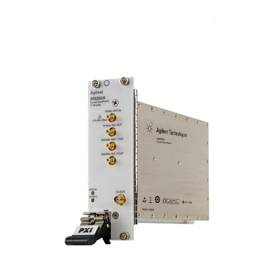
Page 15: Agilent M9302A Pxi Local Oscillator Front Panel Features
0 ± 4 dBm. NOTE: For best measurement performance, connect a high-quality 10 MHz reference to the M9302A REF IN input. If no other reference is available, connect the 10 MHz reference supplied on the back of the PXI chassis. -
Page 16: High-Level Diagnostic Tools, Processes And References
Operational Check (page 18) Specifications The Data Sheet for the M9302A is included on the Agilent M9392A VSA Software and Product Information CD that came with your module.This document contains specification information. To find the latest update, go to http://cp.literature.agilent.com/litweb/pdf/5990-6053EN.pdf. -
Page 17: Front Panel Leds
Description STATUS This LED indicates the overall health of the M9302A and is a summary of the fol- lowing LEDs, covering the power supplies and other hardware operations. The M9302A has extensive built-in-tests (BIT) and specific issues can be identified by observing the status indicator on the front panel. -
Page 18: Block Diagram
Requirements for Operational Check The Agilent M9302A PXI Local Oscillator operational check measures the LO OUT signal and uses that as a ref- erence to compare the signal paths to the 10 MHz REF OUT and the two 100 MHz REF OUT connectors. The fol- lowing process demonstrates that all associated connectors, cables and circuitry are operational. - Page 19 If self test passes, go to next step. b. If self test fails, the module needs repair. 3. Check the voltage and PLL indicators. They are GREEN if the power supplies are good and the M9302A LO and Reference loops are locked.
- Page 20 1. Verify that all relevant hardware is turned on. 2. Verify that the M9302A paths are correctly set from the SFP and that the signal generator is set to the proper power/frequency and that all cables are properly connected. All SMA connectors are torqued to 8 Lb-In (0.904 Nm).
-
Page 21: Performance Verification Tests
Measurement Frequencies The signal frequency at which the 10 MHz lock status is checked is equal to the lock range of the M9302A plus an addition offset based on the frequency accuracy of the signal source internal frequency reference. It is assumed that an E8257D is the signal source and that the calibration interval is 3 years. -
Page 22: Output Power Test
Output Power Test Test Method This test measures the output power of at the LO OUT port and the three reference output ports of the M9302A LO module by direct measurement using a power meter and power sensor. Agilent M9302A PXI Local Oscillator Service Guide... - Page 23 4. Perform a power meter zero and calibration on the power sensor. 5. Open the M9302A soft front panel (SFP) and set the LO Frequency to 3.0 GHz (default value). 6. Connect the power sensor to the LO OUT connector on the M9302A (see Figure 1).
- Page 24 6. Disconnect the power sensor from the 10 MHz REF OUT port and connect it to the 100 MHz REF 1 OUT port. (see Figure 2) 7. Set the power meter measurement frequency to 100 MHz. 8. Record the power reading from the power meter for the 100 MHz REF 1 OUT port. Agilent M9302A PXI Local Oscillator Service Guide...
-
Page 25: Phase Noise Test
Source ≤ -115 dBc/Hz @10 GHz, 10 kHz Offset M9302A Data Sheet Equipment Table 2 Equipment Supported Models Signal Analyzer Agilent N9030A, Opt 513 + N9068A Phase Noise Measurement Cable: APC 3.5 8120-4921 Agilent M9302A PXI Local Oscillator Service Guide... - Page 26 5. On the signal analyzer, perform an Auto Align now. 6. Connect the M9302A 10 MHz REF OUT port to the 10 MHz REF IN port of the signal analyzer. 7. Connect the M9302A LO OUT port to the RF IN port of the signal analyzer.
-
Page 27: Harmonic Distortion Test
Performance Verification Tests Harmonic Distortion Test Test Method This test measure the second harmonic distortion of the LO Output of the M9302A LO module. Limitations and Considerations Methodology This measurement is made using a signal analyzer. However, the signal analyzer frequency response is calibrated using a two-resistor splitter and a power sensor prior to measuring harmonic distortion. - Page 28 3. Turn on the PXI chassis and allow it to warm up for 15 minutes. 4. Perform a power meter zero and calibration on the power sensor. 5. Open the M9302A soft front panel and set the LO Frequency to 3 GHz (default value). 6. Connect the equipment as shown in Figure 1.
- Page 29 6.0 GHz 6.5 GHz 7.0 GHz 7.5 GHz 8.0 GHz 8.5 GHz 9.0 GHz 9.5 GHz 10.0 GHz a. Set the signal source frequency. b. Set the signal source power to 0 dBm. Agilent M9302A PXI Local Oscillator Service Guide...
- Page 30 Disconnect the 10 dB fixed attenuator from the two-resistor splitter. b. Using an RF cable, connect the 10 dB fixed attenuator to the M9302A LO OUT port,. 3. Measure the second harmonic distortion. For each LO frequency in Table 5: a.
-
Page 31: Service
Service Service This section provides reference information and procedures to help you service your Agilent M9302A . In this section: Replaceable Parts (page 31) Module Core Replacement (page 32) Test Record Card (page 36) Replaceable Parts Cable Reference Agilent Part... -
Page 32: Module Core Replacement
3. Write down the serial number shown on the side shield of the defective module. You will assign this serial number to the replacement module using the Agilent M9392A Serial Number Update Utility. 4. Remove the replacement module from the box and shipping material. Agilent M9302A PXI Local Oscillator Service Guide... - Page 33 NOTE: Keep the screws; extra screws are not included with the replacement module. b. Slide the shield toward the module's front panel. This aligns the engagement tabs so you can remove the shield. Agilent M9302A PXI Local Oscillator Service Guide...
- Page 34 7. Attach the original side shield from the defective module to the replacement module. a. Position the side shield so that the screw tabs align with the screw holes on the module, and then slide the side shield against the front panel. Agilent M9302A PXI Local Oscillator Service Guide...
- Page 35 Examples), and install it on your computer or embedded controller. b. Launch the Agilent M9392A Serial Update Utility (launch from the Start menu program group “Agi- lent Utilities”) and follow the embedded instructions for programming the serial number. Agilent M9302A PXI Local Oscillator Service Guide...
-
Page 36: Test Record Card
Click the link below to open the Test Record Card (a PDF form). Save the file to your hard drive and fill in as needed to record your test results. Open Test Record Card TIP: Use Ctrl/click to open the Test Record Card as a separate document. Agilent M9302A PXI Local Oscillator Service Guide... - Page 38 As with a tangram, the possibilities may seem infinite as you begin to create For more information on Agilent Technologies' products, applications or services, please contact your local Agilent office. a new test system. With a set of clearly defined elements—...