Table of Contents
Advertisement
Quick Links
Type 8647
AirLINE SP
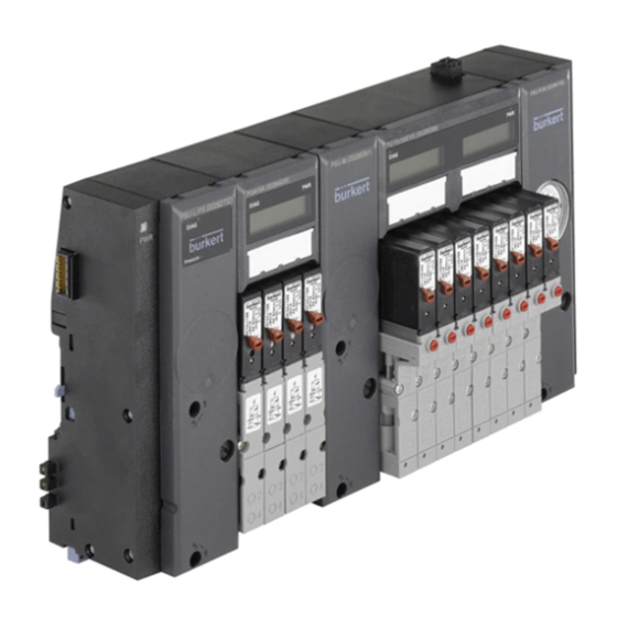
Valve block AirLINE SP
with interface to the distributed I/O system
SIMATIC ET 200SP and
SIMATIC ET 200SP HA (Siemens)
Ventilblock AirLINE SP
mit Schnittstelle zum dezentralen Peripheriesystem
SIMATIC ET 200SP und SIMATIC ET 200SP HA (Siemens)
Bloc de vannes AirLINE SP
avec interface vers le système de périphérie décentralisée
SIMATIC ET 200SP et SIMATIC ET 200SP HA (Siemens)
Quickstart
English
Deutsch
Français
Advertisement
Table of Contents

Subscribe to Our Youtube Channel
Related Manuals for Burkert 8647 AirLINE SP


Summary of Contents for Burkert 8647 AirLINE SP
- Page 1 Type 8647 AirLINE SP Valve block AirLINE SP with interface to the distributed I/O system SIMATIC ET 200SP and SIMATIC ET 200SP HA (Siemens) Ventilblock AirLINE SP mit Schnittstelle zum dezentralen Peripheriesystem SIMATIC ET 200SP und SIMATIC ET 200SP HA (Siemens) Bloc de vannes AirLINE SP avec interface vers le système de périphérie décentralisée SIMATIC ET 200SP et SIMATIC ET 200SP HA (Siemens)
- Page 2 We reserve the right to make technical changes without notice. Technische Änderungen vorbehalten. Sous réserve de modifications techniques. © Bürkert Werke GmbH & Co. KG, 2017 - 2019 Operating Instructions 1906/02_EU-ML_00810496 / Original DE...
-
Page 3: Table Of Contents
Type 8647 Type 8647 Contents connecTinG ..............20 The QuicksTarT ..............4 8.1 Pneumatic Installation............21 1.1 Definitions of terms ............. 4 8.2 Electrical installation ............23 1.2 Symbols ................5 confiGuraTion ............... 25 auThorized use ............... 5 10 sTarT-ups ................. 26 Basic safeTy insTrucTions .......... -
Page 4: The Quickstart
Device, Valve block AirLINE SP Type 8647 The operating instructions can be found online at valve block www.burkert.com Valve terminal Valve block AirLINE SP Type 8647 in Keep the quickstart in a location which is easily accessible to combination with modules from the... -
Page 5: Symbols
Type 8647 Authorized use Symbols auThorized use Danger The valve block airline sp Type 8647 is intended for activating pneumatic consumers in automation systems. warns of an immediate danger. The valve block should only be used to activate suitable ▶ Failure to observe the warning will result in a fatal or serious pneumatic consumers. -
Page 6: Basic Safety Instructions
Type 8647 Basic safety instructions Basic safeTy insTrucTions ▶ Use the device only in conjunction with third-party devices and components recommended and authorized by Bürkert. These safety instructions do not consider any contingencies or ▶ Do not operate the device unless it is in perfect working incidents which occur during assembly, operation and mainte- nance. - Page 7 Type 8647 Basic safety instructions risk of injury due to unintentional activation and uncontrolled In the event of a near-accident, inform the responsible start-up of the device and system. operator. ▶ Secure the device and system to prevent unintentional activation. noTe ▶...
-
Page 8: General Information
D-74653 Ingelfingen simaTic eT 200sp Tel. + 49 (0) 7940 - 10-91 111 System manual: Fax + 49 (0) 7940 - 10-91 448 https://support.industry.siemens.com/cs/ww/en/ Email: info@burkert.com view/58649293 Manual collection: International https://support.industry.siemens.com/cs/ww/en/ view/84133942 Contact addresses can be found on the final pages of the printed quickstart guide. And also online at: www.burkert.com... -
Page 9: Conformity
Type 8647 System Overview Conformity sysTem overview The device conforms to the EC directives as per the EC Decla- Combining modules from the distributed Siemens I/O systems ration of Conformity (if applicable). SIMATIC ET 200SP / SP HA with the valve block AirLINE SP Type 8647 provides an integrated system of electronic and pneumatic Under certain circumstances, SIMATIC ET 200SP / SP HA components. -
Page 10: Connection Units
Type 8647 System Overview Connection units Valve block AirLINE SP Type 8647 is a modular, electro-pneu- matic system consisting of connection and valve units. It is Connection unit, LED display intended for complete integration into the distributed Siemens (only connection right I/O systems “SIMATIC ET 200SP” and “SIMATIC ET 200SP HA”. -
Page 11: Valve Units
Type 8647 System Overview Valve units result, the safety shutdown of all valves of this base module is possible (e.g. for “Central system off”). 8-slot valve unit 4-slot valve unit overview of electronic base modules Electronic base designation number overall valve evs** module number of valve width type* slots... -
Page 12: Solenoid Valves That Can Be Integrated For Pneumatics
Type 8647 System Overview Solenoid valves that can be integrated 5.4.1 Pilot-operated double check valve: Type 0498 for pneumatics The pilot-operated double check valve, Type 0498, can be used Type function to run a 5/3-way function. 6524 3/2-way valve or 2x3/2-way valve It is available as an accessory and is not a component of the 6525 5/2-way valve... -
Page 13: Application Planning
System manual: Further information and data sheets on the pilot- https://support.industry.siemens.com/cs/ww/en/ operated double check valve, Type 0498, can be found view/109761547 on the Internet under www.burkert.com. Manuals: https://support.industry.siemens.com/cs/ww/en/ ps/24728/man For use in areas at risk of explosion, note the information provided in chapter “2 Authorized use”, page 5. -
Page 14: Airline Sp Type 8647 In Combination With Simatic Et 200Sp Ha
Type 8647 Application Planning AirLINE SP Type 8647 in combination on the applied modules of SIMATIC ET 200SP / SP HA (also see with SIMATIC ET 200SP HA the system manual SIMATIC ET 200SP / SP HA ). The valve block is integrated into the I/O system via the SIMATIC consider the following when planning the power ET 200SP HA profile rail. supply: A SIMATIC ET 200SP BaseUnit is required directly to the left of Based on the properties of the applied valves, the the valve block (for the load voltage supply). - Page 15 Type 8647 Application Planning 6.3.3 Valve block in combination with 6.3.2 Valve block in combination with SIMATIC ET 200SP HA SIMATIC ET 200SP Number of 56 I/O modules / connection units / elec- Number of 64 I/O modules / connection units / elec- modules tronic basic modules in complete valve island modules tronic basic modules in complete valve island...
-
Page 16: Installation
Type 8647 Installation insTallaTion The valves are an exception to this rule and may be replaced with identical valves by the user. WarnIng risk of injury from improper assembly. Removing the transportation safety ▶ Only trained technicians may perform assembly and disas- device from the valve block sembly work. -
Page 17: Installing The Valve Block On The Standard Rail In The Control Cabinet
Type 8647 Installation Installing the valve block on the Upper edge of control cabinet standard rail in the control cabinet noTe ≥ 50 (80) mm ≥ 1 25 (155) mm ▶ Observe the specifications in the configuration file for the installation sequence. ▶ Ground the standard rail with low impedance to guarantee Valve block the best possible EMC protection. -
Page 18: Installing The Valve Block On The Base Of The Control Cabinet (With Airline Quick)
Type 8647 Installation → Tighten the fastening screws clockwise (tightening torque noTe approx. 1.8 Nm). ▶ Observe the specifications in the configuration file for the → Attach the BaseUnits of SIMATIC ET 200SP / SP HA to the installation sequence. standard rail on the left of the valve block according to the ▶ Ground the standard rail with low impedance to guarantee instructions provided by the manufacturer. -
Page 19: Disassembling From The Standard Rail In The Control Cabinet
Assignment of the pneumatic connections and the dimensions of the flange images can be found online at: pneumatically. www.burkert.com If the device has been connected electrically and pneumati- cally, carry out the following before disassembling: ▶ Secure the actuators against moving. -
Page 20: Connecting
Type 8647 Connecting connecTinG Danger risk of injury from high pressure. Suddenly escaping pressure medium can quickly accelerate device components (hoses, small parts, ...) resulting in injuries and/or damage. ▶ Before working on the device or system, switch off the pres- sure. Vent or drain lines. Actuators may change their position when the pressure changes. -
Page 21: Pneumatic Installation
Type 8647 Connecting Pneumatic Installation CauTIon risk of injury due to discharge of medium and Danger malfunctioning. risk of injury from high pressure. Medium may escape if the seals are not seated correctly. The ▶ Before loosening lines and valves, turn off the pressure and function of the device may be restricted by pressure losses. vent the lines. - Page 22 Type 8647 Connecting 8.1.1 Pneumatic installation of the connection 8.1.2 Pneumatic installation of the valve units units noTe For 3/2-way valves, the upper connections remain free. 1 (upper connections) Fig. 11: Pneumatic installation of connection units 2 (lower connections) Fig. 12: Pneumatic installation of valve units pos.
-
Page 23: Electrical Installation
Type 8647 Connecting If further BaseUnits of SIMATIC ET 200SP are to be installed Configuration of the connections is displayed on the to the right of the valve block (not permissible in combination housing for Type 6524 and Type 6525 valves. with SIMATIC ET 200SP HA!), the first BaseUnit must be a light- Information about assignment of the valves can be colored BaseUnit (type code BU...D or BU...D/T) to supply the written to the reference identification labels of the elec- necessary load voltage. - Page 24 Type 8647 Connecting the power supply of the valves to this module, e.g. to implement WarnIng functions such as “Central system off” or deactivate actuators group by group. risk of injury and material damage due to electrical faults. An interruption on the EVS connection will immediately cause a If the EVS connections are not connected properly, there is a single-pole interruption of the common supply to all valves of the risk of injury due to the uncontrolled reaction of the system.
-
Page 25: Configuration
EVS, the messages remain. If a short circuit The procedure for configuration is described in the operating or wire break occurred after shutdown via EVS, no diagnostics instructions for type 8647. will be generated. The operating instructions can be found online at www.burkert.com english... -
Page 26: Start-Ups
Type 8647 Start-Ups START-UPS 10.1 Electrical start-up CauTIon WarnIng Undefined reaction of the valves. risk of injury from improper operation. The reaction of the valves is undefined if the supply voltage Improper operation may result in injuries as well as damage to is too low. This may result in unintentional processes in the the device and its environment. -
Page 27: Pneumatic Start-Up
Type 8647 Start-Ups Electrical start-up of the valve island corresponds to start-up of procedures before pneumatic start-up the Siemens distributed I/O system SIMATIC ET 200SP / SP HA. → Check connections, voltage, and operating pressure. The steps necessary for electrical start-up can be found in the → Check correct assignment of the connections 1 and 3 / 5. Siemens system manual “Distributed I/O system ET 200SP” or They may by no means be interchanged. -
Page 28: Manual Activation Of The Valves
Type 8647 Start-Ups 11.1 Manual activation of the valves 11.2 LED display connection units The left-hand connection units feature the LED display WarnIng “PWR OK” for visual display of the operating state. If the connection units are equipped with a pressure sensor risk of injury due to actuators. (“PSU-..-PS”), they feature further LED displays: Unintentional system movements or states may result from - “DIAG” LED (red / green) for module status... -
Page 29: Led Display Of Electronic Base Modules
Type 8647 Start-Ups 11.3 LED display of electronic base 11.4 LC display of electronic base modules modules The electronic base modules (part of the valve unit) feature an LC display for displaying the device status. The switching position The electronic base modules (part of the valve unit) feature two and possible fault states of the outputs are graphically presented LED displays: on the display. Depending on the module configuration, further... - Page 30 Type 8647 Start-Ups 11.4.1 Pressure value display 11.4.3 Display contents The pressure value display is generally intended for use during Display view with four positions start-up. (from left to right channel 0–3 or Depending on the parameterization, the value ist displayed channel 4–7) Display view with eight positions –...
-
Page 31: Diagnostics Reaction
Type 8647 Start-Ups Channel 0 activated Wire break at channel 2 Message 1 / Message 2 Message 1 / Message 2 alternating: External Valve Shutdown active alternating: Message 1: Process data sent by the control. Message 1 Message 1 These are shown on the display Wire Break EVS Active despite “EVS active”. -
Page 32: Maintenance
Type 8647 Maintenance mainTenance risk of injury due to pressure change at pneumatic base modules with P shutoff. WarnIng When the valve is removed, only the P channel is shut off. As risk of injury due to improper installation and maintenance. a result, the existing pressure at the outputs A or B is released. ▶... -
Page 33: Troubleshooting
Type 8647 Troubleshooting TrouBleshooTinG → Using a screwdriver, loosen the fastening screws of the valve. → Remove the valve with flange seal from the valve block. 13.1 Valve reaction → Connect a new valve with correctly inserted flange seals to malfunction possible cause corrective action the valve slot. → Tighten the fastening screws in diagonal pairs while observe Valves do not No or insufficient load Check the electrical... - Page 34 Type 8647 Troubleshooting malfunction possible cause corrective action malfunction possible cause corrective action Valves do not Channel not released Change adjustment of Valves switch Inadequate or no Design the pressure switch for use the parameters with a delay pressure supply supply with the largest or blow possible volume (even...
-
Page 35: Module Reaction
Type 8647 Troubleshooting 13.2 Module reaction malfunction possible cause corrective action 13.2.1 LED display PSU-L-...connection units LED PWR No or insufficient Check the electrical off (only PQ load voltage connection malfunction possible cause corrective action modules) Ensure correct load LED PWR No or insufficient load Check the electrical voltage OK off voltage (see chapter... -
Page 36: Lc Display Of Pq Modules
Type 8647 Troubleshooting 13.3 LC display of PQ modules message possible cause corrective action An overview of the possible display contents is provided in feedback Error at lower or Eliminate error at feedback chapter “11.4 LC display of electronic base modules”. err down x upper feedback indicator indicator to message... -
Page 37: Technical Data
Type 8647 Technical data Technical daTa message possible cause corrective action 14.1 operating conditions wire Break Wire break on Check plug-in connection ch. x output channel x WarnIng (valve or plug-in Replace valve connection faulty) malfunction if used outside. Display per- Module has Change module configu- Extreme outdoor temperatures, condensate formation or... -
Page 38: General Technical Data
Type 8647 Technical data 14.2 general technical data simaTic eT 200sp ha System manual: Dimensions max. 858 mm x 142 mm x 78 mm https://support.industry.siemens.com/cs/ww/en/ (depending on the extension, valve view/109761547 variants, module variants) Manuals: Weight max. 10 kg (depending on the extension) https://support.industry.siemens.com/cs/ww/en/ps/24728/man Material of the PA, PC (valves: PA / PPS / Al) -
Page 39: Pneumatic Data
Type 8647 Technical data 14.3 Pneumatic data Plug-in coupling Ø 6 mm or Ø D1/4 Working connections Control medium Dry compressed air oiled or unoiled, M7 threaded bushing neutral gases Pressure sensor (connection units PSU-...-PS): ISO 8573-1: 2010, class 7.4.4* Compressed air quality as per Measuring range... -
Page 40: Electrical Data
Type 8647 Technical data 14.4 Electrical data Power con- Depending on the system extension, sumption (load max. 3 A Connections: side) Communication Due to the arrangement, the Power con- Depending on the system extension, modules automatically contact the sumption of max. -
Page 41: Type Label
Type 8647 Packaging, Transport, Storage 14.5 Type label PACkAgINg, TRANSPoRT, sToraGe Operating voltage, current type CauTIon Internal code risk of injury due to inappropriate behavior during transportation. Var. Code: XXXX, XXYY ▶ Only trained technicians may transport devices. +/-10% A heavy device can fall down and cause injury during transport Process Control Equipment E238179 Pmax 8 bar or assembly work. - Page 43 www.burkert.com...
Need help?
Do you have a question about the 8647 AirLINE SP and is the answer not in the manual?
Questions and answers