Table of Contents
Advertisement
Quick Links
Advertisement
Table of Contents
Troubleshooting

Subscribe to Our Youtube Channel
Related Manuals for Burkert AirLINE 8652 Series


Summary of Contents for Burkert AirLINE 8652 Series
- Page 1 Type 8652 AirLINE Modular valve island for pneumatics Operating Instructions...
- Page 2 We reserve the right to make technical changes without notice. © Bürkert Werke GmbH & Co. KG, 2017 - 2022 Operating Instructions 2211/17_EUen_00810541 / Original DE...
-
Page 3: Table Of Contents
Type 8652 Type 8652 Valve island AirLINE Type 8652 ontents OPERATING INSTRUCTIONS ........................6 Symbols ............................6 1.2 Definition of terms ........................7 INTENDED USE ............................8 BASIC SAFETY INSTRUCTIONS ......................9 GENERAL NOTES..........................11 4.1 Contact address .........................11 4.2 Warranty .............................11 4.3 Information on the Internet ......................11 PRODUCT DESCRIPTION ........................12 5.1 Product structure ........................13 5.2 External safety-related shutdown of valves ................16... - Page 4 Type 8652 INTEGRATION INTO THE CONTROL ENVIRONMENT ................46 10.1 Start-up files and description of the process data and parameters........46 10.2 PLC compatibility ........................46 10.3 Commissioning a PROFINET device with Siemens TIA Portal ..........48 10.4 Commissioning a PROFIBUS DPV1 device with Siemens TIA Portal ........51 10.5 Commissioning an EtherNet/IP device with Rockwell Logix Designer ........54 10.6 Bit-wise composition of the inputs and outputs ..............57 10.7 Advanced gateway functionalities ....................57 CONFIGURATION WITH WEB SERVER ....................58 11.1 Establishing a connection to the web server................58 11.2 Logging onto the web server .....................59 11.3 Passwords ..........................59 11.4 Finding the device ........................59 11.5 Disabling web server access with Bürkert Communicator ............60 11.6 Information in the web server ....................60 11.7 Setting options in the web server .....................60...
- Page 5 Type 8652 16.6 Switch time monitoring of actuators ..................75 16.7 Disabling access to web server ....................75 16.8 Using Extension Modules (EM) ....................76 BÜRKERT COMMUNICATOR MENU STRUCTURE ................78 START-UP .............................83 18.1 Safety instructions ........................83 18.2 Commissioning via manual override ..................83 18.3 Identification of the valve positions ..................84 DISPLAYS .............................85 19.1 Description of displays ......................85 COMBINE VALVE ISLAND WITH EXTERNAL DI MODULES ...............88 20.1 Assign position feedback sensor source in the automation software ........88 20.2 Assign position feedback sensor source in Bürkert Communicator ........88 20.3 Network configuration in the Bürkert Communicator ..............89 20.4 Show errors from büS partners on the display .................93 20.5 Configure external DI modules using a wizard .................94 SWITCH TIME MONITORING FUNCTION ...................95...
-
Page 6: Operating Instructions
Type 8652 Operating Instructions OPERATING INSTRUCTIONS The operating instructions describe the entire life cycle of the device. → Keep these instructions ready to hand at the operation site. Important safety information! Carefully read these instructions. ► Observe in particular the safety instructions, intended use and operating conditions. ►... -
Page 7: Definition Of Terms
Information on cabling büS networks can be found in the " Cabling Guide for büS / EDIP ". You can find the “ Cabling Guide for büS / EDIP ” in the “Operating Instructions” area for type 8652 on the Bürkert homepage country.burkert.com. English... -
Page 8: Intended Use
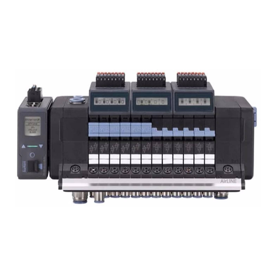
Type 8652 Intended use INTENDED USE The AirLINE type 8652 valve island is designed to control and record the switching states of pneumati- cally operated process valves. Use the device only as intended. Non-intended use of the device may be dangerous to people, nearby ► equipment and the environment. In the potentially explosive atmosphere, only use devices that are approved for this purpose. These ►... -
Page 9: Basic Safety Instructions
Type 8652 Basic safety instructions BASIC SAFETY INSTRUCTIONS These safety instructions do not take into account any unforeseen circumstances or events that occur during installation, operation and maintenance. The operator is responsible for observing the location-specific safety regulations, also with reference to personnel. Risk of injury from high pressure and uncontrolled movement of the actuators. - Page 10 Type 8652 Basic safety instructions CAUTION Electrostatically sensitive components and assemblies. The device contains electronic components that are susceptible to the effects of electrostatic discharging (ESD). Components that come into contact with electrostatically charged persons or objects are at risk. In the worst case scenario, these components will be destroyed immediately or fail after start-up.
-
Page 11: General Notes
D-74653 Ingelfingen Tel. +49 (0) 7940 - 10 91 111 Fax +49 (0) 7940 - 10 91 448 Email: info@burkert.com International The contact addresses can be found on the back pages of the printed Quickstart. They are also available online at: country.burkert.com... -
Page 12: Product Description
Type 8652 Product description PRODUCT DESCRIPTION Thanks to its compact and modular structure with regard to pneumatic and electrical interfaces, the AirLINE type 8652 valve island is suitable for solving diverse and complex control tasks. The structure of the valve island is optimised for use in control cabinets. The AirLINE Quick adapter plate is already part of the valve island in the basic configuration. -
Page 13: Product Structure
Type 8652 Product description Product structure 24V interface board 24V interface board with module-based shutdown without module-based shutdown Electronic module Electronic module with digital inputs Supply manifold complete (hot swap) Fieldbus gateway ME43 Terminating resistor Connection module with pressurised air intake and integrated pressure sensor Connection module... - Page 14 Type 8652 Product description 5.1.3 Interface board Optional: connections for module-based safety shutdown 24 V supply voltage for pneumatic valves Figure 3: Connections for EVS on the interface board The interface board has a 2-pole spring-loaded terminal to which the supply voltage for the pneumatic slide valves is connected.
- Page 15 8652 (see country.burkert.com Pneumatic slide valves type 6534 are equipped with manual override. The manual override works without voltage being applied to the valve island and allows manual valve switching (see chapter “18.2”).
-
Page 16: External Safety-Related Shutdown Of Valves
Type 8652 Product description External safety-related shutdown of valves There are several ways to de-energise valves irrespective of the control signals from the bus master. • Single valves only Pneumatic slide valves Type 6534 “SIA variant” are equipped with additional connection terminals. The circuit of a valve can therefore be interrupted by an external switch. -
Page 17: Technical Data
Type 8652 Technical data TECHNICAL DATA Standards and directives The device complies with the relevant EU harmonisation legislation. In addition, the device also complies with the requirements of the laws of the United Kingdom. The harmonised standards that have been applied for the conformity assessment procedure are listed in the current version of the EU Declaration of Conformity/UK Declaration of Conformity. -
Page 18: General Electrical Data
Type 8652 Technical data General electrical data CAUTION Use safety extra-low voltage according to protection class III EN 61140, VDE 0140. ► Nominal operating Continuous operation (100% duty cycle) mode Operating voltage 24 V ± 10%, residual ripple with fieldbus interface max. 1 Vss Current consumption The current consumption depends on the configuration of the valve island. -
Page 19: Electrical Data Of Electronic Module With Digital Inputs
Type 8652 Technical data Electrical data of electronic module with digital inputs Module properties Diagnostics Wire break detection for 2-wire sensors Short circuit detection for 3-wire sensors Safety Protection against overvoltage Electrical data Electrical connection (position feedback 2-wire sensors sensor) 3-wire sensors Mechanical limit switches Input type Type 1 and type 3 according to IEC 61132-2... -
Page 20: Pneumatic Slide Valve Type 6534
Type 8652 Technical data Pneumatic slide valve type 6534 Circuit function (CF) 2 x CFC CF H NC (normally closed) 5/2-way monostable 5/3-way blocked 2 x 3/2-way 2 x CFD 5/3-way pressurised NO (normally open) 5/2-way bistable 2 x 3/2-way 5/3-way vented Flow rate Q up to 310 l / min... -
Page 21: Circuit Function (Cf)
Type 8652 Technical data Circuit function (CF) Circuit function (CF) Symbol according to ISO 1219-1 Description 2 x CFC Outlet 2 and outlet 4 vented when idle. 2 x CFD Outlet 2 and outlet 4 aerated when idle. CF H Pressure port 1 connected to outlet 2 when idle, outlet 4 vented. -
Page 22: Standard Type Label (Example)
Type 8652 Technical data Standard type label (example) Type 8652 AirLINE 3-10 bar permissible pilot pressure range -10...+55°C permissible ambient temperature range Operating voltage, current consumption S/N 0 W14AL 12345678 Figure 5: Type label standard valve island type 8652 Type label UL (example) Type 8652 AirLINE 3-10 bar -10...+55°C... -
Page 23: Industrial Ethernet Specifications
Type 8652 Technical data 6.10 Industrial Ethernet specifications 6.10.1 PROFINET IO Topology recognition LLDP, SNMP V1, MIB2, Physical Device Minimum cycle time 10 ms not supported MRP media redundancy MRP client is supported Other supported functions DCP, VLAN Priority Tagging, Shared Device Transmission speed 100 Mbit/s Data transport layer... - Page 24 Type 8652 Technical data 6.10.3 Modbus TCP Modbus function codes 1, 2, 3, 4, 6, 15, 16, 23 Operation mode Message mode: Server Transmission speed 10 and 100 MBit/s Data transport layer Ethernet II, IEEE 802.3 6.10.4 EtherCAT Ethernet interface X1, X2 X1: EtherCAT IN X2: EtherCAT OUT Maximum quantity of cyclical input...
-
Page 25: Specifications Profibus Dpv1
Type 8652 Technical data 6.11 Specifications PROFIBUS DPV1 Acyclic communication DPV1 Class 1 Read/Write DPV1 Class 1 alarm DPV1 Class 2 Read / Write / Data Transport Transmission speed fixed values from 9.6 kbit / s to 12 Mbit / s Autodetect mode is supported Maximum size of the transferred Input data: 244 Byte... -
Page 26: Installation Of The Valve Island In The Control Cabinet
Type 8652 Installation of the valve island in the control cabinet INSTALLATION OF THE VALVE ISLAND IN THE CONTROL CABINET WARNING Risk of injury due to improper installation. Only trained technicians may perform installation work. ► Perform installation work using suitable tools only. ► CAUTION Risk of injury due to heavy device. During transportation or installation work, a heavy device may fall down and cause injuries. -
Page 27: Installation On The Control Cabinet Floor Or The Control Cabinet Wall With Airline Quick
Type 8652 Installation of the valve island in the control cabinet Installation on the control cabinet floor or the control cabinet wall with AirLINE Quick WARNING Danger due to electromagnetic disruptions. If the functional earth (FE) is not connected, then the requirements of the EMC protection are not met and malfunctions may occur on the unit. - Page 28 Type 8652 Installation of the valve island in the control cabinet Mounting plate A-A (1 : 2) min. 60,5 max. 19,5 min. 73 Distance between the rear wall of the control cabinet and the mounting plate Figure 9: To be able to use the Hot-Swap function, there must be a minimum distance from the front edge of the control cabinet when installing the valve island in the control cabinet.
- Page 29 Type 8652 Installation of the valve island in the control cabinet Number of valves M [mm] N1 [mm] N2 [mm] Number of holes 85.8 ±0.3 66 ±0.3 – 129.8 ±0.4 37 ±0.3 111 ±0.4 173.8 ±0.4 77 ±0.3 154 ±0.4 244 ±0.4 112 ±0.3 224 ±0.4 288 ±0.4 134 ±0.3 268 ±0.4 332.1 ±0.4...
-
Page 30: Standard Rail Installation
Type 8652 Installation of the valve island in the control cabinet Standard rail installation WARNING Danger due to electromagnetic disruptions. If the functional earth (FE) is not connected, then the requirements of the EMC protection are not met and malfunctions may occur on the unit. Connect the standard rail to the functional earth (FE) using a short cable with a large cross-section or ►... - Page 31 Type 8652 Installation of the valve island in the control cabinet Figure 12: Fastening screws for valve island on standard rail English...
-
Page 32: Electrical Connection
Information on cabling büS networks can be found in the " Cabling Guide for büS / EDIP ". You will find the “Cabling Guide for büS / EDIP ” in the “Operating Instructions” area for type 8652 on the Bürkert homepage country.burkert.com Fieldbus gateway ME43 8.2.1 Gateway with CANopen / büS interface... - Page 33 Type 8652 Electrical connection 8.2.2 Gateway with Industrial Ethernet interface The following protocols are supported: • EtherCAT • EtherNet/IP • Modbus TCP • PROFINET • CC-Link IE field basic → Connect 5-pin spring-loaded terminal according to the assignment. Possible cable cross-section: ≤ 1.5 mm (see also Chapter“28 Accessories”...
- Page 34 Type 8652 Electrical connection 8.2.3 Gateway with PROFIBUS DPV1 interface → Connect 5-pin spring-loaded terminal according to the assignment. Possible cable cross-section: ≤ 1.5 mm (see also Chapter“28 Accessories” ) → Connection of a 9-pin D-Sub plug to the PROFIBUS DPV1 interface according to the assignment. Assignment 5-pin spring-loaded terminal Plug view Terminal colour...
- Page 35 Type 8652 Electrical connection 8.2.4 Gateway with CC-Link interface → Connect 5-pin spring-loaded terminal according to the assignment. Possible cable cross-section: ≤ 1.5 mm (see also Chapter“28 Accessories” ) → Connection of a D-sub 9-pin plug to the CC-L ink - interface according to the assignment. Assignment 5-pin spring-loaded terminal Plug view Terminal colour...
-
Page 36: Supply Voltage For Pneumatic Valves
Type 8652 Electrical connection 24 V supply voltage for pneumatic valves The interface board has a 2-pole spring-loaded terminal to which the supply voltage for the pneumatic valves is connected. This allows the voltage for all pneumatic valves of the valve island to be shut down irrespective of the communication to the superordinate controller (PLC). -
Page 37: Electronic Module With Digital Inputs (Optional)
Type 8652 Electrical connection Electronic module with digital inputs (optional) → Switch off the supply voltage. → Connect the position feedback sensors to the electronics module according to the assignment. Possible cable cross-section: ≤ 1.5 mm Maximum cable length: <30 m The electrical supply to the position feedback sensors (24 V) is provided by the electronic module. -
Page 38: Electrical Connection Assignment
Type 8652 Electrical connection Electrical connection assignment 8.5.1 Upper end position Valve unit with 4 pieces 2x3 / 2-way valves Upper end position (= 8 position feedback sensor inputs) 8 bit reported binary value: 0b10010111 Figure 18: Example of upper end positions for a valve unit with 4 2x3 / 2-way valves 8.5.2 Lower end position Valve unit with 4 pieces 2x3 / 2-way valves... -
Page 39: Valves Type 6534 For Safety-Related Shutdown, Variant Sia (Optional)
Type 8652 Electrical connection Valves type 6534 for safety-related shutdown, variant SIA (optional) DANGER Risk of injury due to unintentional movement of the actuators. If the shut-off function is required to control safety-critical processes, hazardous movements of the actu- ators may be triggered when the switch-off function is faulty. ▶... - Page 40 Type 8652 Electrical connection Connection terminals: Pluggable screw-type terminal, 2-pole, coded wire cross-section (rigid or flexible) 0.14 mm²...1.5 mm² (AWG 28...16) 21 → connection terminal 2, pole 1 Labelling connection terminals: 22 → connection terminal 2, pole 2 41 → connection terminal 4, pole 1 42 →...
-
Page 41: Modular Safety-Related Shutdown (Optional)
Type 8652 Electrical connection Modular safety-related shutdown (optional) DANGER Risk of injury due to unintentional movement of the actuators. If the shutdown function “Module-based safety shutdown” is required to control safety-critical proce- dures, hazardous movements of the actuators may be triggered if the shutdown function is faulty. ▶ Make sure the shut-off function is working properly before start-up. In spite of the activated shutdown function, actuators can be moved by manual override of the valves. - Page 42 Type 8652 Electrical connection Backplane bus AUX 24 V Voltage conversion, control logic and LCD Valve driver, diagnostics Valves “Module-based safety shutdown” connection for external potential-free contact Figure 24: Schematic representation of a valve unit with shutdown function “Module-based safety shutdown” To use the shut-off function, connect the connection to a potential-free contact (mechanical switch or relay).
-
Page 43: Pneumatic Connection
Type 8652 Pneumatic connection PNEUMATIC CONNECTION DANGER Risk of injury from high pressure. Secure the actuators against shifting before working on the device or plant. ► Switch off the pressure before working on the device or plant. Vent or empty the lines. ► Risk of injury if the pneumatic connection is incorrect. Only trained specialists are allowed to make the pneumatic connection. ►... - Page 44 Type 8652 Pneumatic connection P / 1 X / 12/14 supply connection pressure port for auxiliary pilot air Filter (for filtering the auxiliary pilot air) Figure 27: Pneumatic connections connection module 9.1.1 External and internal auxiliary pilot air The seals of the connection module are already installed in the delivery state. Should it be necessary to change the supply of the auxiliary pilot air, this can be done by turning the seal.
-
Page 45: Pneumatic Connection Assignment
Type 8652 Pneumatic connection Pneumatic connection assignment Valve unit with 4 double valves BM1_Valves Bit 0 Bit 1 Bit 2 Bit 3 Bit 4 Bit 5 Bit 6 Bit 7 Valve 1 Valve 2 Valve 3 Valve 4 Valve 5 Valve 6 Valve 7 Valve 8 Pneumatic connection Table 7: Example for the assignment of the bits for double valves If there are single valves in a valve unit, the next bit is skipped after a single valve (see following example). -
Page 46: Integration Into The Control Environment
The start-up files required by the project planning software are available on the Internet. Download the start-up files from: → Type 8652 → Software → Device Description Files.zip country.burkert.com You will also find the descriptions of the start-up files in the zip file. → Use the latest start-up file from the "01_Standard" folder (exception: see Chapter“10.2” ). - Page 47 Type 8652 Integration into the control environment 10.2.2 Error alerts concerning PLC compatibility Error code Description Troubleshooting • If extension modules were used, perform the 51/103 No or incorrect mapping file Extension present. module settings wizard again. General settings > Parameter > Extension module settings •...
-
Page 48: Commissioning A Profinet Device With Siemens Tia Portal
Type 8652 Integration into the control environment 10.3 Commissioning a PROFINET device with Siemens TIA Portal → Import the start-up file into the hardware catalogue of the tool. The start-up files of version V2.0 were used in the illustrations shown. →... - Page 49 Type 8652 Integration into the control environment On the right, in the "Catalogue" menu, you will find the modules: → Pressure measuring module Assign the modules to the respective slot by double-clicking or by Valve unit 1 drag and drop. Map the real structure of the valve island from left Valve unit 2 to right.
- Page 50 Type 8652 Integration into the control environment → Then configure the position feedback sensor source for each valve unit. To do this, drag the position feedback sensor source used from the submodules to the corresponding position in the device overview. In the device overview, Subslot 1 corresponds to the valve, Subslot 2 to the position feedback sensor source of the upper end position, Subslot 3 to the feedback source of the lower end position.
-
Page 51: Commissioning A Profibus Dpv1 Device With Siemens Tia Portal
Type 8652 Integration into the control environment 10.4 Commissioning a PROFIBUS DPV1 device with Siemens TIA Portal → Import the start-up file into the hardware catalogue of the tool. The start-up files of version V2.0 were used in the illustrations shown. →... - Page 52 Type 8652 Integration into the control environment On the right, in the "Catalogue" menu, you will find the modules: → Assign the modules to the respective slot by double-clicking or by drag and drop. Map the real structure of the valve island from left to right. Pressure measuring modules (if present) and valve units must be assigned.
- Page 53 Type 8652 Integration into the control environment Module in the catalogue of the TIA Set position feedback sensor source Portal ValvesUnit No position feedback sensor sources are set ValveUnit FB up-term. Upper end position: digital inputs valve island Lower end position: not used ValveUnit FB down-term. Lower end position: digital inputs valve island Upper end position: not used ValveUnit FB up/down-term.
-
Page 54: Commissioning An Ethernet/Ip Device With Rockwell Logix Designer
Type 8652 Integration into the control environment 10.5 Commissioning an EtherNet/IP device with Rockwell Logix Designer → Install EDS file. To do this, click on the EDS Hardware Installation Tool command in the Tools menu. → In the window that opens, click on Register an EDS file. - Page 55 Type 8652 Integration into the control environment → Select the device in the Catalogue tab. To simplify the search for the device: - select the filter "Buerkert Werke GmbH & Co. KG" or - enter the term "Airline" in the search field at the top left. →...
- Page 56 Type 8652 Integration into the control environment → In the New Module window, choose the command Change. The Module Definition window opens. → Pressure measuring module Set the Connections in the Module Definition window: Valve unit 1 - First the number of valve units used, Valve unit 2 - then the number of pressure measurement modules * (if available).
-
Page 57: Bit-Wise Composition Of The Inputs And Outputs
“8.5 Electrical connection assignment” on page 38 “9.2 Pneumatic connection assignment” on page 45 10.7 Advanced gateway functionalities Information on: Control mode (communication settings) and Object Route Function (access to other büS objects) can be found at: country.burkert.com → Type 8652 → Operating instructions → "Definition fieldbus" English... -
Page 58: Configuration With Web Server
Type 8652 Configuration with web server CONFIGURATION WITH WEB SERVER The valve island AirLINE Type 8652 has an integrated web server via which the device can be configured. The web server can be used for the following protocols: • PROFINET • EtherNet/IP •... -
Page 59: Logging Onto The Web Server
Type 8652 Configuration with web server 11.2 Logging onto the web server → On the home page, click on on the top left. Login → Enter your user name and password: User name: admin Password: admin → Click on Login. 11.3 Passwords CAUTION... -
Page 60: Disabling Web Server Access With Bürkert Communicator
Type 8652 Configuration with web server 11.5 Disabling web server access with Bürkert Communicator The web server is enabled upon delivery. Web server access can be disabled via the Bürkert Communicator software (see chapter “16.7” on page 75). 11.6 Information in the web server 11.6.1 Device information •... -
Page 61: Industrial Communication Of Web Server
Type 8652 Configuration with web server • Alarm limits Pressure measurement configuration • Pressure indicators on internal displays • Cyclical output of pressure value Pressure measurement diagnostics Display of the measured values: • Current pressure • Maximum pressure • Minimum pressure Installation of pressure measurement Enabling/disabling pressure sensors 11.8... -
Page 62: Configuration With Fieldbus Gateway
Type 8652 Configuration with fieldbus gateway CONFIGURATION WITH FIELDBUS GATEWAY If the fieldbus gateway is equipped with display and operating elements, settings can be made via the fieldbus gateway. Arrow keys Menu button Figure 32: Overview of operating elements of fieldbus gateway ME43 12.1 Operating the fieldbus gateway Element... -
Page 63: Enter Profibus Address Or Cc-Link Address
Type 8652 Configuration with fieldbus gateway 12.3 Enter PROFIBUS address or CC-Link address → Press the menu button twice. → Select Parameter > Ind. Comm. > Address → menu button to enable processing. → Set, confirm and save the address with the arrow keys. Address menu is only available for PROFIBUS or CC-Link devices. -
Page 64: Display: Contrast, Brightness, Installation Position, Language
Type 8652 Configuration with fieldbus gateway 12.7 Display: contrast, brightness, installation position, language → Press the menu button twice. → Select > Display. Parameter → Select the value to be changed. → menu button to enable processing. → Set the desired value with the arrow keys. →... -
Page 65: Reset The Switching Cycle Counters
Type 8652 Configuration with fieldbus gateway 12.12 Reset the switching cycle counters The switching cycle counters can be reset for the complete valve island (all switching cycle counters of the pilot valves) or for each valve unit (modules). → Press the menu button twice. -
Page 66: Menu Structure Fieldbus Gateway
Type 8652 Menu structure fieldbus gateway MENU STRUCTURE FIELDBUS GATEWAY ro = read only, rw = read / write Parameters Ind. Comm IP setting (with Industrial Ethernet) Address Network Gateway Address (for PROFIBUS DPV1 and CC-Link) Profibus address / CC-Link address Protocol (preset at factory for PROFIBUS and CC-Link) Profibus... - Page 67 Type 8652 Menu structure fieldbus gateway Right Inactive Active Display Contrast Brightness Mounting Reverse Normal Auto Language German English CfgProvid. Diagnosis Type code If the type is "Error", the error code is displayed. Description of the error codes: Page 114 Maintenance Restart Fact.
-
Page 68: Fieldbus Gateway Display Elements
Type 8652 Fieldbus gateway display elements FIELDBUS GATEWAY DISPLAY ELEMENTS LEDs for network connection to Industrial Ethernet Display (available only for the Industrial Ethernet variant) Status LED for indicating the device status Link LED (yellow) RJ45 Link/act LED (green) Figure 33: Overview of the display elements 14.1 LEDs for indicating the network connection to Industrial Ethernet... -
Page 69: Led For Displaying The Device Status
Type 8652 Fieldbus gateway display elements 14.2 LED for displaying the device status The LED for displaying the device status changes colour and status similar to NAMUR NE 107. If various alerts are present, the LED always shines in the colour of the highest prioritised alert (red = outage = highest priority). -
Page 70: 15 Bürkert Communicator Basics
In addition to the software, the USB-büS-interface, available as an accessory, is required (see chapter “28 Accessories”). The operating instructions for the basic functions of the software can be found on the Bürkert → Type 8920 homepage: country.burkert.com Add interface (connect with büS stick) Active user level Detailed views of the... -
Page 71: User Levels
Type 8652 Bürkert Communicator basics 15.1 User levels Bürkert Communicator is operated within user levels. There are 3 user levels, and each one has certain reading rights and writing rights. The active user level is indicated by an icon on the upper left margin of the program window. Icon User level Description... -
Page 72: Connecting The Device To The Bürkert Communicator
Type 8652 Bürkert Communicator basics 15.2 Connecting the device to the Bürkert Communicator → Install Bürkert Communicator on the PC. → Set the terminating resistor (on the büS stick or external terminating resistor). → Use the USB-büS-interface to establish the connection between the device and the PC. →... -
Page 73: Configuration With Bürkert Communicator
The description of the gateway configuration can be found in the fieldbus gateway Type ME43 oper- ating instructions at: www.burkert.com If additional büS devices are connected to the valve island and are to be connected to a controller through them, the valve island can also be configured as a gateway. - Page 74 Type 8652 Configuration with Bürkert Communicator 16.2.4 Enter PROFIBUS address > Parameter> PROFIBUS Settings > PROFIBUS PROFIBUS Address → Enter address. Valid addresses: 0–126 (factory setting value: 3) If an address outside the valid range has been set, the device will issue an error message. 16.2.5 Entering CC-Link address CC-Link > Parameter> CC-Link Settings > CC-Link Address...
-
Page 75: Base Settings Canopen/Büs
Type 8652 Configuration with Bürkert Communicator 16.3 Base settings CANopen/büS If devices feature CANopen/büS communication, the “CANopen” bus operation mode has been preset at the factory. 16.3.1 Switching over bus operation mode Bus operation mode can be switched over to “büS” using Bürkert Communicator. General settings >... -
Page 76: Using Extension Modules (Em)
The description of how to connect other devices with the controller can be found in the fieldbus gateway Type ME43 operating instructions at: www.burkert.com. Extension modules are installed on a valve island with a fieldbus connection. This means that additional valve islands can be controlled via this valve island without a fieldbus connection. - Page 77 Type 8652 Configuration with Bürkert Communicator 16.8.2 Configuring the valve island with extension modules > > General settings Parameter Extension module settings A wizard will guide you through the settings. → Finish A restart is triggered. There are 9 extension modules available. 16.8.3 Configuring the büS network →...
-
Page 78: Bürkert Communicator Menu Structure
Type 8652 Bürkert Communicator menu structure BÜRKERT COMMUNICATOR MENU STRUCTURE Bürkert Communicator is operated within user levels. There are 3 user levels, and each one has certain reading rights and writing rights. See also chapter“User levels” on page 71 . ro = read only, rw = read/write Configuration section “Unit”... - Page 79 Type 8652 Bürkert Communicator menu structure Configuration area "(protocol name)" DNS compatible name Fixed IP address Network interface Standard gateway Temporary IP address MAC address Advanced settings Alarm settings Internal cycle time Control mode settings – – Firmware update protocol – – (EtherNet/IP) IP parameter settings –...
- Page 80 Type 8652 Bürkert Communicator menu structure Configuration area "(protocol name)" Protocol Communication status Control mode settings Established connections to PLC Current internal cycle time Advanced Last status code – – Maintenance Version number Stack name Stack version Stack build Stack revision Stack date ICom version Hardware reset –...
- Page 81 Type 8652 Bürkert Communicator menu structure Configuration section “General settings” Parameter Status LED Operation mode Colour (menu only appears when the “Fixed colour” operation mode is activated) büS Displayed name Location Description Advanced Unique device name Baud rate Fixed CANopen address CANopen address Bus operation mode CANopen status Menu only appears when “CANopen”...
- Page 82 Type 8652 Bürkert Communicator menu structure Configuration section “General settings” supply voltage Voltage drops Min./max. values Min. temperature Max. temperature Min. supply voltage Max. supply voltage Device start counter Removable storage medium status Current system time Battery voltage büS status Receive error Receive error max. Send error Send error max.
-
Page 83: Start-Up
Type 8652 Start-up START-UP 18.1 Safety instructions WARNING Risk of injury due to improper operation. Improper operation may result in injuries as well as damage to the device and the surrounding area. ▶ Before start-up, ensure that the operating personnel are aware of and have completely understood the contents of the operating instructions. -
Page 84: Identification Of The Valve Positions
Type 8652 Start-up The standard manual override is spring return and latching. Spring return: If the sliding mechanism is moved to a first resistor, the manual override returns to the unswitched state after release. Latching: If the resistor is exceeded, the manual override stops in the switched state after release. Slide mechanism must be pushed back manually over the locking point to reset the manual override to the unswitched state 18.2.1 Additional element “Lock Manual Override”... -
Page 85: Displays
Type 8652 Displays DISPLAYS LC display for messages (information, warnings, errors) Figure 40: Display elements on the electronic module The electronic modules are equipped with an LC display for status display. The switch position and pos- sible error states of the outputs are shown graphically on the display. Depending on the configuration of the module, additional information can be displayed, e.g. - Page 86 Type 8652 Displays Short circuit on input 2 of Example of further possible Message 1/message 2 in alternation: the upper position feedback messages: sensor unit Short circuit Message 1 Short circuit on inputs 2–4 of Short circuit the lower position feedback sensor unit Message 2 Wire break on input 2 of the Example of further possible...
- Page 87 Type 8652 Displays Message 1/message 2 in alternation: The switching time of actuator 1, lower end position, has been exceeded (also see “21 Switch time monitoring function” on page 95). Message 1 Act AF Time Act. 1 Message 2 English...
-
Page 88: Combine Valve Island With External Di Modules
External DI modules can, for example, be B. 8DI modules of type ME44 or 16DI modules of type ME64. The start-up files of the valve island already contain the settings of the external DI modules. Download the start-up files from: country.burkert.com → Type 8652 → Software → Device Description Files.zip... -
Page 89: Network Configuration In The Bürkert Communicator
Type 8652 Combine valve island with external DI modules 20.3 Network configuration in the Bürkert Communicator This chapter describes the configuration of valve island / DI module combinations using 3 examples. Where is the network configuration done? User level: Installer → Click in the configuration area on the büS interface →... - Page 90 Type 8652 Combine valve island with external DI modules Network configuration of example 1 in the Communicator: In the example, the following position feedback sensor sources are assigned: Upper end position "External DI module (büS)" lower end position "Integrated DI module" The assignment of the position feedback sensor sources to the upper and lower end positions is arbitrary .
- Page 91 Type 8652 Combine valve island with external DI modules 20.3.2 Example 2: Valve island with 6 valve units without internal DI modules in combination with 8DI modules ME44 A maximum of 2 DI modules are possible per valve unit. In the case of a valve island with 6 valve units without internal DI modules, a maximum of 12 external 8DI modules can be used.
- Page 92 Type 8652 Combine valve island with external DI modules 20.3.3 Example 3: Valve island with 6 valve units without internal DI modules in combination with 16DI modules ME64 A maximum of 2 DI modules with 8 DIs each (= 16 DIs per valve unit) are possible per valve unit. In the case of a valve island with 6 valve units without internal DI modules, 6 16DI modules of type ME64 can be used.
-
Page 93: Show Errors From Büs Partners On The Display
Type 8652 Combine valve island with external DI modules 20.4 Show errors from büS partners on the display If the valve island with a DI module Type ME64 or ME44 is used, wire break or short circuit alerts can be indicated on the valve unit display as though it were an internal module. -
Page 94: Configure External Di Modules Using A Wizard
Type 8652 Combine valve island with external DI modules 20.5 Configure external DI modules using a wizard If the configuration is identical for each valve unit, it is recommended to use a wizard in the Bürkert Communicator. → Assign the position feedback sensor sources in the automation software (see “20.1”). In the Bürkert Communicator, valve island configuration area User level: Installer →... -
Page 95: Switch Time Monitoring Function
Type 8652 Switch time monitoring function SWITCH TIME MONITORING FUNCTION With this function, wear or possible defects in the process valves (actuators) can be detected early by moni- toring the switching time duration, e.g. to optimise maintenance intervals. The valve island can record and permanently monitor the switching times of individual or all actuators in the ongoing process. -
Page 96: Start Switching Time Measurement
Type 8652 Switch time monitoring function Example: The average value determined is 5 s, resulting in a timeout of 15 s. If a switching time >15 s is measured, a maintenance message is issued immediately. A timeout indicates a malfunction of the actuator, e.g. due to a loose hose or a seizure of the actuator. 21.3 Start switching time measurement The switching time measurement can be started using the Bürkert Communicator software, the web server... -
Page 97: Error Messages For The Function Of The Switching Time Monitoring
Switching time measurement start via external controller The objects for starting the switching time measurement via an external controller can be found in the "Device Description files" on the Bürkert homepage under: country.burkert.com → Type 8652 → Software → Device Description files 21.4... -
Page 98: Micro Sd Card
Type 8652 Micro SD card MICRO SD CARD A micro SD card is available as an accessory for the valve island. The micro SD card can be used to store device-specific values and user settings and transfer them to another device. If the micro SD card of the device is re-inserted at a later stage, the data last saved are not restored. - Page 99 Type 8652 Micro SD card Removing the micro SD card: → Pull the cover out of the recess and turn it to the top left. → To unlock, press on the edge of the engaged micro SD card, Remove micro SD card. Insert the micro SD card into the replacement device: O bserve the direction of insertion when inserting the card. →...
-
Page 100: Backup Battery
Type 8652 Backup battery BACKUP BATTERY The device is equipped with a backup battery. The function of the battery relates exclusively to the time recording in the logbook. If the battery is empty, it will not cause a fault in the device. There is only a message in the Bürkert Commu- nicator software. -
Page 101: Replacing Spare Parts
Type 8652 Replacing spare parts REPLACING SPARE PARTS WARNING Risk of injury due to improper installation work. Only trained technicians may perform installation work. ► Perform installation work using suitable tools only. ► The following modules are available as spare part kits for the valve island AirLINE Type 8652 under the type SV04: •... - Page 102 Type 8652 Replacing spare parts Fastening screw of the con- nection module → Observe the safety instructions. → Use a screwdriver (TX 20) to undo the fastening screw of the connection module. → Extract the connection module from the front. → Insert the new connection module and screw it into position (tightening torque 2 Nm).
-
Page 103: Connection Module With Pressure Sensor
Type 8652 Replacing spare parts 24.2 Connection module with pressure sensor The connection modules with pressure sensor are always equipped with an additional port for the com- pressed air supply. The following variants are available: Variants Order no. Port for the compressed air supply: Plug-in coupling Ø 6 mm and Ø 10 mm 384867 Port for the compressed air supply: Plug-in coupling Ø... - Page 104 Type 8652 Replacing spare parts Avoid damaging the PCB and the pins! Fastening screw of the con- nection module → Observe the safety instructions. → Ensure the PCB and the pins of the new connection module are not damaged during all stages of the assembly process.
-
Page 105: Electronic Module
Type 8652 Replacing spare parts 24.3 Electronic module The electronic module is available in the following variants: Variants Order no. Electronic module with digital inputs 384872 Electronic module without digital inputs 384873 Table 16: Overview of “electronic module” variants 24.3.1 Replacing the electronic module CAUTION Irreparable damage to the fieldbus gateway. -
Page 106: Pneumatic Valves
Type 8652 Replacing spare parts 24.4 Pneumatic valves Pneumatic valves are available in the following variants: Variants Order no. 2x CFC (2x 3/2-way normally closed) 301374 2x CFD (2x 3/2-way normally open) 301375 CF H (5/2-way monostable) 301376 (5/2-way bistable) 301377 (5/3-way pressurised) 301379... - Page 107 Type 8652 Replacing spare parts Fastening screw of the valve Figure 43: Replacing a valve. → Observe the safety instructions. → Use a screwdriver to undo the fastening screw of the valve. → Extract the valve from the valve island. If the device is used for a longer period of time, the seal of the valves may stick to the supply man- ifold.
- Page 108 Type 8652 Replacing spare parts 24.4.2 Replacing a pneumatic valve (without minimum distance) DANGER Danger due to high pressure, escaping medium and uncontrolled movement of the actuators. Secure the actuators against shifting before working on the device or plant. ► Switch off the pressure before working on the device or plant. Vent or empty the lines. ►...
- Page 109 Type 8652 Replacing spare parts 24.4.3 Replacing valves CFZ or CFZ* WARNING Danger due to uncontrolled movement of the actuators. → For valves with hot swap function, secure the actuators against shifting before working on the device or plant. For valves with circuit function Z and circuit function Z*, depending on the switch position, either Output 2 is aerated and Output 4 is vented Output 2 is vented and Output 4 is aerated.
-
Page 110: Replace The Me43 Fieldbus Gateway
Type 8652 Replace the ME43 fieldbus gateway REPLACE THE ME43 FIELDBUS GATEWAY WARNING Danger due to uncontrolled movement of the actuators. Secure the actuators against shifting before working on the device or plant. ► Switch off the pressure before working on the device or plant. Vent or empty the lines. ►... -
Page 111: Maintenance, Troubleshooting
Type 8652 Maintenance, troubleshooting MAINTENANCE, TROUBLESHOOTING 26.1 Safety instructions WARNING Risk of injury due to improper maintenance work. Maintenance may be carried out by authorised technicians only and with the appropriate tools! ► Risk of injury due to unintentional activation of the system and uncontrolled restart. Secure the system against unintentional activation. ► Ensure a controlled restart after maintenance is completed. ►... -
Page 112: Troubleshooting
Type 8652 Maintenance, troubleshooting 26.3 Troubleshooting Fault Possible cause Remedy Valves do not no or too low load voltage Check the electrical connection switch ensure correct load voltage Manual override of the valves not in Bring the manual override into the neutral neutral position position Pressure supply insufficient or not... -
Page 113: Error Messages On The Lc Display Of The Electronic Modules
Type 8652 Maintenance, troubleshooting 26.4 Error messages on the LC display of the electronic modules An overview of the possible display contents is given in Chapter “19 Displays” on page 85. Message Possible cause Remedy no message, LC no or too low load voltage Check the electrical connection display off ensure correct load voltage... -
Page 114: Description Of The Error Code
Type 8652 Maintenance, troubleshooting 26.5 Description of the error code Error code Description Overload detected. Overvoltage detected. Undervoltage detected. Voltage warning limit exceeded. Voltage warning limit undershot. Battery voltage warning limit undershot. Voltage drop detected. Excess temperature detected. Low temperature detected. Temperature warning limit exceeded. - Page 115 Type 8652 Maintenance, troubleshooting Error code Description 19/57 EVS (external valve shutdown) is active on one unit. 19/58 EVS (external valve shutdown) is active on a unit or the device has no power supply (24 V) for pneumatic valves. 19/59 ... 19/64 Unit 1 ...
- Page 116 Type 8652 Maintenance, troubleshooting Error code Description 35/2 At least 1 persistent memory cannot be used. 40/996 Error on 1 or more partner device(s). 45/3 General error. 45/4 Incorrect büS status. 45/5 CANopen task command failed. 45/6 Incorrect parameter passed to function. 45/15 Message / data with incorrect length.
- Page 117 Type 8652 Maintenance, troubleshooting Error code Description 45/3072 büS event: monitored device failed. 45/3584 Wait for addressing. 45/4096 Error when initialising the device parameters. 45/4097 Configured address is already being used. 51/1 No correct connection to the process control system. 51/2 The cyclical data traffic was slower than the set timeout parameters.
-
Page 118: Disassembly
Type 8652 Disassembly DISASSEMBLY 27.1 Safety instructions DANGER Risk of injury due to high pressure and escaping medium. Secure the actuators against shifting before working on the device or plant. ► Switch off the pressure before working on the device or plant. Vent or empty the lines. WARNING Risk of injury from electric shock. Switch off the power supply before working on the device or system. -
Page 119: Accessories
Type 8652 Accessories ACCESSORIES CAUTION Risk of injury and/or damage to property due to incorrect parts! Incorrect accessories and unsuitable spare parts may cause personal injuries and damage to the device and the area around it. Use only original accessories and original spare parts from Bürkert. ► büS accessories Article Quantity Order no. - Page 120 Type 8652 Accessories Attachment accessories Quantity Article Order no. [unit] Screw set M5x10 A2 DIN 6912 308661 (for attaching the valve island to the base of the control cabinet) Holding plate (for control cabinet exterior) 4-fold 60005571 8-fold 60005566 12-fold 60005567 16-fold 60005568 20-fold...
- Page 121 Type 8652 Accessories Article Quantity Order no. Push-in silencer Ø 6 mm 784306 Sintered bronze, Ø 8 mm brass nickel- 784304 plated body Ø 10 mm 784305 Ø 6 mm 772571 1 unit Ø 8 mm 773231 Ø 10 mm Polyethylene (PE) 773522 1/4”...
-
Page 122: Packaging And Transport
Store the device in a dry and dust-free location. ► Storage temperature –10…+60 °C. ► ENVIRONMENTALLY FRIENDLY DISPOSAL ▶ Follow national regulations regarding disposal and the environment. ▶ Collect electrical and electronic devices separately and dispose of them as special waste. Further information country.burkert.com. English...
Need help?
Do you have a question about the AirLINE 8652 Series and is the answer not in the manual?
Questions and answers