Burkert 8640 Operating Instructions Manual
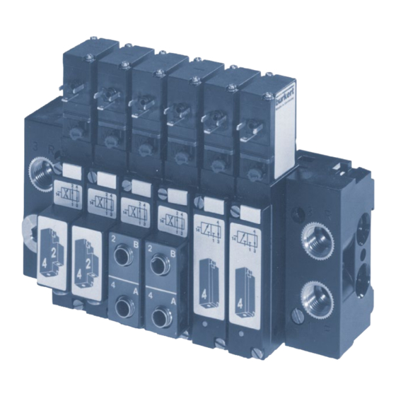
Modular valve island for pneumatics with width per station 19 mm
Hide thumbs
Also See for 8640:
- Operating instructions manual (196 pages) ,
- Quick start manual (21 pages) ,
- Operating instructions manual (26 pages)

Related Manuals for Burkert 8640


Summary of Contents for Burkert 8640
- Page 1 Type 8640 Modular valve island for pneumatics with width per station 19 mm Operating instructions...
- Page 2 We reserve the right to make technical changes without notice. Technische Änderungen vorbehalten. Sous réserve de modifications techniques. © Bürkert Werke GmbH & Co. KG, 2024 Operating Instructions 2402/11_EUen_00803136 / Original DE...
-
Page 3: Table Of Contents
Type 5470 Contents Single valve installation ..........14 OPERATING INSTRUCTIONS ..........4 Symbols ................ 4 INSTALLATION ..............15 Definition of terms ............4 Pneumatic installation ..........15 Electrical installation ........... 16 INTENDED USE ..............5 START-UP ................17 BASIC SAFETY INSTRUCTIONS ........... 5 10 MAINTENANCE, TROUBLESHOOTING ...... -
Page 4: Operating Instructions
Definition of terms these instructions. Term Definition for these instructions Symbols Device Valve island type 8640 DANGER! Warns of an immediate danger. ▶ Failure to observe will result in death or serious injuries. WARNING! Warns of a potential danger. ▶ Failure to observe these warnings may result in serious injuries or death. -
Page 5: Intended Use
BASIC SAFETY INSTRUCTIONS These safety instructions do not take into account any coinci- The valve island type 8640 with valves of type 5470 is dences or events occurring during installation, operation and designed to control neutral media and compressed air. - Page 6 Type 5470 Basic safety instructions General hazardous situations. NOTE! To prevent injuries, observe the following: Electrostatically sensitive components and assemblies. ▶ Observe the general rules of technology. The device contains electronic components that are susceptible ▶ In the potentially explosive atmosphere, only use devices that to the effects of electrostatic discharging (ESD).
-
Page 7: General Notes
Email: info@burkert.com International Contact addresses can be found on the final pages of the printed operating instructions. They are also available online at: https://country.burkert.com. Information online Operating instructions and data sheets for Bürkert products can Fig. 1: Structure of solenoid valve type 5470... -
Page 8: Description
Type 5470 Structure and description 5.1.1 Manual override 5.1.2 Connections The connections are marked with numbers for better assignment. → To operate the valve manually, press the manual override and turn it 90° clockwise (until it stops). The manual override is Connection number Designation locked and does not reset automatically. -
Page 9: Circuit Functions
Type 5470 Structure and description Circuit functions Conversion of 4/2 to a 3/2-way valve C, 3/2-way valve 2(A) In rest position, pressure port 1 (P/NC) closed, working port 2 (A/OUT) open 1(P) 3(R) after port 3 (R/NO). D, 3/2-way valve 2(B) In rest position, pressure port 1 (P/NO) ope after working port 2 (B/OUT), port... -
Page 10: Technical Data
Type 5470 Structure and description TECHNICAL DATA Electrical data Conformity Electrical connection Cable plug Type 2516 on the plug con- tacts of the coil (torque for fastening: 1 The device conforms to EU directives as per the EU Declaration Nm). of Conformity. -
Page 11: Type Label
Type 5470 Structure and description INSTALLATION Type label DANGER! 5470 G1/8 PN2–10bar Risk of injury due to high pressure and escaping medium. ▶ Switch off the pressure before working on the device or sys- tem. Vent or drain the pipes. 00203236 00203236 W1YMG... -
Page 12: Rotating The Solenoid
Type 5470 Structure and description Prior to installation → Clean the pipes. → If necessary, attach dirt trap upstream. → Do not use the coil as a lever when screwing in the Coil rotation connections. by 180° Rotating the solenoid CAUTION! Danger of electric shock if the coil is installed incorrectly. -
Page 13: Installing Multiple Blocks
Type 5470 Structure and description Installing multiple blocks → Begin installation with connection module on the left (see “Fig. 6”) → Check modules for complete installation with 2 O-rings each. → Lightly oil or grease all O-rings before engaging. → Engage the lower latch hooks of the module to be attached in the latch grooves of the preceding module. -
Page 14: Valve Block Installation
Type 5470 Structure and description Valve block installation Wall installation → Fasten the valve block directly to the wall with M4 screws Single valve installation → Fasten single valves directly to the wall with M4 screws (see “Fig. 8”). Fig. 7: Mounting the valve block Item Designation Electrical connection can be rotated by 180°... -
Page 15: Installation
Type 5470 Structure and description INSTALLATION Before connection → Check the hose lines for contamination and clean them. WARNING! → If necessary, install dirt traps upstream of the valve inlet (≤ 5 Risk of injury due to improper installation µm). ▶... -
Page 16: Electrical Installation
Type 5470 Structure and description Electrical installation Item Designation Seal DANGER! Approved cable plug, e.g. Type 2516 or other according Risk of injury due to electric shock. to DIN ISO 175301-803 Form C ▶ Switch off voltage before working on the device or system. →... -
Page 17: Start-Up
Type 5470 Structure and description START-UP 8.2.2 Impulse design control unit NOTE! WARNING! The correct polarity is a prerequisite to ensuring that the device functions. Note the label on the surface of the coil. Risk of injury due to improper operation. Pulse duration at least 50 ms. -
Page 18: Maintenance, Troubleshooting
Type 5470 Maintenance, troubleshooting MAINTENANCE, Fault Possible cause Remedy TROUBLESHOOTING Valves Pressure supply insuf- Set up large-volume switch with ficient or not available pressure supply (also for WARNING! a delay upstream devices such or blow as pressure controllers, Risk of injury if maintenance work is not carried out correctly. off at the maintenance units, on/off ▶... -
Page 19: Disassembly
Type 5470 Maintenance, troubleshooting DISASSEMBLY RIGHT CONNECTION MODULE Other application options: WARNING! • Connection modules on the right can be used in special appli- Risk of injury due to high pressure and escaping medium. cations as sub-modules to build up several operating pressure ▶... - Page 20 www.burkert.com...
Need help?
Do you have a question about the 8640 and is the answer not in the manual?
Questions and answers