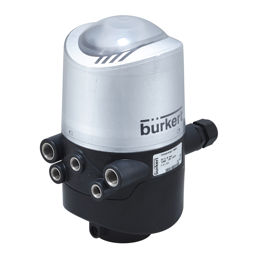
Burkert 8681 Quick Start Manual
Control head
Hide thumbs
Also See for 8681:
- Operating instructions manual (166 pages) ,
- Quick start manual (92 pages) ,
- Conversion instructions (31 pages)
Advertisement
Available languages
Available languages
Quick Links
Download this manual
See also:
Quick Start Manual
We reserve the right to make
technical changes without notice.
Technische Änderungen
vorbehalten.
Sous réserve de modifi cations
techniques.
www.burkert.com
© 2010 - 2011 Bürkert Werke GmbH
Operating Instructions 1105/02_EU-ml_00806166 / Original DE
1.
THE QUICKSTART
WARNING!
Important safety information!
Read quickstart carefully and thoroughly. Study in par-
ticular the chapters entitled 4. Basic Safety Instructions
and 3. Authorized use .
•
The operating instructions must be read and understood.
Quickstart explains, for example, how to install and start-up
the device.
The detailed description of the device can be found in the
operating instructions for Control Head Type 8681.
The operating instructions can be found on the
Internet at:
www.burkert.com
english
2
Documentation
Type 8681
Type 8681
Control Head
Steuerkopf
Tête de commande
Quickstart
2.
SYMBOLS
The following symbols are used in these instructions.
DANGER!
Warns of an immediate danger!
•
Failure to observe the warning will result in a fatal or
serious injury.
WARNING!
Warns of a potentially dangerous situation!
•
Failure to observe the warning may result in serious
injuries or death.
CAUTION!
Warns of a possible danger!
•
Failure to observe this warning may result in a moderate
or minor injury.
NOTE!
Warns of damage to property!
Important tips and recommendations for safe and
the fl awless functioning of the device.
designates a procedure which you must carry out.
english
3
Advertisement

Subscribe to Our Youtube Channel
Related Manuals for Burkert 8681


Summary of Contents for Burkert 8681
- Page 1 The detailed description of the device can be found in the CAUTION! operating instructions for Control Head Type 8681. Warns of a possible danger! The operating instructions can be found on the Internet at: •...
- Page 2 3.1. Predictable Misuse • Do not supply the medium connectors of the system with Non-authorized use of the Control Head Type 8681 aggressive or fl ammable media. may be a hazard to people, nearby equipment and • Do not supply the medium connectors with any liquids.
- Page 3 GENERAL INFORMATION STRUCTURE AND FUNCTION The Control Head Type 8681 has been designed for use 5.1. Scope of Supply as actuation of pneumatically operated process valves and/ Check immediately upon receipt of the delivery that the con- or for recording the switching states of these.
- Page 4 Type 8681 6.2. Structure TECHNICAL DATA 7.1. Operating Conditions Position measuring system with LED’s Ambient temperature: -10 ... +55 °C Flow restriction Electronics module (24VDC- or AS-i- screw(s) of Protection class: IP65 / IP67 according to EN 60529 or solenoid valves...
- Page 5 Assembly A silencer has already been mounted on the Exhaust Air Connection (3/R) in the supplied state. For the installation of the Control Head Type 8681 to a process valve, you will require a process valve-specifi c hub Sealing lugs fl...
- Page 6 Type 8681 9.2. Electrical Data Input / proximity switches (external initiator: S4 in): Power supply: Voltage present at control head - 10 % Power supply: 12 ... 28 V DC, residual ripple 10 % Current carrying Power consumption: capacity, sensor...
- Page 7 Type 8681 Cable gland with Multi-pole connection: Input and output signals to the higher-level control (PLC): Internal cabling work is not required for models with multi-pole Pin 3 - S1 out Pin 2 - GND connection. But you will require the correspondingly...
- Page 8 Type 8681 Current carrying capacity, External Power Supply: sensor power supply: max. 30 mA; Ext. power supply: 19.2 V DC to 31.6 V DC short-circuit protection Max. power consumption from external power supply: 110 mA at 24 V DC...
- Page 9 Type 8681 Process data 2 static input assemblies Baud rate Thick Cable Thin Cable (Input: from the control head to the 500 m 100 m DeviceNet Master/Scanner) 250 m 100 m 1 static output assembly 100 m 100 m Inputs...
- Page 10 Type 8681 11.6. Network Topology View of plug from the front onto the pins: When installing a DeviceNet system, ensure that the termi- Pin 3: V– Pin 4: CAN_H nating circuit of the data lines is correct. The circuit prevents the occurrence of interference caused by signals refl...
- Page 11 Type 8681 120 V AC - DESIGN Central display of the switching states: 13 mA with a power supply of 12.1. Connection 120 V AC per illuminated display Outputs/binary left connection: feedback signals: S1out - S3out 1 x M16 x 1,5 cable gland for...
- Page 12 Close the housing. plant / the device in operation. 13.2. Teach-Reset Assembly of the control head type 8681. Depress the Teach-In button ( T1+T2) for ca. 2.5 sec. (optical feedback: Blinking in the fault color) Pneumatic and electrical installation.
- Page 13 Type 8681 PACKAGING, TRANSPORT, STORAGE, DISPOSAL NOTE! Transport / storage damage! Inadequately protected equipment may be damaged during transport or storage. • Protect the device during transportation / storage against moisture and dirt in shock-resistant packaging. • Avoid the effects of heat and cold which could result in temperatures above or below the permitted storage temperature.
- Page 14 • Bei Nichtbeachtung können schwere Verletzungen oder Die ausführliche Beschreibung des Gerätes fi nden Sie in Tod die Folge sein. der Bedienungsanleitung für den Typ 8681. VORSICHT! Die Bedienungsanleitung fi nden Sie im Internet: Warnt vor einer möglichen Gefährdung! www.buerkert.de...
- Page 15 • Verwenden Sie für den Anschluss des Steuerkopfes Bei nicht bestimmungsgemäßem Einsatz des Leitungsinstallationen, die keine unzulässigen mecha- Steuerkopfes Typ 8681 können Gefahren für Per- nischen Belastungen verursachen. sonen, Anlagen in der Umgebung und die Umwelt • Setzen Sie das Gerät nur bestimmungsgemäß ein.
- Page 16 Gewährleistung auf Geräte und Zubehörteile! deutsch deutsch ALLGEMEINE HINWEISE AUFBAU UND FUNKTION Der Steuerkopf Typ 8681 ist konzipiert für den Einsatz als 5.1. Lieferumfang Ansteuerung pneumatisch betätigter Prozessventile und / Überzeugen Sie sich unmittelbar nach Erhalt der Sendung, oder für die Erfassung von deren Schaltzuständen.
- Page 17 Typ 8681 6.2. Aufbau TECHNISCHE DATEN 7.1. Betriebsbedingungen Wegmesssystem mit LED‘s Umgebungstemperatur: -10 ... +55 °C Drossel- Elektronikmodul (24VDC- oder schrauben der Schutzart: IP65 / IP67 nach EN 60529 bzw. Magnetventile AS-i-Ausführung mit IP69K nach IEC 40050-9 Serviceschnittstelle, Klemmleisten, DIP, 7.2.
- Page 18 8.1. Montage Am Abluftanschluss (3/R) ist im Lieferzustand bereits ein Schalldämpfer montiert. Zur Montage des Steuerkopfes Typ 8681 an ein Prozess- ventil benötigen Sie einen prozessventilspezifi schen Auf- Verplombungs- nahmefl ansch als Adapter. Der Aufnahmefl ansch muss der nasen Bauform des Prozessventiles angepasst sein.
- Page 19 Typ 8681 9.2. Elektrische Daten Eingang/Näherungsschalter (externer Initiator: S4 in): Spannungs- angelegte Spannung am Spannungs- versorgung: Steuerkopf - 10 % versorgung: 12 ... 28 V DC, Restwelligkeit 10 % Strombelastbarkeit Stromaufnahme Sensorversorgung: max. 90 mA; Kurzschlussschutz (Ruhestrom): 30 mA bei 24 V DC Bauart: DC 2- und 3-Draht, NO od.
- Page 20 Typ 8681 Kabelverschraubung mit Multipolanschluss: Ein- und Ausgangssignale zur übergeordneten Steuerung (SPS): Bei Varianten mit Multipolanschluss sind keine internen Verkabelungsarbeiten notwendig. Sie benötigen allerdings Pin 3 - S1 out Pin 2 - GND entsprechend konfektionierte bzw. montierte Kabelsätze mit folgender Pin-Belegung:...
- Page 21 Typ 8681 Bauart: DC 2- und 3-Draht, NO od. NC; 10.5. Elektrische Installation (AS-i) PNP-Ausgang WARNUNG! Eingänge: 3 binäre Rückmeldesignale und (aus Mastersicht) 1 x externer Initiator Verletzungsgefahr durch Stromschlag! • Vor Eingriffen ins System (außer Teach-In-Vorgang in Ausgänge: 0 bis 3 Magnetventile Nicht-Ex-Atmosphäre) die Spannung abschalten, vor...
- Page 22 Typ 8681 Prozessdaten 2 statische Input-Assemblies Baudrate Dickes Kabel Dünnes Kabel (Input: vom Steuerkopf zum 500 m 100 m DeviceNet-Master/Scanner) 250 m 100 m 1 statisches Output-Assembly 100 m 100 m Eingänge 3 diskrete Rückmeldesignale des Weg messsystems (Positionen S1 - S3) Die maximale Stichleitungslänge (Drop Line) beträgt für:...
- Page 23 Typ 8681 11.6. Netztopologie Steckeransicht von vorn auf die Stifte: Bei der Installation eines DeviceNet-Systems ist auf die kor- Pin 3: V– Pin 4: CAN_H rekte Abschlussbeschaltung der Datenleitungen zu achten. Die Beschaltung verhindert die Entstehung von Störungen Pin 5: CAN_L durch Signalrefl...
- Page 24 Typ 8681 Zentrale Anzeige der Schaltzustände: 120 V AC - AUSFÜHRUNG 13 mA bei Spannungsver- 12.1. Anschlussmöglichkeit sorgung 120 V AC je darge- stellter Leuchtanzeige linker Anschluss: Ausgänge/binäre 1 x M16 x 1,5 Kabelverschraubung Rückmeldesignale: S1out - S3out für Spannungsversorgung und Bauart: Schließer (NO), L-schaltend,...
- Page 25 Teach-In-Tasten (T1 + T2) ca. 2,5 s gedrückt halten das Gerät in Betrieb nehmen. (optische Rückmeldung: Blinken in Fehlerfarbe) 13.3. Autotune Montage des Steuerkopfs 8681. Autotune-Funktionen und Autotune-Ablauf - siehe Pneumatische und elektrische Installation. Bedienungsanleitung Einstellen des Wegmesssystems (Teach-In).
- Page 26 Typ 8681 VERPACKUNG, TRANSPORT, LAGERUNG, ENTSORGUNG HINWEIS! Lagerungs- / Transportschäden! Unzureichend geschützte Geräte können durch Transport oder Lagerung beschädigt werden. • Gerät vor Nässe und Schmutz geschützt in einer stoß- festen Verpackung transportieren/lagern. • Eine Über- bzw. Unterschreitung der zulässigen Lager- temperatur vermeiden.
- Page 27 Risque de blessures graves, voire la mort en cas de mise en service de l‘appareil. non-respect. Vous trouverez la description détaillée dans le instructions de service du type 8681 «Tête de commande» ATTENTION ! Met en garde contre un risque possible ! •...
- Page 28 L’utilisation non conforme de la tête de commande non admissibles. type 8681 peut présenter des dangers pour les per- • Veillez à ce que l’utilisation de l’appareil soit toujours sonnes, les installations proches et l’environnement.
- Page 29 ! français français INDICATIONS GÉNÉRALES DESCRIPTION DU SYSTÈME La tête de commande type 8681 est conçue pour être 5.1. Fourniture utilisée comme commande des vannes de process Dès réception de l’envoi, assurez-vous que le contenu n’est pneumatiques et/ou pour la détection de leurs états de...
- Page 30 Type 8681 6.2. Structure CARACTÉRISTIQUES TECHNIQUES Système de mesure de déplacement avec LED tricolores 7.1. Conditions d’exploitation Module électronique (version 24 V DC ou Vis-pointeau(x) Température ambiante : -10 ... +55 °C AS-i avec interface de pour P et R service, bornes de (2 par électro-...
- Page 31 Type 8681 MONTAGE/INSTALLATION 8.1. Montage Le montage de la tête de commande type 8681 sur une DANGER ! vanne de process nécessite une bride support spécifi que à la vanne de process en tant qu’adaptateur. La bride support Danger dû à la haute pression ! doit être adaptée à...
- Page 32 Type 8681 9.2. Caractéristiques électriques VERSION 24 V DC Alimentation en tension : 12 ... 28 V DC, ondulation 9.1. Possibilités de raccordement résiduelle 10 % Courant absorbé (courant de repos): 30 mA pour 24 V DC Électrovannes : Puissance absorbée par électrovanne :...
- Page 33 Type 8681 Fixer les fi ls aux bornes de raccordement conformément Borne plate 1 Affectation aux affectations de raccordement décrites dans la fi gure : 24 V Alimentation en tension 24 V Interface Touches Teach-In T1-3 service S1 OUT...
- Page 34 Type 8681 10. VERSION AS-I 10.3. Longueur maximale du câble 10.1. Possibilités de raccordement La longueur maximale du câble bus est de 100 m. Lors du dimensionnement de l’installation, il convient de tenir compte de la longueur du câble rond menant directement à la tête de commande (voir l’exemple de calcul en l’instructions de...
- Page 35 Type 8681 Les versions d’AS Interface avec raccord multipolaire sur le VERSION DEVICENET câble ne nécessitent pas de travaux de câblage internes. Vous 11.1. Possibilité de raccordement avez cependant besoin des jeux de câbles confectionnés resp. montés avec les affectations des broches suivantes.
- Page 36 Type 8681 Capacité de courant de l’alimentation Affi chage centralisé des états de commutation : Courant absorbé depuis DeviceNet des capteurs : 30 mA maxi Protection contre les courts-circuits avec 24 V DC : 42 mA avec alimentation en tension...
- Page 37 Type 8681 11.8. Confi guration des données «Adresse» dans le tableau c’est l’adresse attribut de données des ensembles pour l’accès en lecture: de process Class, Instance, Attribute. 2 ensembles d’entrées statiques et 1 ensemble de sorties Adresse Format de l’attribut de données statiques sont disponibles pour la transmission des données...
- Page 38 Type 8681 Construction : DC 2 et 3 fi ls, contact de fermeture AVERTISSEMENT ! (NO), commutation à gauche Courant d’entrée Risque de blessures dû à un montage non signal 1 : < 2 mA conforme ! capteur • La terre de protection PE doit être raccordée !
- Page 39 Respectez les consignes de sécurité et l’utilisation conforme. • L’appareil/l’installation doit être mis(e) en service uni- quement par un personnel suffi samment formé. Montage de la tête de commande type 8681. Installation pneumatique et électrique. Réglage du système de mesure de déplacement (Teach-In).
- Page 40 Type 8681 EMBALLAGE, TRANSPORT, STOCKAGE, ELIMINATION REMARQUE ! Dommages dus au transport et stockage! Les appareils insuffi samment protégés peuvent être endommagés pendant le transport ou stockage. • Transportez / stockez l’appareil à l’abri de l’humidité et des impuretés et dans un emballage résistant aux chocs.
Need help?
Do you have a question about the 8681 and is the answer not in the manual?
Questions and answers