Table of Contents
Advertisement
Quick Links
NOTICE: This bulletin is also applicable to Kyle product
serial numbers beginning with the prefix CP57.
Reclosers
Kyle
®
Form 5/Triple-Single
Microprocessor-Based Recloser Control
Installation and Operation Instructions
Applicable to Serial Numbers 9416 and above.
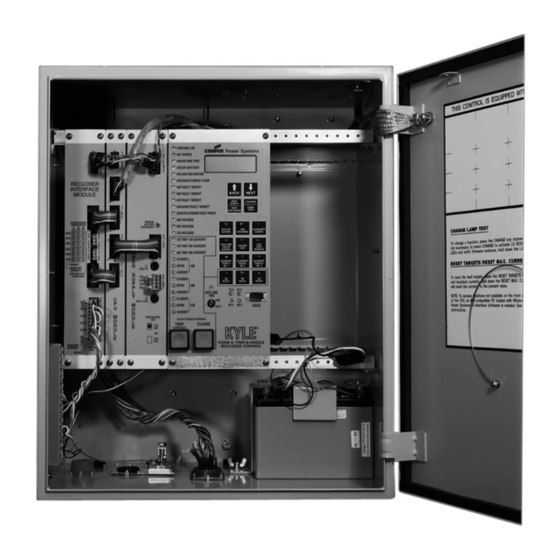
Figure 1.
Kyle
®
Form 5/Triple-Single microprocessor-based recloser control.
Contents
Safety Information . . . . . . . . . . . . . . . . . . . . . . . . . 2
Product Information . . . . . . . . . . . . . . . . . . . . . . . . 3
Introduction . . . . . . . . . . . . . . . . . . . . . . . . . . . . . . . 3
ANSI Standards . . . . . . . . . . . . . . . . . . . . . . . . . . . 3
Quality Standards . . . . . . . . . . . . . . . . . . . . . . . . . . 3
Acceptance and Initial Inspection . . . . . . . . . . . . . . 3
Handling and Storage . . . . . . . . . . . . . . . . . . . . . . . 3
Battery Replacement . . . . . . . . . . . . . . . . . . . . . . . 3
Battery Disposal . . . . . . . . . . . . . . . . . . . . . . . . . . . 3
Control Power . . . . . . . . . . . . . . . . . . . . . . . . . . . . . 3
Initializing the Control . . . . . . . . . . . . . . . . . . . . . . . 4
Phase Operation . . . . . . . . . . . . . . . . . . . . . . . . . . . 5
Ground Operation . . . . . . . . . . . . . . . . . . . . . . . . . . 5
Sensitive Ground/Earth Fault Operation . . . . . . . . . 6
Central Processing Unit (CPU) Module . . . . . . . . . 6
Discrete Interface (DIF) Module . . . . . . . . . . . . . . . 6
Power Supply Module . . . . . . . . . . . . . . . . . . . . . . . 6
Triple-Single Control Operator Panel . . . . . . . . . . . 7
Control Features . . . . . . . . . . . . . . . . . . . . . . . . . . . 15
Communications . . . . . . . . . . . . . . . . . . . . . . . . . . . 20
Auxiliary Power for Accessories . . . . . . . . . . . . . . 21
March 2003 • Supersedes 7/01
Printed in USA
. . . . . . 5
. . . . . . . . . . . . . . 6
. . . . . . . . . . . . . . . . . . . 15
S280-42-3
(UDP) Control . . . . . . . . . . . . . . . . . . . . . . . . . . . . . 22
Discrete Interface (DIF) Accessory . . . . . . . . . . . . 23
Customer Connection Information . . . . . . . . . . . . . 23
Standard and UDP DIF Module 1 Inputs . . . . . . . . 26
Standard and UDP DIF Module 1 Outputs . . . . . . . 27
Standard and UDP Module 2 Inputs . . . . . . . . . . . . 28
Standard and UDP Module 2 Outputs . . . . . . . . . . 29
Input Accuracy . . . . . . . . . . . . . . . . . . . . . . . . . . . . 30
Installation Procedure . . . . . . . . . . . . . . . . . . . . . . 31
Initial Programming Prior to Installation . . . . . . . . . 31
Control Cable . . . . . . . . . . . . . . . . . . . . . . . . . . . . . 31
Triple-Single Control Junction Box . . . . . . . . . . . . . 31
Mounting the Control . . . . . . . . . . . . . . . . . . . . . . . 32
Grounding the Control . . . . . . . . . . . . . . . . . . . . . . 33
Customer Connections for AC Power . . . . . . . . . . . 37
Customer Connections for Metering . . . . . . . . . . . . 37
Testing . . . . . . . . . . . . . . . . . . . . . . . . . . . . . . . . . . . 41
Testing an Installed Control . . . . . . . . . . . . . . . . . . 41
Electrical Testing of NOVA-TS Reclosers . . . . . . . 42
Battery Test Procedure . . . . . . . . . . . . . . . . . . . . . . 43
Return the Control to Service . . . . . . . . . . . . . . . . . 44
Additional Information . . . . . . . . . . . . . . . . . . . . . . 44
Service Information
99015KM
. . . . . . . . . . . . . 42
1
Advertisement
Table of Contents

Related Manuals for Cooper Kyle Form 5/Triple-Single


Summary of Contents for Cooper Kyle Form 5/Triple-Single
-
Page 1: Table Of Contents
NOTICE: This bulletin is also applicable to Kyle product serial numbers beginning with the prefix CP57. Reclosers Kyle ® Form 5/Triple-Single Service Information Microprocessor-Based Recloser Control S280-42-3 Installation and Operation Instructions Applicable to Serial Numbers 9416 and above. 99015KM Figure 1. Kyle ®... -
Page 2: Safety Information
FOR LIFE FOR LIFE Cooper Power Systems products meet or exceed all applicable industry standards relating to product safety. We actively promote safe practices in the use and maintenance of our products through our service literature, instructional training programs, and the continuous efforts of all Cooper Power Systems employees involved in product design, manufacture, marketing, and service. -
Page 3: Product Information
Temperature has an effect on battery life. Sealed lead ered sufficiently for the user's purpose, contact your acid batteries should be stored, fully-charged, at room Cooper Power Systems sales representative. temperature. Never store lead acid batteries at tempera- ture exceeding 47°C (117°F), as damage can result in ANSI Standards approximately one month. -
Page 4: Control Power
Kyle Form 5/Triple-Single Microprocessor-Based Recloser Control Installation and Operation Instructions Control Power The primary source of power is factory configured for 120 Vac or 240 Vac. Primary power is rectified to charge the power capacitor and to power the dc/dc converter that provides power to the control. -
Page 5: Form 5/Triple-Single Control Description
S280-42-3 SAFETY FOR LIFE FORM 5/TRIPLE-SINGLE CONTROL DESCRIPTION The Kyle Form 5/Triple-Single microprocessor-based incorporates a Central Processing Unit (CPU) module, recloser control is designed for use with the Kyle NOVA- power supply module, Recloser Interface (RIF) module, TS Triple-Single reclosers to provide automation of distri- and an operator panel. -
Page 6: Sensitive Ground/Earth Fault Operation
Kyle Form 5/Triple-Single Microprocessor-Based Recloser Control Installation and Operation Instructions Sensitive Ground/Earth Fault 16-bit analog-to-digital converter. The CPU module accepts 16 analog inputs which it routes through the digi- Operation tal signal processor, which samples 32 times per cycle, to Sensitive Ground/Earth Fault (SGF/SEF) is active when compute harmonic analysis to the 15th harmonic. -
Page 7: Triple-Single Control Operator Panel
S280-42-3 SAFETY FOR LIFE Form 5/Triple-Single Control AC POWER Operator Panel This green LED is illuminated when the presence of ac input power to the control is sensed. The LED will turn off The Form 5/Triple-Single control operator panel (Figure 5) if ac power is lost for more than 15 seconds. - Page 8 Kyle Form 5/Triple-Single Microprocessor-Based Recloser Control Installation and Operation Instructions AØ VOLTAGE TRIP (Lockout) Pushbutton BØ VOLTAGE The TRIP pushbutton (Figure 6) provides front-panel access to trip (lockout) the recloser. When pressed, the CØ VOLTAGE TRIP push-button manually opens the recloser and locks These red voltage LEDs illuminate when the control out the control.
- Page 9 S280-42-3 SAFETY FOR LIFE RS232 Communication Port NEXT Key The standard Form 5/Triple-Single control is equipped Pressing the NEXT key causes the LCD display to scroll with an operator panel RS232 port for interface with a per- to the next screen of available information. Pressing and sonal computer running the Form 5/Triple-Single interface holding the NEXT key causes the control to scroll to sub- software program.
- Page 10 Kyle Form 5/Triple-Single Microprocessor-Based Recloser Control Installation and Operation Instructions LCD Display Screens Screen 6 - S1 Phase-to-Neutral, Instant. Voltage Every screen contains a parameter name, parameter 6 Instant S1 Ph-N value, and parameter units. If the control detects that a...
- Page 11 S280-42-3 SAFETY FOR LIFE Screen 12 - Instantaneous kVA Screen 18 - Demand Phase-to-Phase Voltage 12 Tot ____________ kVA 18 Demand S1 Ph-Ph Ph1-2 ____________ kVA Ph1-3 (d) ____________ V Ph3-4 ____________ kVA Ph3-5(d) ____________ V Ph5-6 ____________ kVA Ph5-1(d) ____________ V Screen 13 - Instantaneous kVAR Screen 19 - Demand Phase-to-Neutral Voltage...
- Page 12 Kyle Form 5/Triple-Single Microprocessor-Based Recloser Control Installation and Operation Instructions Screen 24 - Demand kVA Screen 31 - Battery Monitor The Battery Monitor displays the battery voltage, current, 24 Tot ____________ kVA and voltage during a battery test. The Battery Monitor is...
- Page 13 S280-42-3 SAFETY FOR LIFE Screen 41 - Communication Port 3 Settings Screen 36 -Ground Min, Phase 1-2 Min Demand Currents This message displays the protocol settings (2179 or DNP3.0), baud rate, and address for Serial Port #3. 36 Gnd Min ____________A Baud rate and address are set using the interface soft- Time...
- Page 14 Kyle Form 5/Triple-Single Microprocessor-Based Recloser Control Installation and Operation Instructions SUPERVISORY BLOCKED HOT LINE TAG ON/OFF Toggle Switch and LED Indicator SUPERVISORY BLOCKED disables supervisory SCADA and interface software; remote SCADA remains active. Operational data and metering information are available WARNING: Hazardous voltage.
-
Page 15: Manual Control Operation
S280-42-3 SAFETY FOR LIFE Manual Control Operation 1Ø Trip – 1Ø Lockout (Mode C) When in Single-Phase Trip – Single-Phase Lockout Each single-phase unit in the NOVA-TS Triple-Single (Mode C) any combination of phases can be selected and recloser represents either A, B, or C phase. Phase selection the respective PHASE SELECT LED illuminates. - Page 16 Kyle Form 5/Triple-Single Microprocessor-Based Recloser Control Installation and Operation Instructions Voltage Protection (120 Vac-based) Trip Failure Detection Voltage protection functionality is included as standard on The Trip Failure Detection feature is an internal diagnos- Form 5/Triple-Single controls. A recloser trip is issued for...
- Page 17 S280-42-3 SAFETY FOR LIFE The Trip Failure Detection alarm may be triggered from Fast Trips Disabled many potential sources including mechanical, electrical, Fast Trips Disabled provides the user a quick and efficient control, or interrupter failure. Interrupter failure may method for reducing momentary interruptions or “blinks”. include loss of vacuum in a vacuum interrupter.
- Page 18 Kyle Form 5/Triple-Single Microprocessor-Based Recloser Control Installation and Operation Instructions Data Profiler Status alarms are included for Modes A, B, and C as well as the following status alarms for each phase of the Kyle A fully-configurable data profiler is available which allows...
- Page 19 S280-42-3 SAFETY FOR LIFE The following system parameters must be entered via the Torque Angle Width parameter restricts the tripping to an Protection Profile menu for each profile: angle of plus or minus the specified width about the Torque angle setting. For example, if the Maximum •...
-
Page 20: Communications
Kyle Form 5/Triple-Single Microprocessor-Based Recloser Control Installation and Operation Instructions Communications The RS-232 accessory board and the fiber-optic acces- sory boards are located behind the operator panel. Each Communication Ports accessory board can be connected to either Port 2 or Port 3;... -
Page 21: Auxiliary Power For Accessories
S280-42-3 SAFETY FOR LIFE AUXILIARY POWER FOR RECLOSER INTERFACE (RIF) ACCESSORIES MODULE CONFIGURATION Connection P9 (Figure 20) on the Power Supply module CAUTION: Equipment damage. Always wear a ground- provides 28Vdc (12Vdc is available) to power radio com- ing wrist strap to control static electricity before handling munication units, RTUs and other accessories. -
Page 22: Form 5/Triple-Single Universal Device Protection (Udp) Control
Kyle Form 5/Triple-Single Microprocessor-Based Recloser Control Installation and Operation Instructions FORM 5/TRIPLE-SINGLE UNIVERSAL DEVICE PROTECTION (UDP) CONTROL The UDP function allows the Form 5/Triple-Single control to become a switch control to provide indication of over- current trip conditions without issuing an overcurrent trip signal. -
Page 23: Discrete Interface (Dif) Accessory
S280-42-3 SAFETY FOR LIFE DISCRETE INTERFACE (DIF) ACCESSORY INPUT COMMON 28V (-) WHETTING 28V (+) VOLTAGE OUTPUT COMMON The Discrete Interface (DIF) module accessory (Figure 25) permits connection of contact-type input devices (switches, relays) and discrete indicating devices (relays, LEDs, lamps) to the Form 5/Triple-Single control to effect local discrete input/output (I/O). - Page 24 Kyle Form 5/Triple-Single Microprocessor-Based Recloser Control Installation and Operation Instructions FORM 5 CONTROL *28Vdc (nominal) Remote Terminal Unit (RTU) supplied by INPUT COMMON DIF module for whetting voltage. 28V (-) 28V (+) OUTPUT COMMON COMMON* SUPERVISORY BLOCK NORMAL PROFILE HOT LINE TAG...
- Page 25 S280-42-3 SAFETY FOR LIFE TABLE 1 DIF Input Ratings Minimum detection level: ......8 Vac (50 or 60Hz) 10 Vdc Maximum Operating Voltage: .
-
Page 26: Standard And Udp Dif Module 1 Inputs
Kyle Form 5/Triple-Single Microprocessor-Based Recloser Control Installation and Operation Instructions Form 5/Triple-Single and Form 5/Triple-Single UDP Control DIF Module 1 Inputs The DIF inputs are factory-configured as momentary (0.25 sec. duration) or maintained functions. When Supervisory is blocked, Supervisory signals are disabled, but Remote inputs are active. Whetting voltage for the DIF inputs is sup- plied by the DIF module or by the user. -
Page 27: Standard And Udp Dif Module 1 Outputs
S280-42-3 SAFETY FOR LIFE Form 5/Triple-Single and Form 5/Triple-Single UDP Control DIF Module 1 Outputs The 12 outputs of the DIF Module are Form C relay contacts. Six of the outputs are latching and six are non-latching. Note: Contacts shown in inactive mode. Output Connector Function Type... -
Page 28: Standard And Udp Module 2 Inputs
Kyle Form 5/Triple-Single Microprocessor-Based Recloser Control Installation and Operation Instructions Form 5/Triple-Single and Form 5/Triple-Single UDP Control DIF Module 2 Inputs The DIF inputs are factory-configured as momentary or maintained functions. When Supervisory is blocked, Supervi- sory signals are disabled, but Remote inputs are active. Whetting voltage for the DIF inputs is supplied by the DIF mod- ule or by the user. -
Page 29: Standard And Udp Module 2 Outputs
S280-42-3 SAFETY FOR LIFE Form 5/Triple-Single and Form 5/Triple-Single UDP Control DIF Module 2 Outputs The 12 outputs of the DIF Module are Form C relay contacts. Six of the outputs are latching and six are non-latching. Note: Contacts shown in inactive mode. Output Connector Function Type... -
Page 30: Input Accuracy
Kyle Form 5/Triple-Single Microprocessor-Based Recloser Control Installation and Operation Instructions INPUT ACCURACY Sensed Currents Sensed Source Voltages Phase Current — Individual Phase Currents: Three-phase voltages used in voltage, power and power- factor related calculations: Range: 1 A to 10,000 A for 500:1 CTs... -
Page 31: Installation Procedure
S280-42-3 SAFETY FOR LIFE INSTALLATION PROCEDURE Initial Programming Prior to Triple-Single Control Junction Installation The Type NOVA-TS Triple-Single recloser is connected to CAUTION: Equipment misoperation. Do not the Form 5/Triple-Single recloser control at a junction box. connect this control to an energized recloser until See Figure 28. -
Page 32: Mounting The Control
Kyle Form 5/Triple-Single Microprocessor-Based Recloser Control Installation and Operation Instructions Mounting the Control Limits on control cable length are determined by the max- imum distance between the control, junction box, and Mount the Form 5/Triple-Single recloser control in a con- NOVA-TS Triple-Single recloser: venient, accessible location. -
Page 33: Grounding The Control
S280-42-3 SAFETY FOR LIFE Grounding the Control Figure 30 illustrates grounding methods for 3-wire ungrounded and 4-wire multi-grounded systems with local supply voltage transformer. WARNING: Hazardous voltage. Recloser and Figure 31 illustrates grounding methods for 3-wire control must be solidly grounded. Follow all ungrounded and 4-wire multi-grounded systems with locally approved procedures and safety practices when remote supply voltage transformer. - Page 34 Kyle Form 5/Triple-Single Microprocessor-Based Recloser Control Installation and Operation Instructions Grounding with a Local Supply Voltage Transformer; 4-Wire Multi-Grounded, 3-Wire Ungrounded, or Impedance-Grounded Installation of the Form 5/Triple-Single control must 4-Wire Multi-Grounded Systems include the following: IMPORTANT: In pole-mounted applications, a •...
- Page 35 S280-42-3 SAFETY FOR LIFE Grounding with a Remote Supply Voltage Transformer; 4-wire Multi-Grounded, 3-Wire Ungrounded, or Impedance-Grounded Installation of a Form 5/Triple-Single control with a remote IMPORTANT: In pole-mounted applications, a supply voltage transformer must include the following: ground connection must be made between the •...
- Page 36 Kyle Form 5/Triple-Single Microprocessor-Based Recloser Control Installation and Operation Instructions Grounding on a 3-Wire Uni-grounded System Installation of a Form 5/Triple-Single control on a 3-wire Supply Voltage Form 5 Control Input Terminal uni-ground system must include the following: Block Transformer •...
-
Page 37: Customer Connections For Ac Power
S280-42-3 SAFETY FOR LIFE Customer Connections for AC Power CAUTION: Equipment damage. Do not drill con- nection holes into the top of the cabinet. Connec- tion holes in the top of the cabinet will allow moisture to seep into the control and damage the components or cause control misoperation. - Page 38 Kyle Form 5/Triple-Single Microprocessor-Based Recloser Control Installation and Operation Instructions To insert wire: (Top View) 1. Insert 3/32 inch flat- AØ blade screwdriver into 240Vac CLOSING OPTION Wire Release and Locking hole. Y' VOLTAGE 120Vac CLOSING 2. Carefully insert the...
- Page 39 S280-42-3 SAFETY FOR LIFE AØ 240V CLOSING OPTION BØ CØ ZØ YØ CUSTOMER SOURCE 2 XØ CONNECTIONS POWER OUTPUT POWER VOLTAGE SOURCE OUTPUT OUTPUT VOLTAGE CØ *CØ BØ BØ CUSTOMER SOURCE 1 AØ *AØ CONNECTIONS POWER *REQUIRED FOR CONTROL OPERATION SEE POWER SUPPLY MODULE FOR CORRECT VOLTAGE...
- Page 40 Kyle Form 5/Triple-Single Microprocessor-Based Recloser Control Installation and Operation Instructions 240Vac CLOSING OPTION YØ VOLTAGE 120Vac CLOSING VOLTAGE BØ VOLTAGE 120Vac NEUTRAL BØ SOURCE 2 NEUTRAL GDC-3.15A SOURCE 1 CONFIGURED NEUTRAL ZØ CUSTOMER SOURCE 2 YØ CONNECTIONS POWER XØ OUTPUT...
-
Page 41: Before Placing Control And Recloser Into Service
S280-42-3 SAFETY FOR LIFE Before Placing the Control and TESTING the Recloser into Service CAUTION: Equipment misoperation. Do not CAUTION: Equipment misoperation. Do not connect this control to an energized recloser connect this control to an energized recloser until all control settings have been properly pro- until all control settings have been properly pro- grammed and verified. -
Page 42: Electrical Testing Of Nova-Ts Reclosers
Kyle Form 5/Triple-Single Microprocessor-Based Recloser Control Installation and Operation Instructions Remove the Control from Service IMPORTANT: Disconnect switches for ac sensing and power connections are necessary to isolate the Form 5/Triple-Single Recloser Control for testing and servicing. CPU Module LED Indicator 1. -
Page 43: Battery Test Procedure
S280-42-3 SAFETY FOR LIFE Battery Test Procedure Refer to Table 4 and follow this procedure to perform a bench test on a control battery in a service shop: The condition of the control battery is tested by depress- 1. Remove the control from service. Refer to Remove ing the BATTERY TEST key on the operator panel. -
Page 44: Return The Control To Service
Kyle Form 5/Triple-Single Microprocessor-Based Recloser Control Installation and Operation Instructions Return the Control to Service ADDITIONAL INFORMATION CAUTION: Equipment misoperation. Do not CAUTION: This equipment requires routine connect this control to an energized recloser inspection and maintenance to ensure proper until all control settings have been properly pro- operation.
Need help?
Do you have a question about the Kyle Form 5/Triple-Single and is the answer not in the manual?
Questions and answers