Advertisement
Quick Links
General Information
The LiteKeeper
logic board is shipped separately from the
®
enclosure to protect the components during shipping and
enclosure installation. Enclosure installation instructions
have been provided for the enclosure. Please refer to the
enclosure installation instructions for instructions on mount-
ing the enclosure as well as wiring loads to the relays. This
document discusses the mounting and connection of the
LiteKeeper
into the enclosure and assumes that this step
®
has been completed.
Getting Started
1. Do not discard these installation instructions. Please keep
for future reference and operation information.
2. It is recommended that all low voltage wiring be done with
power removed to the logic board to protect components
from potential shorts during the wiring process.
3. Use only as intended and at the listed voltage.
4. All installation and service must be performed by qualified
personnel or service technicians.
5. Install in accordance with the National Electrical Code
and any other codes which may apply.
6. Installation and wiring information contained in this docu-
ment is based on industry-accepted standards and prac-
tices. If conflicts exist between these instructions and any
applicable codes or ordinances, please contact Greengate
before proceeding with the installation.
7. High Voltage is present inside the enclosure. Use extreme
caution when performing maintenance on this equipment.
Failure to follow this warning and proper safety procedures
could result in severe injury or death, and/or damage to
the equipment.
8. Document all wiring and device terminations and loca-
tions so that devices can be properly configured and
programmed for operation.
Mounting in the Enclosure
The enclosure should have been mounted prior using the
installation instructions provided for this purpose. It is recom-
mended that the LiteKeeper
until all drilling is complete in the cabinet.
1. Remove all debris and metal shavings from the enclo-
sure.
2. Make certain that there is no high voltage wiring exposed
or in the space of the low voltage section of the enclo-
sure.
3. If you are using a 32 size enclosure, make certain that the
upper back plate is in place, securing the back plate with
the 1/4 turn screws as directed in the enclosure installa-
tion instructions.
Cooper Controls
Cooper Controls
203 Cooper Circle, Peachtree, GA 30269
203 Cooper Circle, Peachtree, GA 30269
800-553-3879
800-553-3879
www.coopercontrol.com
www.coopercontrol.com
LiteKeeper
not be put into the enclosure
®
(16/32)
®
4. Press and hold the two spring hinges on the back of the
logic board back plate towards the middle of the plate.
5. Making sure there are no cables caught beneath the logic
board, slide the logic board into the bottom of the enclosure
in the mounting space provided, lining the spring hinges up
with the mounting holes, releasing the spring hinges once
the logic board is in place.
6. Swivel the logic board up, using the spring hinge at the top
of the board to secure the board to the top of the enclosure
or upper back plate in the slot provided.
7. Connect the Relay Signal Ribbon Cable from the logic board
into the 40 pin connector on the Standard Override Card
(SOC).
CAN
CAN
J1
TX
RX
L1
L2
P1
L3
POWER
L4
L5
L6
L7
L8
L21
STATUS
L25
L26
L22
L23
L24
1
2
3
A
B
4
5
6
7
8
9
C
*
0
#
D
ON
+24
OFF
ON
+24
OFF
ON
+24
OFF
ON +24
OFF
ON
+24
OFF
ON
+24 OFF
ON
+24
VDC
VDC
VDC
VDC
VDC
VDC
VDC
CH17
CH18
CH19
CH20
CH21
CH22
CH23
CH1
CH2
CH3
CH4
CH5
CH6
CH7
ON
+24
OFF
ON
+24
OFF
ON
+24
OFF
ON +24
OFF
ON
+24
OFF
ON
+24 OFF
ON
+24
TB2
VDC
VDC
VDC
VDC
VDC
VDC
VDC
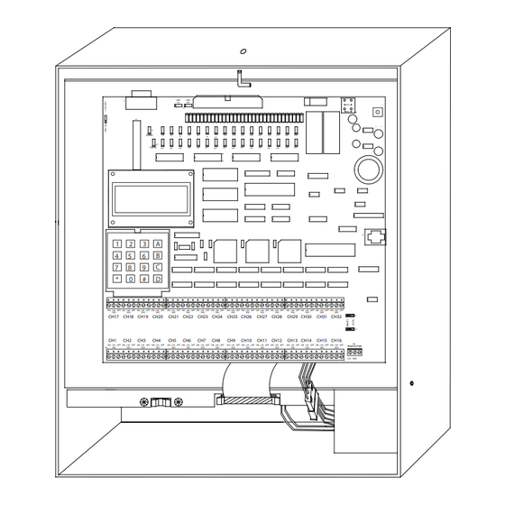
Figure-1: 16 size Enclosure with LK Mounted
Connecting Low Voltage Switches
The LiteKeeper
logic board can support a total of 64 switch
®
inputs. Of these 64 inputs, 32 of them may be dry contact
closure inputs that are connected to the terminal blocks at the
bottom of the LiteKeeper
may also be used on the LiteKeeper
switches are being used, the full 64 switch inputs may consist
of digital switches. If a combination of contact input switches
and digital switches are being used, the combined total cannot
exceed 64 inputs.
Regardless of switch type used, it is recommended that all
switch input wiring be done prior to applying power to the logic
board or at the very least with the terminal blocks removed
from the logic board.
InstAllAtIon sheet
Model#
lK lB
BLUE
RED
L11
L12
L13
L14
L15
L16
L17
L18
L19
L9
L10
L27
L29
L31
L33
L36
L37
L28
L30
L32
L34
L35
J4
OFF
ON +24
OFF
ON
+24
OFF ON
+24 OFF
ON
+24
OFF
ON +24
OFF
ON
+24
OFF ON
+24
OFF
ON
+24
OFF
ON
+24
OFF
VDC
VDC
VDC
VDC
VDC
VDC
VDC
VDC
VDC
CH24
CH25
CH26
CH27
CH28
CH29
CH30
CH31
CH32
J5
J6
CH8
CH9
CH10
CH11
CH12
CH13
CH14
CH15
CH16
TB3
OFF
ON +24
OFF
ON
+24
OFF ON
+24 OFF
ON
+24
OFF
ON +24
OFF
ON
+24
OFF ON
+24
OFF
ON
+24
OFF
ON
+24
OFF
REMOTE PWR
VDC
VDC
VDC
VDC
VDC
VDC
VDC
VDC
VDC
+24
GND
Logic Board. Digital Switch inputs
®
. If no contact input type
®
Advertisement

Related Manuals for Cooper Greengate LiteKeeper LK 16


Summary of Contents for Cooper Greengate LiteKeeper LK 16
- Page 1 1/4 turn screws as directed in the enclosure installa- from the logic board. tion instructions. Cooper Controls Cooper Controls 203 Cooper Circle, Peachtree, GA 30269 203 Cooper Circle, Peachtree, GA 30269 800-553-3879 800-553-3879 www.coopercontrol.com www.coopercontrol.com...
- Page 2 Contact Input Switch Wiring Contact Input Photosensor and Greengate Sensor Notes This section describes the wiring for dry contact closure de- It is possible to use a contact input photosensor and Greengate vices. There are thirty-two switch input wiring terminals on the Motion Sensors in conjunction with the lighting control system.
- Page 3 • Using Pilot Lit Contact Input Switches In this configuration, only one panel supplies the +24VDC to the center pin (+24) of the switch input terminals for all It is possible to run either Incandescent or LED style pilot lit the LiteKeeper panels. This panel is known as the LOCAL ® switches from a LiteKeeper if an accessory Lighted Switch ®...
-
Page 4: Applying Power
Refer to the chart below for the number of Digital Switch device stations based on panel size. Digital Switch cable type should be Cooper LC Cable, Belden 1502R (non-plenum), or Belden Figure-5: Wire phone style cable to 1502P (plenum). -
Page 5: Led Operation
4. Plug in the red and blue power wiring to the red and blue These status LEDs will indicate proper operation or potential power wiring from the transformer using the provided Molex problems with the LiteKeeper . Normal Operation includes the ® connection. The controller display should power up and following LED states. -
Page 6: Repair Information
LiteKeeper RS232 Port ® the Override Switch is left in the AUTO position, all relays will turn off after the memory is cleared. Hold down the Star (*) The LiteKeeper has an on board RS232 port for communica- ® button on the keypad. While holding the Star (*) button, press tions to peripheral accessory devices or to the Keeper Enter- and release the RESET button in the upper right corner of the prise Software. - Page 7 All products manufactured by Cooper Controls and identified with the Greengate brand are warranted to be free from defects in material and work- manship and shall conform to and perform in accordance with seller’s written specifications for a period of : • Five (5) years from date of shipment for all occupancy sensors.
Need help?
Do you have a question about the Greengate LiteKeeper LK 16 and is the answer not in the manual?
Questions and answers