Cooper McGraw-Edison VR-32 Installation, Operation And Maintenance Manual
Hide thumbs
Also See for McGraw-Edison VR-32:
Table of Contents
Advertisement
Quick Links
Voltage Regulators
®
McGraw-Edison
VR-32 Regulator and CL-5 Series
Control Installation, Operation and Maintenance
Instructions and Parts Replacement Information
Contents
General . . . . . . . . . . . . . . . . . . . . . . . . . . . . . . . . . . . . 1
Safety . . . . . . . . . . . . . . . . . . . . . . . . . . . . . . . . . . . . . . 2
Receiving, Installation and Maintenance . . . . . . . 1-1
Control Basics . . . . . . . . . . . . . . . . . . . . . . . . . . . . . 2-1
Control Function Codes . . . . . . . . . . . . . . . . . . . . . 3-1
Control Advanced Features . . . . . . . . . . . . . . . . . . 4-1
Tap Changer. . . . . . . . . . . . . . . . . . . . . . . . . . . . . . . 5-1
Troubleshooting Guide . . . . . . . . . . . . . . . . . . . . . . 6-1
Accessories . . . . . . . . . . . . . . . . . . . . . . . . . . . . . . . 7-1
Spare Parts. . . . . . . . . . . . . . . . . . . . . . . . . . . . . . . . 8-1
Index . . . . . . . . . . . . . . . . . . . . . . . . . . . . . . . . . . . . . 9-1
General
®
McGraw-Edison
VR-32 voltage regulators are
regulating auto-transformers. They regulate rated
voltage from 10% raise (boost) to 10% lower (buck) in 32
5
approximately
/
percent steps.
8
McGraw-Edison regulators are supplied with the
following standard features:
• Dual-rated 55/65°C rise
• ADD-AMP™ capability
• Unit construction
• Sealed-tank construction
• Pressure relief device
• 17" minimum creep bushings with clamp-type
connectors
• MOV-type external series arrester
• Shunt arrester mounting bosses
• Two laser-etched nameplates
• Oil sight gauge
• Upper filter press connection
• Drain valve and oil-sampling device
• CE mark compliant control
• Control cable quick disconnect
The 65°C rise insulation system and the sealed-tank
construction allow for a bonus capacity 12% above the
55°C nominal rating without loss of normal insulation
life. The bonus capacity is stated on the nameplate
(such as 167/187 kVA for a nominal 167 kVA regulator).
All McGraw-Edison regulators are manufactured and
tested to ANSI standard C57.15.
Unit construction, which suspends the internal assembly
from the cover, allows for ease of inspection and
maintenance.
There are three types of step-voltage regulators: source-
side series winding (Type B), load-side series winding
(Type A), and series transformer. McGraw-Edison
regulators are usually equipped with an equalizer
winding. The nameplates located on the tank and control
box define the power circuit.
These instructions do not claim to cover all details or variations in the equipment, procedure, or process described, nor to provide directions for
meeting every possible contingency during installation, operation or maintenance. When additional information is desired to satisfy a problem not
covered sufficiently for the user's purpose, please contact your Cooper Power Systems representative.
October 2001 • Supersedes 12/00 • © 2001 Cooper Power Systems, Inc.
Printed in U.S.A.
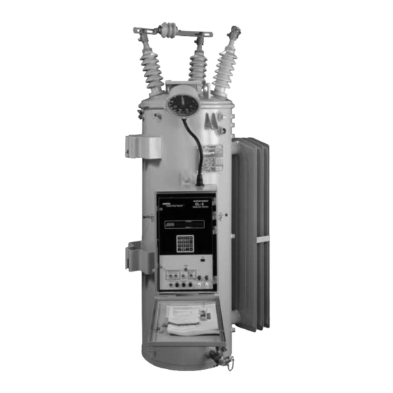
Figure 1.
VR-32 Voltage Regulator with CL-5 Series Control
Service Information
Advertisement
Table of Contents

Related Manuals for Cooper McGraw-Edison VR-32


Summary of Contents for Cooper McGraw-Edison VR-32
-
Page 1: Table Of Contents
When additional information is desired to satisfy a problem not covered sufficiently for the user’s purpose, please contact your Cooper Power Systems representative. October 2001 • Supersedes 12/00 • © 2001 Cooper Power Systems, Inc. - Page 2 McGraw-Edison VR-32 Regulator and CL-5 Series Control SAFETY FOR LIFE Cooper Power Systems products meet or exceed all applicable industry standards relating to product safety. We actively promote safe practices in the use and maintenance of our products through our service literature, instructional training programs, and the continuous efforts of all Cooper Power Systems employees involved in product design, manufacture, marketing, and service.
-
Page 3: S225-10-10
S225-10-10 MOV-TYPE SERIES CLAMP-TYPE CONNECTORS ARRESTER THREADED-STUD BUSHING TERMINALS BUSHINGS JUNCTION BOX INTERNAL ASSEMBLY LIFTING EYES HANDHOLE COVER COVER UPPER FILTER PRESS POSITION INDICATOR CONNECTION AUTOMATIC REGULATOR LIFTING LUGS PRESSURE RELIEF DEVICE SHUNT ARRESTER MOUNTING BOSSES CONTROL CABLE WITH (3 PER BUSHING) DISCONNECT PLUG BALL-TYPE OIL POLE MOUNTING... -
Page 4: Receiving, Installation And Maintenance
McGraw-Edison VR-32 Regulator and CL-5 Series Control Receiving, Installation and Maintenance Receiving CAUTION: Do not subject tap changer to Inspection temperatures above 150°F (66°C). To do so may cause damage to the contact panels, resulting in Prior to shipment, the regulator is thoroughly tested misalignment of the contacts. - Page 5 S225-10-10 WARNING: Connect the “S” bushing to the BYPASS SWITCH source, the “L” bushing to the load, and the “SL” bushing to neutral. To do otherwise may cause excessively high or low voltage on the load side of the regulator or cause severe damage to the regulator. DISCONNECTS Systems Connections A regulator can regulate a single-phase circuit, or...
- Page 6 McGraw-Edison VR-32 Regulator and CL-5 Series Control Mounting A regulator can be mounted on a pole, crossarm platform or elevating structure. Regulators are normally provided with either pole mounting brackets or a substation base according to the rating. An elevating...
- Page 7 If keypad or communication ports. not, proceed to Step 7, below. For quick set-up of Cooper Power Systems regulators, see Table 1-1, page 1-5. For complete set-up, see 5. Lift raise-lower switch to operate tap changer two or...
- Page 8 McGraw-Edison VR-32 Regulator and CL-5 Series Control TABLE 1-1 Setting the Controls for Basic Operation Security System Keys to Depress Display Description FUNCTION, 99, ENTER _ _ _ _ _ 12121, ENTER Func The security system is now activated for changing operational settings Set Voltage Range: 100.0 - 135.0 (Factory Setting: 120.0)
- Page 9 S225-10-10 TABLE 1-2 CL-5 Series Control Programming Checklist Function Factory Owner Next Step Activity/Question Check Code Step Power up control or run Self Test (FC 91). Pass = B; Fail = Refer to page 2-5 Access Security Level 3. 32123 Set Voltage Bandwidth Set the Forward Power Flow Control Settings --...
- Page 10 McGraw-Edison VR-32 Regulator and CL-5 Series Control TABLE 1-3 CL-5 Series Control Programming Checklist for Reverse Power Flow Detection and Operation Function Factory Owner Next Step Activity/Question Check Code Step Is voltage regulation required on the source and load side of regulator? No = BC;...
- Page 11 S225-10-10 Figure 1-7. Nameplate of a 60 hertz regulator with an internal series winding P.T.
- Page 12 McGraw-Edison VR-32 Regulator and CL-5 Series Control Cooper Power Systems Figure 1-8. Nameplate of a 50 hertz regulator indicating metric weights and volumes...
- Page 13 S225-10-10 Operational Check In-Service Operational Check With the control now set for basic operation, an Pre-Installation Operational Check operational check of manual and automatic operation should be performed as follows: The CL-5 Series Control has the facilities for either manual or automatic operation of the tap changer, using 1.
- Page 14 McGraw-Edison VR-32 Regulator and CL-5 Series Control a. The metering and operation is based upon the Removal From Service RMS value of the fundamental power line Determining Neutral Position frequency. Thus, the metered values exclude the influences of harmonic voltages which are probably present on the line.
- Page 15 S225-10-10 3. To increase safety, we recommend verifying Maintenance Program that the regulator is in the neutral position using Periodic Inspections the following three methods: Step-type voltage regulators are designed to provide a. Verify that the neutral indicator light on the many years of trouble-free operation.
- Page 16 McGraw-Edison VR-32 Regulator and CL-5 Series Control Removal of Control Front Panel WARNING: Do not pull open the current shorting switch, C, until the screws have been The front panel may be removed from the regulator with tightened on the interconnecting terminal block.
- Page 17 S225-10-10 Retanking the Regulator Retank the regulator as follows: 1. Be sure position indicator shows present position of the tap changer. If not, remove indicator cable in junction box from position indicator shaft after loosening set screw. Rotate indicator shaft until proper position is reached, then tighten set screw.
- Page 18 McGraw-Edison VR-32 Regulator and CL-5 Series Control Position Indicator & ADD-AMP b. If unit is out of oil more than four hours, it must be rebaked for a minimum of 24 hours Capability at 100°C (212°F). The maximum number of...
- Page 19 S225-10-10 configuration. The series winding on the input (source) BEZEL MAIN HAND side of the regulator (Figure 1-12) allows all windings COVER (control, shunt and series) to be located in one coil assembly. The load voltage is monitored by the control winding.
- Page 20 McGraw-Edison VR-32 Regulator and CL-5 Series Control TABLE 1-7 TABLE 1-8 ADD-AMP Capabilities of 60 Hz Ratings ADD-AMP Capabilities of 50 Hz Ratings †Load Current Ratings (amperes) †Load Current Ratings (amperes) Regulation Range (Wye and Open Delta) Regulation Range (Wye and Open Delta)
- Page 21 S225-10-10 REVERSING SOURCE CURRENT SWITCH BUSHING TRANSFORMER POLARITY MARKER LOAD BUSHING SERIES WINDING REACTOR EQUALIZER WINDING LOAD SOURCE JBB-C JBB-C SHUNT WINDING JBB-S SOURCE-LOAD JBB-G BUSHING CONTROL WINDING Figure 1-12. Power circuit — series winding located on the source-side (ANSI Type B) REVERSING SOURCE CURRENT...
- Page 22 McGraw-Edison VR-32 Regulator and CL-5 Series Control SOURCE LOAD BUSHING BUSHING CURRENT TRANSFORMER JBB-C JBB-C POLARITY SHUNT MARKER TRANSFORMER LOAD POTENTIAL LOAD TRANSFORMER SOURCE SERIES JBB-S TRANSFORMER JBB-G EQUALIZER WINDING REVERSING SWITCH REACTOR SOURCE-LOAD BUSHING Figure 1-14. Power circuit — series transformer...
- Page 23 S225-10-10 have a second voltage source installed internal to the TABLE 1-10 VR-32 Tap Connections and Voltage Levels (60 Hz) regulator to develop the source-side voltage supply. (For the CL-5C and subsequent controls, reverse power flow Nominal Test Overall may instead be handled using the source voltage Regulator Single Ratio Adjusting Data...
- Page 24 McGraw-Edison VR-32 Regulator and CL-5 Series Control Allowable System Voltages TABLE 1-11 VR-32 Tap Connections and Voltage Levels (50 Hz) Calculation of Overall P.T. Ratio Nominal Test Overall If the system voltage is other than those listed on the Regulator...
- Page 25 S225-10-10 Changing System Voltage additional safety measures, the V and V knife switches should also be opened.) For all regulators with quick disconnect, connector (Figure 1-9), an automatic solid- WARNING: Remove regulator from service state C.T. shorting device is located in the junction box. before performing internal lead connection This solid-state device automatically will short the C.T.
- Page 26 McGraw-Edison VR-32 Regulator and CL-5 Series Control Also included as a part of the motor circuit is an information in its decision making process, as described alternate feed to the motor called the holding switch under Control Operating Modes, page 2-8.
-
Page 27: Control Basics
S225-10-10 Control Basics Introduction TABLE 2-1 Control Specifications The CL-5 Series Control Physical Size ” H 10 ” W 2 ” D The McGraw-Edison CL-5 series control is a full-featured (44.5 cm 26.0 cm 6.35 cm) control which incorporates digital logic and micro- Weight lbs. - Page 28 McGraw-Edison VR-32 Regulator and CL-5 Series Control LCD DISPLAY KEYPAD DATA PORT NEUTRAL INDICATING LIGHT POWER SWITCH DRAG HAND (INTERNAL-OFF- RESET SWITCH EXTERNAL) VOLTMETER TERMINALS CONTROL SWITCH (AUTO/REMOTE-OFF- MANUAL) EXTERNAL POWER TERMINALS MANUAL RAISE/ LOWER SWITCH SUPERVISORY ON/OFF SWITCH MOTOR FUSE...
- Page 29 S225-10-10 Front Panel Components Voltmeter Terminals These allow the connection of a voltmeter so that the Lower Section - Grey potential sensed by the control (between the load (L) The lower section of the control contains components bushing and SL bushing of the regulator) can be which are similar to the other controls in the McGraw- measured.
- Page 30 McGraw-Edison VR-32 Regulator and CL-5 Series Control incremented, and the RAISE relay is de-energized, FUNCTION CODE FUNCTION-CODE VALUE thus opening its contacts. VALUE FIELD FIELD FIELD FIELD 8. As a result of the relay contacts opening, the motor HOUR, MINUTE...
- Page 31 There are three events which force the control into the operation is ensured by MERTOS4, an operating self-diagnostic routines: 1) The power is first turned system developed by Cooper Power Systems for on; 2) operator entry of the self-test mode (Function microprocessor-based systems. There are four error Code 91);...
- Page 32 McGraw-Edison VR-32 Regulator and CL-5 Series Control TABLE 2-2 Security Codes Security Level Accessible at Factory Programmed User Definable Functions Available at the Active Code Function Code Code Range No Code Required No Code Required No Code Required Read all parameters except security (Function Codes 96, 97, &...
- Page 33 S225-10-10 instance, the extensions of Function Code 18, are 3, 5, normally be set for 120.0 V unless it is desired to 7, 9, 11 and 13. When Function Code 18 is accessed the operate at a voltage level higher or lower than nominal. Total Harmonic Distortion (THD) is displayed.
- Page 34 McGraw-Edison VR-32 Regulator and CL-5 Series Control produces a current proportional to the load current, and Time Integrating resistive (R) and reactive (X) elements through which When the load voltage goes out-of-band, the time delay this current flows. As the load increases, the resulting circuit is activated.
- Page 35 S225-10-10 regulator is installed on any other system voltage, the Regulator Configuration, FC 41, correctly, the correct corresponding P.T. ratio must also be entered for proper relationship between the voltage and current is operation. This value includes the correction performed established.
-
Page 36: Control Function Codes
McGraw-Edison VR-32 Regulator and CL-5 Series Control Control Function Codes TABLE 3-1 CL-5 Series Regulator Control Function Codes Security Security Function Function Function Function Level Level Code Code Change/Reset Change/Reset FORWARD CONTROL SETTINGS Demand Time Interval, minutes Operation Counter (Q, R_, R... - Page 37 S225-10-10 Security Security Function Function Function Level Function Level Code Code Change/Reset Change/Reset 2 EEPROM Erase Failure METERING PROFILE RECORDER 3 Frequency Detection Failure Profile Period 4 No Sampling Interrupt-Failure (5, 10, 15, 30, 60, 90, 120 min.)** 5 Analog-To-Digital Converter-Failure 1 = Parameter 1, 2 = Parameter 2, 6 Invalid Critical Parameters-Failure 3 = Parameter 3, 4 = Parameter 4,...
- Page 38 McGraw-Edison VR-32 Regulator and CL-5 Series Control Key Entry Security Level Function Unit Limit Function Default Code Parameter Code Value Extension Measure Read Change Reset High Line Compensation, — –96.0 96.0 Resistance (Forward) • The resistive line drop compensation value is used to model the resistive line voltage drop between the regulator and the theoretical load center.
- Page 39 S225-10-10 Security Level Key Entry Function Unit Function Default Limit Code Parameter Code Value Extension Measure Read Change Reset High 12 (Cont.) — Percent Regulation • When the regulator output voltage is greater than the input voltage (regulator boosting), the sign is implied (+). When the output voltage is lower than the input voltage.
- Page 40 McGraw-Edison VR-32 Regulator and CL-5 Series Control Key Entry Security Level Function Unit Limit Function Default Code Parameter Code Value Extension Measure Read Change Reset High — Line Frequency • This is the frequency of the power line, as measured by the control.
- Page 41 S225-10-10 Key Entry Security Level Unit Function Default Limit Function Code Parameter Value Code Extension Measure Read Change Reset High Power Factor at Minimum “----” — kVA Demand (Forward) (invalid) • This is the instantaneous power factor of the load at the first time when the minimum kVA demand occurred, since last reset. •...
- Page 42 McGraw-Edison VR-32 Regulator and CL-5 Series Control Key Entry Security Level Function Unit Function Default Limit Parameter Code Code Value Extension Measure Read Change Reset High H, H_, H Source Voltage Demand (Forward) L, L_, ,L • This is the primary input voltage of the regulator, as a demand value, according to the demand time interval at Function Code 46.
- Page 43 S225-10-10 Key Entry Security Level Function Unit Function Limit Default Code Parameter Code Value Extension Measure Read Change Reset High H, H_, H kVA Load Demand (Reverse) Reset** L, L_, L • This is the load kVA during reverse power flow, as a demand value, according to the demand time interval at Function Code 46. •...
- Page 44 McGraw-Edison VR-32 Regulator and CL-5 Series Control Security Level Key Entry Function Unit Function Default Limit Parameter Code Code Value Extension Measure Read Change Reset High — Regulator Identification — 12345 32766 • Provision is made for entry of a number to uniquely identify each control.
- Page 45 S225-10-10 Security Level Key Entry Function Unit Function Default Limit Code Parameter Code Value Extension Measure Read Change Reset High — Current Calibration 100.0 400.0 • The current which the control actually measures, in milli-amps, is displayed at Function Code 48. •...
- Page 46 McGraw-Edison VR-32 Regulator and CL-5 Series Control Key Entry Security Level Function Unit Limit Function Default Code Parameter Code Value Extension Measure Read Change Reset High — Reverse Sensing Mode –– • The control offers six different response characteristics for reverse power flow operation, selectable by the user. The six modes,...
- Page 47 (Protocol 2179) (invalid) • Cooper Power Systems has developed advanced controls for various products utilizing common protocol communications. • Each control on the system can be uniquely addressed by the SCADA RTU or other communications device. • The control SCADA address is entered at Function 64 with a factory preset address of 5.
- Page 48 McGraw-Edison VR-32 Regulator and CL-5 Series Control Security Level Key Entry Function Unit Function Default Limit Code Parameter Code Value Extension Measure Read Change Reset High Communications Port “----” msec. Transmit Enable Delay - On (invalid) • When the control is set for transmit control handshaking (Function Code 66 = 2), the user may require a delay to occur between the time when the transmit enable is enabled to when data is transmitted.
- Page 49 S225-10-10 Security Level Key Entry Function Unit Default Limit Function Code Parameter Value Code Extension Measure Read Change Reset High Voltage Reduction Mode/ — — Tap to Neutral • The control has three voltage reduction modes available for user selection. The appropriate mode is activated by entering the corresponding code: 0 = Off 10 = Off, Tap to Neutral Enabled...
- Page 50 McGraw-Edison VR-32 Regulator and CL-5 Series Control Security Level Key Entry Function Unit Function Default Limit Code Parameter Code Value Extension Measure Read Change Reset High 1, 2 Soft Add-Amp Limits • The control has soft add-amp capabilities. 0 = Off, 1 = On (Default is off) •...
- Page 51 S225-10-10 Key Entry Security Level Function Unit Function Default Limit Parameter Code Code Value Extension Measure Read Change Reset High — Self Test — • The control will execute a self-diagnostic routine by entry of Function Code 91. • This causes the system to re-boot, or initialize itself, and in so doing to check the various components for failures. •...
- Page 52 McGraw-Edison VR-32 Regulator and CL-5 Series Control Security Level Key Entry Function Unit Limit Function Default Code Parameter Code Value Extension Measure Read Change Reset High — Level 2 Security Code — 12121 10000 19999 • The number to be used as the level 2 security code is entered here.
-
Page 53: Control Advanced Features
S225-10-10 Control Advanced Features Differential Voltage Instantaneous Metering Unless specifically ordered, or required as a part of the Instantaneous metering values are stored in RAM, and specified operation, most regulator designs will be are refreshed once per second. They may be read at without the internal source-load differential P.T. - Page 54 McGraw-Edison VR-32 Regulator and CL-5 Series Control The task works like this: • 13 - Power Factor • 14 - kVA Load 1. For 3 minutes after a power outage or power • 15 - kW Load reversal, no demands are calculated. This allows •...
- Page 55 S225-10-10 that is, all values for all four parameters will be set to 0. prior value of FC 12 was “–16” the prior value will be To reset all profiler values to 0 either turn the power off, maintained. These conditions could occur if the present or change one of the Function Code 85 extension tap position was manually set incorrectly.
- Page 56 McGraw-Edison VR-32 Regulator and CL-5 Series Control marked V The software of the control then recognizes Forward Source this differential/source voltage as a source voltage, and Load Voltage Reverse Current Supply will function accordingly. Load Current Load Voltage The CL-5C and later generation controls have the ability...
- Page 57 S225-10-10 METERING: Always operates in the reverse direction, regardless of power flow direction. If forward power NORMAL FORWARD occurs, the metering functions remain on the source METERING (S bushing) side of the regulator — no forward demand "REV PWR" OFF readings will occur.
- Page 58 McGraw-Edison VR-32 Regulator and CL-5 Series Control forward until the current exceeds the 1% threshold in the Neutral Idle Mode reverse direction. At this time the various parameters Function Code 56 = 4. Source voltage is required. use the reverse settings, and the REV PWR annunciator turns on.
- Page 59 S225-10-10 Co-generation Mode used when the current exceeds the fixed 1% forward metering threshold. The demand values acquired during Function Code 56 = 5. Source voltage is required. reverse power flow are stored as reverse metered data but the values are not scaled (to reflect the other side of In recent years, there have been a growing number of the regulator) since the operating direction of the voltage regulator applications involving co-generation by...
- Page 60 McGraw-Edison VR-32 Regulator and CL-5 Series Control OPERATION: (Figure 4-12.) The control determines connected SCADA system. The purpose of the voltage which settings (forward/reverse) to use by sensing the limiter is to protect the consumer from abnormally high real and reactive components of the current. The control...
- Page 61 S225-10-10 Remote (Latching) and Pulse Mode 127 V HIGH-VOLTAGE LIMIT (F.C. 81) 125 V EDGE OF HIGH GREY ZONE The remote latching and pulse mode of voltage NORMAL reduction will be discussed in Analog SCADA. RANGE OF OPERATION Supervisory Control and Data 120 V VOLTAGE SETTING (F.C.
- Page 62 McGraw-Edison VR-32 Regulator and CL-5 Series Control Function Codes 73, 74 and 75 respectively. As shown in FACTORY-INSTALLED Table 4-3, latching contact 1 activates the VR JUMPER programmed at Function Code 73, latching contact 2 activates the VR programmed at Function Code 74, and latching both contacts activates the VR programmed at Function Code 75.
- Page 63 S225-10-10 USER-PROVIDED REMOTE VOLTAGE REDUCTION MODULE TB 1 REMOVE JUMPER FOR AUTO INHIBIT TB 3 CR 1 TB 8 CR 2 1 2 3 4 5 6 7 AUTO HS 2 INHIBIT HS 1 RELAY RAISE LOWER 4 3 2 1 V 9 V 7 V S V M C 1 C 3 HS R 3 L 3 NL DHR TB 2...
- Page 64 McGraw-Edison VR-32 Regulator and CL-5 Series Control Active Control Security Level Local Operator Security Through the communications channel, the SCADA If the local operator changes the control active security master may read the CL-5 Series data points, write to level to level 1 or above, or security override is set to certain data points, or reset certain data points.
-
Page 65: Tap Changer
S225-10-10 Tap Changer Tap Changer Operation Spring- and Direct-drive Tap Changers Regulators for low-current applications use stored energy spring-drive tap changers, most commonly on ratings 219 A and below. The tap changer for a specific rating is shown on the rating plate. Figures 5-1 (95 kV BIL and below) and 5-2 (150 kV BIL) illustrate typical spring-drive mechanisms. - Page 66 McGraw-Edison ® VR-32 Regulator and CL-5C Control segment, the spring-drive mechanism will be loaded and the segment is locked to prevent any further motion in that direction. The reversing switch motion on the direct-drive tap changers occurs as the main movable contact goes from neutral to the first raise position.
- Page 67 S225-10-10 2. The reversing stationary contacts are connected to opposite ends of the series winding. The reversing movable contacts connect the neutral stationary contacts and load bushing to the reversing stationary contact. NOTE: The neutral stationary contact in the direct- drive tap changer has both arcing and non-arcing contact conditions.
- Page 68 McGraw-Edison ® VR-32 Regulator and CL-5C Control 8. Pin drops into the hole in the actuator 180° from 7. Neutral light switch opens. the start position. 8. Geneva pinion completes second revolution and 9. At this point, the crank arm is at top dead-center continues to rotate.
- Page 69 S225-10-10 11. The brake engages a disk in the main sprocket and brings it to a stop at mid travel. 12. The motor shaft has completed a 360 degree turn. The elapsed time from step 1 to step 13 is 250 milliseconds.
-
Page 70: Troubleshooting Guide
Cooper Power Systems McGraw-Edison ® VR-32 Regulator and CL-5 Series Control Service Information Troubleshooting Guide Complete Regulator in Service 2. Toggle the raise switch and measure the voltage between terminals R and G on terminal board . The voltage reading should be approximately WARNING: When troubleshooting energized the set voltage setting. - Page 71 S225-10-10 Function Code 56, Reverse Sensing Mode. Set it the control power supply. If these checks are correct, to 0, if it is not there already. Retry the automatic then the malfunction is probably in the control. Refer to mode of operation. Control Troubleshooting, following.
- Page 72 0, 6, 7 or 10 is displayed, the control has failed, 11. Measure the voltage between terminals L and G and in need of repair. Contact Cooper Power on terminal board. The voltage reading should be Systems for return authorization information. If 10 is approximately 120 V ac.
- Page 73 PI is in neutral via the neutral light of the control and housing). Note that the new Cooper PI has a visual inspection of the tap changer. If the position one-piece input shaft/coupling and a raised mark indicator does not also show neutral, refer to at the 12 o'clock position on the PI housing hub.
- Page 74 McGraw-Edison ® VR-32 Regulator and CL-5 Series Control performed for both the voltage and current circuits with 4. Adjust the voltage source to provide 120.0 V to the the following steps: control, as read on the reference voltmeter. 5. Before calibration can be performed, security WARNING: It must be verified that both the level 3 must be activated.
- Page 75 S225-10-10 Current Calibration by entering the proper security code at Function Code 99. Depress the following keys on the 1. Connect an accurate true-RMS-responding keypad: ammeter in series with the current source. FUNCTION, 99, ENTER; 32123, ENTER 2. Connect a stable 60/50 Hz current source (with The proper level is now activated.
- Page 76 McGraw-Edison ® VR-32 Regulator and CL-5 Series Control CURRENT TRANSFORMER CIRCUIT BOARD CONNECTORS (TOROIDAL COIL) CONNECTOR P4 11 ORANGE LOAD SOURCE BUSHING 10 VIOLET BUSHING 9 WHITE 8 BROWN SERIES JBB-C JBB-C 7 YELLOW WINDING 6 WHITE/PURPLE REMOVABLE GROUND 5 (BLANK) Located on back 4 WHITE/RED panel plate inside...
- Page 77 S225-10-10 COUPLER CL5 CIRCUIT BOARD REMOTE VOLTAGE REDUCTION NEUTRAL SUPERVISORY AUTO COUPLER LAMP ENABLE SWITCH SENSE COUPLER COUPLER COUPLER MOTOR RELAYS CURRENT SENSE COUPLER LOWER SOURCE RAISE DIFF MOVABLE SOLDERED JUMPER AUTO RAISE SUPERVISORY MANUAL LOWER DRAG HAND REMOVABLE RESET JUMPER FOR BLOCKING RELAY...
- Page 78 McGraw-Edison ® VR-32 Regulator and CL-5 Series Control JUNCTION BOX TERMINAL BOARD (JBB) TCB-E 3 CURRENT TCB-E 2 JBB-C 1 TRANSFORMER (C) TO CONTROL TCB-E 1 JBB-C 2 TERMINAL BOARD AND POSITION INDICATOR TCB-G S 1 E 1 E 2 F 1 TAP CHANGER TERMINAL BOARD (TCB) CONTROL WINDING...
- Page 79 S225-10-10 JUNCTION BOX TERMINAL BOARD (JBB) TCB-E 3 CURRENT TCB-E 2 JBB-C 1 TRANSFORMER (C) TO CONTROL TCB-E 1 JBB-C 2 TERMINAL BOARD AND POSITION INDICATOR JBB-S 4 S 1 E 1 E 2 E 3 TAP CHANGER TERMINAL BOARD (TCB) TRANSFORMER CONTROL WINDING NL-NC...
- Page 80 McGraw-Edison ® VR-32 Regulator and CL-5 Series Control TO POSITION INDICATOR JBB-G — WHITE AND REGULATOR TANK JBB-HS — ORANGE RLS-1 — BLUE LLS-1 — GRN/BLK REMOVABLE JUMPERS REMOVABLE JUMPERS JBB-NL — RED/BLK FOR ACCESSORIES REMOVABLE FOR ACCESSORIES JBB-DHR — ORG/BLK GROUND JBB-S —...
-
Page 81: Accessories
Its Graphic User Interface is easy to use and Cooper Control Interface Software understand. Online help and a complete User Manual The Cooper Control Interface (CCI) is a Windows-based make the program easy to learn and generous configuration software package for use with the regulator toolbars make working within the program efficient. - Page 82 McGraw-Edison ® VR-32 Regulator and CL-5 Series Control new file format. This conversion facilitates the transition from the old DOS-based applications to the new applications. PC to Data Port Cable For direct connection of a PC to the Data Port of the CL-4 or CL-5 (and also the Form 4C recloser control) a special cable is required.
- Page 83 S225-10-10 The boards are self-powered from the internal regulator fan on or off when the top-oil temperature reaches potential transformer. A connection from the interface predetermined temperature limits. The thermal switch board is made to a port located on the inside of the CL-5 has an upper limit adjustable from 80°C to 110°C.
-
Page 84: Spare Parts
EPIC CD-ROM that requires only a catalog SPRING or serial number. This CD-ROM covers parts for VR-32 and Auto-booster regulators built since 1981. Consult WASHER your Cooper Power Systems sales representative for CONICAL SPRING WASHER information on receiving a CD. ROD ASSEMBLY HEX JAM NUT Figure 8-1. - Page 85 S225-10-10 REVERSING NEUTRAL STATIONARY CONTACT ASSEMBLY SHIELD REVERSING STATIONARY CONTACT MAIN MOVABLE CONTACT Figure 8-3. Replacement parts for direct drive tap changer 770B STATIONARY ARCING CONTACT ASSEMBLY REVERSING NEUTRAL STATIONARY CONTACT ASSEMBLY MOTOR KIT FOR BOTH 770B AND 660C REVERSING MOVABLE CONTACT REVERSING...
- Page 86 McGraw-Edison ® VR-32 Regulator and CL-5 Series Control QUIK-DRIVE HOLDING SWITCH ASSEMBLY CHAIN MOTOR CAPACITOR 50 uF 440 VOLTS 100°C RIGHT HAND REVERSING STATIONARY MAIN STATIONARY CONTACT CONTACT LEFT HAND REVERSING MAIN STATIONARY CONTACT REVERSING STATIONARY BRAKE ASSEMBLY MOTOR RIGHT HAND MAIN MOVABLE CONTACT LEFT HAND MAIN MOVABLE CONTACT...
-
Page 87: Index
S225-10-10 Index Section-Page Number Section-Page Number Accessing ..............1-4, 2-6 Demand Time Interval ............3-9 ADD-AMP Feature ............1-15 Diagnostics..............2-5, 3-16 Hard ................4-10 Differential P.T..............4-1 Soft................3-15 Digital Communications ........4-11 to 4-12, 7-2 Address, Communications ..........3-12 Elevating Structure .............1-3 ANSI Type A..............1-18 Error Codes ..............2-5, 9-2 ANSI Type B..............1-18 External Features, VR-32 ............2 Arresters... - Page 88 McGraw-Edison ® VR-32 Regulator and CL-5 Series Control Section-Page Number Section-Page Number Reversing ..............5-1 Characteristics ............1-12 Supervisory ............2-3, 4-12 Maintenance ..............1-1 System Connections ............1-2 One-touch Method..............2-6 System Line Voltage ..........1-21, 2-8, 3-9 Operation System Protection ............2-4 to 2-5 Automatic ..............2-4 System Status Codes ............3-16 Manual ................2-4 Tap Changer ............5-1 to 5-5...
- Page 89 S225-10-10 S225-10-10 TABLE 9-3 CL-5 Series Regulator Control Function Codes Security Security Function Function Level Level Function Function Code Code Change/Reset Change/Reset FORWARD CONTROL SETTINGS Demand Time Interval, minutes Operation Counter (Q, R_, R , 1, 2, 3, 4, 5, 6)* 3* Tap Changer Selection Set Voltage 0 = Quik Drive, 1 = Spring/Direct Drive...
- Page 90 McGraw-Edison McGraw-Edison ® ® VR-32 Regulator and CL-5 Series Control VR-32 Regulator and CL-5 Series Control TABLE 9-3, Continued CL-5 Series Regulator Control Function Codes Security Security Function Function Level Level Function Function Code Code Change/Reset Change/Reset 2 EEPROM Erase Failure METERING PROFILE RECORDER 3 Frequency Detection Failure Profile Period...
- Page 91 (262) 547-1251 For service-related inquiries, e-mail us at: tpservicegroup@cooperpower.com ©2001 Cooper Industries, Inc. P.O. Box 1640 Waukesha, WI 53187 ADD-AMP ™ is a registered trademark of Cooper Industries, Inc. McGraw-Edison ® is a trademark of Cooper Industries, Inc. http://www.cooperpower.com ø...
Need help?
Do you have a question about the McGraw-Edison VR-32 and is the answer not in the manual?
Questions and answers