Table of Contents
Advertisement
Quick Links
Reclosers
Types VW, VWV27 and VWV38
Maintenance Instructions
14.4 Kv • 560 Amp (Type VW) (Serial No. 510 and
after or beginning with CP57.)
24.9 Kv • 560 Amp (Type VWV27) (Serial No. 144
and after or beginning with CP57.)
34.5 Kv • 560 Amp (Type VWV38) (Serial No. 101
and after or beginning with CP57.)
Before performing electrical tests on types VW and VWV
Reclosers, refer to Service Information S280-90-1.
CAUTION
Do not energize this equipment out of oil.
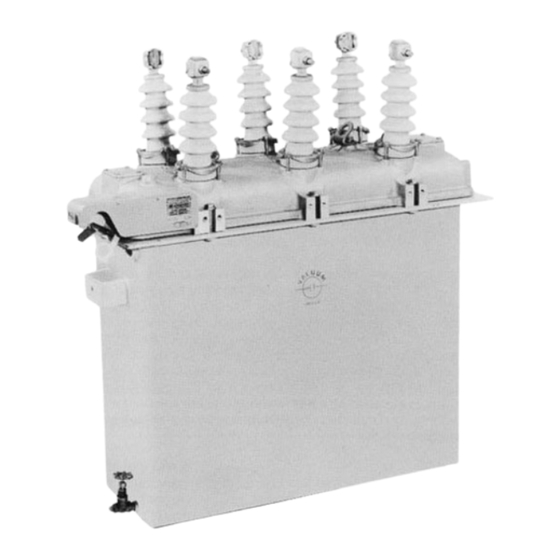
Figure 1.
Type VW vacumm-interrupting, hydraulicaly controlled, automatic circuit recloser.
CONTENTS
Safety for Life ......................................................................2
Introduction .........................................................................2
Description and Operation ..............................................2
General ..............................................................................2
Manual Operating Handle ...............................................2
Non-Reclosing Lever .......................................................2
Contact Position Indicator ................................................2
Vacuum Interrupters ........................................................3
Closing Solenoid ..............................................................3
Closing Solenoid Contactor .............................................3
Hydraulic Pump and Lockout Piston ..............................3
Series Trip Solenoids .......................................................3
Time Delay Unit ................................................................3
Mechanism Operation ......................................................4
Hydraulic Control System Operation ............................4
Maintenance ........................................................................5
Frequency of Maintenance .............................................5
Periodic Maintenance Inspection ....................................5
Manual Operation of the Recloser ..................................6
Mechanism In Oil ...........................................................6
Mechanism Out of Oil ...................................................7
Insulation Level Withstand Tests ....................................7
Oil Condition ......................................................................8
These instructions do not claim to cover all details or variations in the equipment, procedure, or process described, nor to provide direction for meet-
ing every possible contingency during installation, operation, or maintenance. When additional information is desired to satisfy a problem not covered
sufficiently
for
the
December 1986 • New Issue
RADIATION
WARNING
user's
purpose,
please
Shop Maintenance Procedures .................................9
Control Lever Overtravel Adjustments ......................9
Bushings ...................................................................9
Type VW Bushings ................................................9
Type VWV27 and VWV38 Bushings ....................10
Vacuum Interrupters ................................................12
Closing Solenoid Contactor .....................................12
Closing Solenoid ......................................................12
Series Trip Solenoid ..................................................13
Solenoid Disassembly .............................................13
Solenoid Replacement ............................................13
Time Delay Unit ..........................................................13
Maintenance .............................................................13
Replacement ............................................................14
Removing Mechanism from Head ...........................14
Reinstalling Mechanism into Head ..........................14
Testing .........................................................................14
Notes............................................................................15
Service Parts List .......................................................15
Bushing Part (Figure 25) ..........................................17
Head and Tank Assembly (Figure 26) .....................19
(Figure 28) ...............................................................23
contact
your
Cooper
Service Information
S280-30-7
Power
Systems
sales
99001KM
engineer.
1
Advertisement
Table of Contents

Related Manuals for Cooper VW


Summary of Contents for Cooper VW
-
Page 1: Table Of Contents
Types VW, VWV27 and VWV38 S280-30-7 Maintenance Instructions 14.4 Kv • 560 Amp (Type VW) (Serial No. 510 and after or beginning with CP57.) 24.9 Kv • 560 Amp (Type VWV27) (Serial No. 144 and after or beginning with CP57.) 34.5 Kv •... -
Page 2: Safety For Life
FOR LIFE FOR LIFE Cooper Power Systems products meet or exceed all applicable industry standards relating to product safety. We actively promote safe practices in the use and maintenance of our products through our service literature, instructional training programs, and the continuous efforts of all Cooper Power Systems employees involved in product design, manufacture, marketing, and service. -
Page 3: Introduction
A service parts list, The location of the major components of a VW recloser are keyed to exploded-view drawings of the recloser is included at shown in Figure 2. They are similar for the VWV27 and VWV38 the back of the manual. -
Page 4: Vacuum Interrupters
Types VW and VWV Maintenance Instructions Vacuum Interrupters When the recloser mechanism is sequenced to the delayed Circuit opening and fault interruption is achieved within the three operation phase, the speed of plunger movement is restrained sealed vacuum interrupters. The moving contact rod assemblies by a time-delay unit. -
Page 5: Mechanism Operation
S280-30-7 MECHANISM OPERATION The operating mechanism, mounted in the head, opens and closes the vacuum interrupter contacts. Contact opening is initi- ated by a series trip solenoid which triggers the trip mechanism QUICK RESET to release the loaded opening springs. Contact closing is per- formed by the closing solenoid which also charges the opening springs and resets the mechanism for the next trip operation. -
Page 6: Maintenance
(at a rate of approximately 90 seconds per operation at 25° C) to reset the recloser mechanism. • When Type VW, VWV27 and VWV38 reclosers are operated under usual service conditions as defined in ANSI (American National Standards Institute) C37.60, “Standard Requirements for Automatic Circuit Reclosers for Alternating Current Systems,”... -
Page 7: Manual Operation Of The Recloser
S280-30-7 15. Reinstall bushings, use new gaskets. (See page 8 for instal- CAUTION lation procedures.) Be sure the recloser is open (yellow operating handle under 16. Drain the tank, and clean out all sludge and carbon deposits. the sleet hood is down) before untanking, so that the mecha- If oil is to be reused it must be filtered and the dielectric nism can not be accidently tripped while out of oil. -
Page 8: Mechanism Out Of Oil
Testing is performed at 75% of the rated low fre- The mechanism may be damaged if it is "quick-tripped" with quency withstand voltage (37.5 kv for the VW, 45 kv for the the yellow operating handle while out of oil. -
Page 9: Oil Condition
If the control lever is not adjusted properly, remove the C-ring and slide the control lever from the shaft. Rotate the control lever Figure 13. Replacing bushing w/tanked Type VW recloser. 1. Unscrew bushing terminal and discard terminal gasket. 2. Remove three hex head capscrews and clamps that secure the bushing to head and lift out porcelain. -
Page 10: Type Vwv27 And Vwv38 Bushings
Types VW and VWV Maintenance Instructions 5. Using a new gasket, install new porcelain over bushing rod 6. Twist off the split aluminum clamping ring from old bushing and install on new bushing, if it is in good condition; replace and into the head. -
Page 11: Vacuum Interrupters
S280-30-7 5. Install new bushing through head. action can be verified by observing the scribe mark on the 6. Position bushing with stud end of terminal pointing outward. contact rod. It will move downward to just above (or below) 7. Position clamping ring with split centered between the two out- the fiber disk at the top of the interrupter. -
Page 12: Closing Solenoid Contactor
Types VW and VWV Maintenance Instructions 15. Manually trip and close the recloser several times to check Closing Solenoid interrupter operation. The closing solenoid coil is connected phase-to-phase and is rated to operate at full system voltage. It is protected with two NOTE: Contact movement can be verified by observing the move- fuses, one on either side. -
Page 13: Series Trip Solenoid
S280-30-7 SERIES TRIP SOLENOID The continuous current rating and the trip current rating of the recloser can be changed by installing new coils in the series trip solenoids. Tripping occurs at about 200% of the continuous cur- rent rating of the standard coil and at about 140% when the alter- nate (400X or 560X) coils are used. -
Page 14: Replacement
NOTE: By temporarily substituting eye-bolts for two of the hex head TESTING bolts in the bottom of the closing solenoid frame, the mechanism can Procedures for testing the Type VW, VWV27 and VWV38 be easily lifted and handled with a hoist. reclosers are included in the Installation Manual S280-30-1. -
Page 15: Notes
S280-30-7 NOTES... -
Page 16: Service Parts List
To assure correct receipt of any parts order, always include ual. Further breakdown of listed assemblies is not recom- recloser type and serial number. Because of Cooper Power Sys- mended. tem's continuous improvement policy, there may be instances... - Page 17 Ouan. Item Catalog Quan. Description Number Req’d. Description Number Req’d. Bushing assembly—Type VW Bushing ceramic—Type VW consists of items 10 thru 13) Standard creepage KP1110R 13” standard creepage KA717R25 Standard creepage with BCT 13” standard creepage with accy. KP171 W BCT accy.
- Page 18 Types VW and VWV Maintenance Instructions Figure 26. Head and tank assemblies.
- Page 19 Shaft and lever assembly KA319R KP3190A11 shaft bushings KA840R Spacer KP3007A8 Head gasket KP2103A8 Nameplate Flatwasher, #14S brass K900525026056A Type VW KRW107F1 Cotter pin,3/32 x 1/2, stl K970801093050A Type VWV27 KRW127F1 Roll pin,3/32 x 1/2, stl K970801093050C Type VWV38 KRW173F Counter KA28COA2 Self-tapping screw, Type F.
-
Page 20: Trip Coil And Interrupter Mechanisms (Figure 27)
Types VW and VWV Maintenance Instructions Figure 27. Trip coil and interrupter mechanisms. - Page 21 Series coil replacement kit 1/4-20 x 1, stl KP2036A10 (includes item 20, Figure 26) Vacuum interrupter (Add coil rating as suffix Type VW S/N 3104 and before to catalog number) Phase A & B KRW705VA Phases A and B KA835W2-...
- Page 22 Types VW and VWV Maintenance Instructions Figure 28. Closing solenoid and hydraulic control parts.
- Page 23 57 (Figure 27), and Operating lever coupler KP2447R voltage data plate, 19 Pivot pin KP418H Figure 26). Retaining ring, Type C, 1/4, Type VW and VWV27 reclosers K970901250000M below 20 kv Lockout piston link KP122R 2.4 kv KA834R1 KP3055A3 3.3 kv...
- Page 24 Types VW and VWV Maintenance Instructions 1045 Hickory Street © 2005 Cooper Power Systems or its affiliates. Pewaukee, WI 53072 ® Kyle is a registered trademark of Cooper Power Systems or its affiliates. www.cooperpower.com 7/05...
Need help?
Do you have a question about the VW and is the answer not in the manual?
Questions and answers