Table of Contents
Advertisement
Quick Links
Reclosers
Type L Recloser
Maintenance Instructions
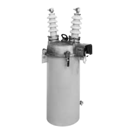
Figure 1.
Type L single-phase, hydraulically controlled circuit recloser.
Contents
Safety Information . . . . . . . . . . . . . . . . . . . . . . . . . 2
. . . . . . . . . . . . . . . . . . . . . . . 3
Acceptance and Initial Inspection . . . . . . . . . . . . 3
Handling and Storage . . . . . . . . . . . . . . . . . . . . . 3
Introduction . . . . . . . . . . . . . . . . . . . . . . . . . . . . . . 3
Non-Reclosing Feature . . . . . . . . . . . . . . . . . . . . 4
Manual Operating Lever . . . . . . . . . . . . . . . . . . . 4
Untanked view of recloser . . . . . . . . . . . . . . . . . . 5
Maintenance . . . . . . . . . . . . . . . . . . . . . . . . . . . . . . 6
Specifications and Ratings . . . . . . . . . . . . . . . . . 6
General Maintenance . . . . . . . . . . . . . . . . . . . . . 6
Periodic Inspection and Maintenance . . . . . . . . . 6
Shop Maintenance . . . . . . . . . . . . . . . . . . . . . . . 6
Series Trip Solenoid Disassembly . . . . . . . . . . . .11
Series Trip Solenoid Assembly . . . . . . . . . . . . . .12
Hydraulic Mechanism . . . . . . . . . . . . . . . . . . . . .14
Current Curves . . . . . . . . . . . . . . . . . . . . . . . . . . . .20
97000 to 208749 . . . . . . . . . . . . . . . . . . . . . . . . .20
May 2001 • Supersedes 9/82
Printed in USA
S280-15-1
208750 and Above . . . . . . . . . . . . . . . . . . . . . . .21
Adjustment . . . . . . . . . . . . . . . . . . . . . . . . . . . . .23
208750 and above . . . . . . . . . . . . . . . . . . . . . . . . . .24
Pump Piston . . . . . . . . . . . . . . . . . . . . . . . . . . . .24
Trip Linkage . . . . . . . . . . . . . . . . . . . . . . . . . . . .25
Testing . . . . . . . . . . . . . . . . . . . . . . . . . . . . . . . . . .26
Pump Piston . . . . . . . . . . . . . . . . . . . . . . . . . . . .26
Trip Point . . . . . . . . . . . . . . . . . . . . . . . . . . . . . .26
Insulation Withstand Tests . . . . . . . . . . . . . . . . . .27
Test Results . . . . . . . . . . . . . . . . . . . . . . . . . . . .27
Contact Operation Test . . . . . . . . . . . . . . . . . . .27
Bushings, Head, and Tank Assemblies . . . . . . . . .27
Bushings . . . . . . . . . . . . . . . . . . . . . . . . . . . . . . .27
Head Mechanism . . . . . . . . . . . . . . . . . . . . . . . .28
Tank Assembly . . . . . . . . . . . . . . . . . . . . . . . . . .35
Service Information
010059KM
1
1
Advertisement
Table of Contents

Subscribe to Our Youtube Channel
Related Manuals for Cooper S280-15-1


Summary of Contents for Cooper S280-15-1
-
Page 1: Table Of Contents
Reclosers Service Information Type L Recloser S280-15-1 Maintenance Instructions 010059KM Figure 1. Type L single-phase, hydraulically controlled circuit recloser. Contents Safety Information ......2 Curve Adjustment, Serial Numbers 208750 and Above . -
Page 2: Safety Information
FOR LIFE FOR LIFE Cooper Power Systems products meet or exceed all applicable industry standards relating to product safety. We actively promote safe practices in the use and maintenance of our products through our service literature, instructional training programs, and the continuous efforts of all Cooper Power Systems employees involved in product design, manufacture, marketing, and service. -
Page 3: Product Information
Quality Standards includes instructions for its periodic inspection, testing and shop repairs. Also are included are service-parts The Quality System at the Cooper Power Systems, Kyle lists, keyed to exploded-view drawings, and ordering Distribution Switchgear plant is certified to the following instructions. -
Page 4: Non-Reclosing Feature
Non-Reclosing Feature rating, which is selected to meet circuit requirements. The non-reclosing feature, standard on all Cooper Power When the recloser senses a fault current, it automatically Systems reclosers, is set with a hookstick-operated opens, and if the fault is temporary, it automatically lever. -
Page 5: Untanked View Of Recloser
S280-15-1 SAFETY FOR LIFE UNIVERSAL CLAMP-TYPE SLEET HOOD TERMINALS Houses manual operating Accept copper or aluminum lever, non-reclosing lever, conductors horizontally or and operations counter. vertically. NAMEPLATES COVER-CLAMPED Show complete recloser BUSHINGS data. Field Replaceable. OPERATIONS COUNTER LIFTING STRAP Records all recloser trip Facilitates lifting during operations (not visible). -
Page 6: Maintenance
22 kV or lower, 1,500 1,500 1,500 should be replaced. Use only oil that meets the require- 2,100 2,100 2,100 ments for Cooper Power Systems switchgear. Refer to Cooper Power Systems Reference Data R280-90-1. 3,000 3,000 3,000 4,200 4,200 4,200 Used oil must be treated before reusing. - Page 7 S280-15-1 SAFETY FOR LIFE 3. Remove mechanism from tank. Loosen four bolts that 7. Inspect stationary contacts. secure the tank to the head casting, and loosen the If replacement of the exhaust structure or moving con- gasket seal between tank and head casting. The tacts is indicated, inspect stationary contacts.
-
Page 8: Shop Maintenance
Type L Recloser Maintenance Instructions 14. Test mechanical operation. 15. Direct-current testing: To prove the recloser is in good operating condition, perform direct-current An easy, effective test can be performed as follows: testing as follows: A. Move the operating lever to the CLOSED position A. - Page 9 S280-15-1 SAFETY FOR LIFE Moving Roll Guide Contact Tube Yoke Contact 83420KM-A Exhaust Generator Tube Tube Figure 12. Removing Guide Tube. (Serial number 134024 and above). Cross-Blast Tube Wedges Figure 10. 82159KM-A Removing contact yoke. Wedges 83418KM-A Figure 13. Removing contact-tube wedges.
- Page 10 Type L Recloser Maintenance Instructions 5. Figures 15 and 16 show cross-sectional views of sta- Note: It is recommended that complete stationary con- tact tube assemblies be installed if any of the sta- tionary contact tube assemblies. To dismantle either tionary contact components are found defective.
-
Page 11: Series Trip Solenoid Disassembly
S280-15-1 SAFETY FOR LIFE Series-Trip Solenoid coil Bridge Plate Observe the following procedure for disassembly of a series-trip solenoid: 1. If the arc-interrupting assembly has not been Bronze Palnut Coil Leads removed previously, observe procedures outlined in the Arc-lnterrupting Assembly section. -
Page 12: Series Trip Solenoid Assembly
Type L Recloser Maintenance Instructions Bridge Cushion Solenoid Plate Washer Frame Shoe Cap Screw Lockwasher Figure 20. 82156KM-A Bridge plate removal. Bypass Using a 3/4-in. box wrench, remove four hexnuts that secure the solenoid bridge plate. Lift this plate off as shown in Figure 20. Note that a red cushion Figure 21. - Page 13 S280-15-1 SAFETY FOR LIFE 010058KM Figure 22. Coil assembly for units below serial number 42775. 010026KM 82006KM-1 Figure 23. Coil assembly for units with serial number 42775 and above. See Table 7 for parts identification.
-
Page 14: Hydraulic Mechanism
Type L Recloser Maintenance Instructions Hydraulic Mechanism TABLE 7 Series Trip Solenoid Assembly (Figures 19a and 19b) This mechanism should require no maintenance, but components may be changed to provide different opera- tion sequences. Furthermore, removal of this mechanism Item Catalog may be required to gain access to the head operating Description... - Page 15 S280-15-1 SAFETY FOR LIFE 3. With a 1/2-in. wrench, remove the cap screw that 2. Insert the trip piston in its cylinder. Pull the spring out secures the operation selector plate, orifice plate, as shown in Figure 28 and insert a thin plate to hold and gasket.
- Page 16 Type L Recloser Maintenance Instructions Figure 28. 82154KM-A Removing check valve seat. 82160KM-A Figure 29. Slide valve, check valve and trip valve removed. Figure 30. 010003KM Removing stringers and pump piston.
- Page 17 S280-15-1 SAFETY FOR LIFE 82153KM-A Figure 31. Removing trip-piston spring.
- Page 18 Type L Recloser Maintenance Instructions 82166KM-A Figure 32. Parts for hydraulic mechanism on units below serial number 208750 See Table 8 for parts identification.
- Page 19 S280-15-1 SAFETY FOR LIFE TABLE 8 Parts list for hydraulic mechanism below 208750 (Shown in Figure 32.) Item Catalog Description KA69L1 Solenoid frame assembly KP12L1 Frame shoe KP155H Ball check valve seat and 1/4-in.-steel ball KP3051 A1 KA725H Pump piston assembly KP3055A1 Pin--1/4 in.
-
Page 20: Adjusting Sequences And Time Current Curves
Type L Recloser Maintenance Instructions ADJUSTING SEQUENCES AND TIME CURRENT CURVES Curve Adjustment Sequence Adjustments Serial Numbers 97000 to After any change or servicing of the hydraulic mecha- 208749 nism, make sure to remove any air that may have been entrapped, by operating the yellow control handle manu- Hydraulic parts as listed in Tables 9, 10, and 11 permit ally seven or eight times. -
Page 21: Curve Adjustment Serial Numbers 208750 And Above
S280-15-1 SAFETY FOR LIFE Curve Adjustment Serial Numbers 208750 and Above Type L reclosers, with serial numbers 208750 and above, TABLE 9 Type L-- Sequence Selector Options offer several sequence options, and adjustment depends on which option originally was ordered. - Page 22 Type L Recloser Maintenance Instructions TABLE 10 Sequence selector parts identification Item Part Number Description Option 1 Option 2 Option 3 L-387A Trip Rod L-388A Trip Rod Guide, 2-1/16" Long L-389A Trip Adjuster L-390A Adapter, 1-3/4" Long L-391A Trip Adjuster Stop (spacer) L23A-1 Trip Piston Assembly –...
-
Page 23: Control Valve For Time Current Curve Adjustment
S280-15-1 SAFETY FOR LIFE TABLE 12 Sequence Selection Desired Option Solenoid Slide Valve Slide (See Table 9) Frame Used Stops Sequence Valve 3F0D, 4F0D 2F0D, 2F1D, 2F2D 1 or 2 1F1D, 1F2D, 1F3D 3F0D 3F1D Required 0F2D, 0F3D, 0F4D 1F0D Timing sequence can only be obtained using non-reclosing handle. -
Page 24: Sequence Adjustment, Serial Numbers 208750 And Above
Type L Recloser Maintenance Instructions Sequence Adjustment (Serial Number 208750 and Above) Pump Piston When resetting sequencing, it is necessary to verify the Pump Piston Shell operation of the recloser. The pump piston shell and the trip linkage can be initially set by operating the recloser Turn shell off piston to mechanism out of oil. -
Page 25: Trip Linkage
S280-15-1 SAFETY FOR LIFE Top Nut Trip Solenoid Linkage Trip Frame Mechanism Piston Assembly Spacer held by screw and Head lockwasher Casting serves as ref- Bottom erence for trip piston stop. 931168KMA Figure 44. 921143KMA Figure 46. Trip piston stop. -
Page 26: Testing
Type L Recloser Maintenance Instructions Testing Trip Point After the pump piston has been adjusted for the correct Pump Piston number of fast operations, the trip linkage must be Adjustment of the pump piston shell must be done with a adjusted so the recloser will operate the correct number suitable tester. -
Page 27: Insulation Withstand Tests
S280-15-1 SAFETY FOR LIFE High Potential Withstand Test open-contacts test, the cause is likely to be in the inter- rupter assembly. If the switch fails the closed contacts High-potential withstand tests provide information on the test, the cause is likely to be a diminished electrical clear- dielectric condition of the recloser. -
Page 28: Head Mechanism
Type L Recloser Maintenance Instructions A. Turn the bushing terminal counterclockwise to TABLE 14 remove it. Lift off the terminal gasket. Bushing Parts List B. Remove three bolts that secure the bushing clamps Item Catalog and lift the porcelain out of the head casting. Identification Used KA717R34... - Page 29 S280-15-1 SAFETY FOR LIFE 2. Position adjustable lockout lever (Figure 55). 3. Slide lockout spring lever, counter spring, lockout cam and link assembly, and lockout lever onto their shaft. Note that the hollow shaft end must point toward the sleet hood. Position this assembly. Be sure to include the flat washer on one end of the shaft.
- Page 30 Type L Recloser Maintenance Instructions Figure 52. 82141KM-A View of head mechanism. Figure 53. 010025KM Removing parts from head mechanism.
- Page 31 S280-15-1 SAFETY FOR LIFE Figure 54. 010005KM Driving out countershaft pins. Figure 55. 82132KM Lifting out adjustable trip lever.
- Page 32 Type L Recloser Maintenance Instructions 010009KM Figure 56. Reassembling head mechanism. 82149KM-A Figure 57. Adjustable lockout lever setting.
- Page 33 S280-15-1 SAFETY FOR LIFE 82142KM-A Figure 58. 01004KM Parts for head assembly. See Table 15 for parts identification.
- Page 34 Type L Recloser Maintenance Instructions TABLE 15 Parts List for Head Assembly Item Catalog Description Used KA705L Head casting—below serial no.12100 KA706L 1 Head casting—serial no.12099 to 86200 KA706L2 Head casting—above serial no.86200 KP181 L900 Name plate and mounting screws KP2112A/ Coil data plate, add continuous current rating KP2113A...
-
Page 35: Tank Assembly
S280-15-1 SAFETY FOR LIFE Tank Assembly 010007KM Figure 59. Tank and liner parts--See Table 16 for parts identification. Figure 60. Enlarged view of small tank liner parts. TABLE 16 Tank and tank liner parts list Item Catalog Description Used KA4L*... - Page 36 Type L Recloser, Maintenance Instructions SAFETY FOR LIFE P.O. Box 1640, ©2001 Cooper Power Systems, Inc. Waukesha, WI 53187 ® Kyle is a registered trademark of Cooper Industries, Inc. www.cooperpower.com 05/01 Printed on Recycled Paper...
Need help?
Do you have a question about the S280-15-1 and is the answer not in the manual?
Questions and answers