Dell PowerEdge M630 Owner's Manual
Hide thumbs
Also See for PowerEdge M630:
- Owner's manual (115 pages) ,
- Getting started (2 pages) ,
- Getting started (2 pages)
Table of Contents
Advertisement
Quick Links
Advertisement
Table of Contents
Troubleshooting

Subscribe to Our Youtube Channel
Related Manuals for Dell PowerEdge M630


Summary of Contents for Dell PowerEdge M630
- Page 1 Dell PowerEdge M630 Owner's Manual Regulatory Model: HHB Regulatory Type: HHB005...
- Page 2 WARNING: A WARNING indicates a potential for property damage, personal injury, or death. Copyright © 2018 Dell Inc. or its subsidiaries. All rights reserved. Dell, EMC, and other trademarks are trademarks of Dell Inc. or its subsidiaries. Other trademarks may be trademarks of their respective owners.
-
Page 3: Table Of Contents
Contents 1 Dell PowerEdge M630 overview ................. 7 ..................7 Supported configurations for the PowerEdge M630 system ................................8 Front panel ........................9 2.5-inch hard drive or SSD system ............................10 1.8-inch SSD system .............................. 11 Diagnostic Indicators ........................11 iDRAC Direct LED indicator codes .................... - Page 4 System Setup details ..............................26 System BIOS ............................45 iDRAC Settings utility ..............................45 Device Settings ............................46 Dell Lifecycle Controller ........................46 Embedded system management ................................. 46 Boot Manager ............................46 Viewing Boot Manager ..........................46 Boot Manager main menu ................................
- Page 5 ............................... 70 Internal USB key ........................71 Removing the optional IDSDM card ........................72 Installing the optional IDSDM card ..............................73 rSPI card (optional) ........................74 Removing the optional rSPI card ........................75 Installing the optional rSPI card ............................... 75 SD vFlash card ..........................
- Page 6 ..................113 Installing the PCIe extender or storage controller card 7 Using system diagnostics ................116 ........................116 Dell Embedded System Diagnostics ....................116 Running the Embedded System Diagnostics ..............116 Running embedded system diagnostics from an external media ........................... 117 System diagnostics controls 8 Jumpers and connectors ................
-
Page 7: Dell Poweredge M630 Overview
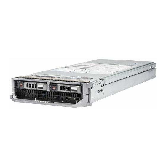
Dell PowerEdge M630 overview The Dell PowerEdge M630 is a half-height blade supported on the PowerEdge M1000e and PowerEdge VRTX enclosure and support upto: • One or two Intel Xeon E5-2600 v3 or E5-2600 v4 processors • 24 DIMMs •... -
Page 8: Front Panel
Figure 1. M630 configuration overview Front panel The features on the front panel include USB management port, iDRAC Direct LED indicator, sled handle and status indicator. -
Page 9: 2.5-Inch Hard Drive Or Ssd System
The USB management port can function asaregular USB1 or iDRAC managed USB port or provide access to the iDRAC features. USB port For more information, see the Dell Integrated Dell Remote Access Controller User's Guide at Dell.com/ idracmanuals. Management indicator The management indicator turns on when iDRAC controls the USB1 port for management functions. -
Page 10: 1.8-Inch Ssd System
The USB management port can function asaregular USB1 or iDRAC managed USB port or provide access to the iDRAC features. USB port For more information, see the Dell Integrated Dell Remote Access Controller User's Guide at Dell.com/ idracmanuals. Management indicator The management indicator turns on when iDRAC controls the USB1 port for management functions. -
Page 11: Diagnostic Indicators
Diagnostic Indicators The diagnostic indicators on the system front panel display error status during system startup. iDRAC Direct LED indicator codes NOTE: The iDRAC Direct LED indicator does not turn on for the USB mode. Figure 4. iDRAC Direct LED indicator iDRAC Direct statusindicator Table 3. -
Page 12: Hard Drive Or Ssd Indicator Patterns
connect the USB drive restart the system enter the System Setup set the drive as first in the boot sequence The USB device is displayed in the boot order setup screen only if it is attached to the system before you run the System Setup. You can also select the boot device bypressing F11 during system start-up and selecting aboot device for the current boot sequence. -
Page 13: Locating Service Tag Of Your System
Alternatively, the information may be on a sticker on the chassis of the system. This information isused by Dell to route support calls to the appropriate personnel. -
Page 14: Documentation Resources
For information about updating drivers and firmware, see the Download firmware and driverssectioninthisdocument. Dell.com/openmanagemanuals Managing your system For information about the features of the Dell OpenManage Systems Management, see the Dell OpenManage Systems Management Overview Guide. Dell.com/openmanagemanuals For information about setting up, using, and troubleshooting OpenManage, see the Dell OpenManage Server Administrator User’s Guide. - Page 15 Task Document Location Dell.com/DSET For information about installing and using Dell System E-Support Tool (DSET), see the Dell System E-Support Tool (DSET) User's Guide. Dell.com/asmdocs For information about installing and using Active System Manager (ASM), see the Active System Manager User’s Guide.
-
Page 16: Technical Specifications
PowerEdge M630 Processor specifications The PowerEdge M630 system supports up one or two Intel Xeon E5-2600 v3 or E5-2600 v4 product family processors. CAUTION: For processors of 105 W, 120 W, or 135 W, use heat sinks of 68 mm width. -
Page 17: System Battery Specifications
The PowerEdge M630 system supports PERC H330, PERC H730P, and PERC H730. PCIemezzaninecardslots The PowerEdge M630 system supports TwoPCIe x8 Gen 3 slots mezzanine card supporting dual port 10 Gb Ethernet, quad port 1 Gb, FC8 Fibre Channel, FC16 Fibre Channel, or Infiniband mezzanine cards... -
Page 18: Flash Drive
Flash drive The PowerEdge M630 system supports internal optional USB, internal optional SD card and optional vFlash card (with integrated iDRAC8 Enterprise). Ports and connectors specifications USB ports The PowerEdge M630 system supports: • USB 2.0-compliant ports on the front panel •... -
Page 19: Particulate And Gaseous Contamination Specifications
Table 11. Relative humidity specifications Relative humidity Specifications Storage 5% to 95% RH with 33°C (91°F) maximum dew point. Atmosphere must be noncondensing always. Operating 10% to 80% Relative Humidity with 29°C (84.2°F) maximum dew point. Table 12. Maximum vibration specifications Maximum vibration Specifications Operating... -
Page 20: Expanded Operating Temperature
Particulatecontamination Specifications NOTE: This condition applies only to data center environments. Air filtration requirements do notapplyto IT equipment designed to be used outside a data center, in environments such as an office or factory floor. NOTE: Air entering the data center must have MERV11 or MERV13filtration. -
Page 21: Expanded Operating Temperature Restrictions
– If you install a blade with twoprocessors in the M1000e enclosure, all blade slots in the enclosure must have PowerEdge M630 blades with the same configuration (PowerEdge M630 blades withtwoprocessors). However, vacant blade slots in the enclosure can be installed with blade blanks. -
Page 22: Initial System Setup And Configuration
Installing a blade iDRAC configuration The Integrated Dell Remote Access Controller (iDRAC) is designed to make system administrators more productive and improve the overall availability of Dell systems. iDRAC alerts administrators to system issues, helps them perform remote system management, and reduces theneed for physical access to thesystem. -
Page 23: Options To Install The Operatingsystem
The default user name and password are root and calvin. You can also log in by using Single Sign-On or Smart Card. NOTE: You must have iDRAC credentials to log in to iDRAC. For more information about logging in to iDRAC and iDRAC licenses, see the Integrated Dell Remote Access Controller User's Guide at Dell.com/idracmanuals. - Page 24 Downloading the drivers and firmware Dell recommends that you download and install the latest BIOS, drivers, and systems management firmware on your system. Prerequisite Ensure that you clear the web browser cache before downloading the drivers and firmware. Steps Go to Dell.com/support/drivers.
-
Page 25: Pre-Operating System Management Applications
Options to manage the pre-operating system applications Your system has the following options to manage the pre-operating system applications: • System Setup • Boot Manager • Dell Lifecycle Controller • Preboot Execution Environment (PXE) Related links System Setup Boot Manager Dell Lifecycle Controller... -
Page 26: System Setup Details
The iDRAC settings utility is an interface to set up and configure the iDRAC parameters by using UEFI (Unified Extensible Firmware Interface). You can enable or disable various iDRAC parameters by using the iDRAC settings utility. For more information about this utility, see Integrated Dell Remote Access Controller User’s Guide at Dell.com/idracmanuals. - Page 27 NOTE: If your operating system begins to load before you press F2, wait for the system to finish booting, and then restart your system and try again. On the System Setup Main Menu screen, click System BIOS. Related links System BIOS System BIOS Settings details System BIOS Settings details The System BIOS Settings screen details are explained as follows:...
- Page 28 NOTE: If your operating system begins to load before you press F2, wait for the system to finish booting, and then restart your system and try again. On the System Setup Main Menu screen, click System BIOS. On the System BIOS screen, click Boot Settings. Related links Boot Settings Boot Settings details...
- Page 29 NOTE: For the latest information about supported operating systems, go to Dell.com/ossupport. Related links Boot Settings Boot Settings details Viewing Boot Settings Changing the boot order You may have to change the boot order if you want to boot from a USB key or an optical drive. The following instructions may vary if you have selected BIOS for Boot Mode.
- Page 30 Option Description PXE Device n Enables you to control the configuration of the PXE device. Settings(n= 1 to 4) Related links Network Settings Viewing Network Settings System Security Youcan use the System Security screen to perform specific functions such as setting the system password, setup password and disabling the power button.
- Page 31 Option Description TPM Status Specifies the TPM status. TPM Command CAUTION: Clearingthe TPMresultsinthelossofallkeysinthe TPM. ThelossofTPMkeysmay affect booting to the operating system. Clears all the contents of the TPM. The TPM Clear option is set to No by default. Intel TXT Enablesordisablesthe IntelTrustedExecution Technology(TXT) option.Toenable the IntelTXToption, virtualization technologyand TPM Securitymust be enabled with Pre-boot measurements.
- Page 32 Option Description Forbidden Imports, exports, deletes, or restores entries in the Forbidden Signature Database (dbx). Signature Database Creating a system and setup password Prerequisite Ensure that the password jumper is enabled. The password jumper enables or disables the system password and setup password features.
- Page 33 Deleting or changing system and setup password Prerequisite NOTE: You cannot delete or change an existing system or setup password if the Password Status is set to Locked. Steps Toenter System Setup, press F2 immediately after turning onorrestarting your system. On the System Setup Main Menu screen, click System BIOS →...
- Page 34 On the System BIOS screen, click System Information. Related links System Information System Information details The System Information screen details are explained as follows: Option Description System Model Specifies the system model name. Name System BIOS Specifies the BIOS version installed on the system. Version System Specifies the current version of the Management Engine firmware.
- Page 35 Specifies the memory operating mode. The options available are Optimizer Mode, Advanced ECC Mode, Mode Mirror Mode, Spare Mode, Spare with Advanced ECC Mode, Dell Fault Resilient Mode and Dell NUMA Fault Resilient Mode. This option is set to Optimizer Mode by default.
- Page 36 Viewing Processor Settings To view the Processor Settings screen, perform the following steps: Turn on, or restart your system. Press F2 immediately after you see the following message: F2 = System Setup NOTE: If your operating system begins to load before you press F2, wait for the system to finish booting, and then restart your system and try again.
- Page 37 Description X2Apic Mode Enables or disables the X2Apic mode. Dell Controlled Controls the turbo engagement. Enable this option onlywhen System Profile is set to Performance. Turbo NOTE: Depending on the number of installed CPUs, there may be up to four processor listings.
- Page 38 SATA Settings details The SATA Settings screen details are explained as follows: Option Description Embedded SATA Enables the embedded SATAoption to be set to Off, ATA, AHCI, or RAID modes. This option is set to AHCI by default. Security Freeze Sends Security Freeze Lock command to the Embedded SATA drives during POST.
- Page 39 Option Description Option Description Capacity Specifies the total capacity of the hard drive. This field is undefined for removable media devices such as optical drives. Port E Sets the drive type of the selected device. For Embedded SATAsettings in ATAmode, set this field to Auto to enable BIOS support.
- Page 40 Option Description For AHCI or RAID mode, BIOS support is always enabled. Option Description Model Specifies the drive model of the selected device. Drive Type Specifies the type of drive attached to the SATA port. Capacity Specifies the total capacity of the hard drive. This field is undefined for removable media devices such as optical drives.
- Page 41 Option Description USB 3.0 Setting Enables or disables the USB 3.0support. Enable this option only if your operating system supports USB 3.0. If you disable this option, devices operate at USB 2.0speed. USB 3.0is enabled by default. User Accessible Enables or disables the USB ports. Selecting OnlyBack PortsOndisables the front USB ports, selecting All USB Ports Ports Off disables all USB ports.
- Page 42 Related links Serial Communication Serial Communication details Serial Communication details The Serial Communication screen details are explained as follows: Option Description Serial Enables the COM port or Console Redirection options. This option is set to Off by default. Communication Serial Port Address Enables you to set the port address for serial devices. This option is set to Serial Device 1=COM2, Serial Device 2=COM1 by default.
- Page 43 You can only change the rest of the options if the mode is set to Custom. This option is set to Performance Per Watt Optimized (DAPC) bydefault. DAPC is Dell Active Power Controller.
- Page 44 Related links System Profile Settings Viewing System Profile Settings Miscellaneous Settings Youcan use the Miscellaneous Settingsscreen to perform specific functions such as updating the asset tagandchanging the system date and time. Related links Miscellaneous Settings details System BIOS Viewing Miscellaneous Settings Viewing Miscellaneous Settings To view the Miscellaneous Settings screen, perform the following steps: Turn on, or restart your system.
-
Page 45: Idrac Settings Utility
NOTE: Accessing some of the features on the iDRAC settings utility needs the iDRAC Enterprise License upgrade. For more information about using iDRAC, see Dell Integrated Dell Remote Access Controller User's Guide at Dell.com/idracmanuals. Related links... -
Page 46: Dell Lifecycle Controller
Dell Lifecycle Controller Dell Lifecycle Controller (LC) provides advanced embedded systems management capabilities including system deployment, configuration, update, maintenance, and diagnosis. LC is delivered as part of the iDRAC out-of-band solution and Dell system embedded Unified Extensible Firmware Interface (UEFI) applications. -
Page 47: Pxe Boot
Menu item Description Launch Lifecycle Exits the Boot Manager and invokes the Dell Lifecycle Controller program. Controller System Utilities Enables you to launch System Utilities menu such as System Diagnostics and UEFI shell. Related links Boot Manager Viewing Boot Manager... -
Page 48: Installing And Removing Blade Components
Damage due to servicing that is not authorized by Dell is not covered by your warranty. Read and follow the safety instructions that are shipped with yourproduct. -
Page 49: Removing And Installing A Blade
Damage due to servicing that is not authorized by Dell is not covered by your warranty. Read and follow the safety instructions that are shipped with yourproduct. - Page 50 Figure 7. Removing and installing the I/O connector cover blade cover I/O connectorcover Figure 8. Removing or installing the blade release button blade enclosure Related links Safety instructions Installing a blade...
-
Page 51: Installing A Blade
Damage due to servicing that is not authorized by Dell is not covered by your warranty. Read and follow the safety instructionsthatcamewiththeproduct. -
Page 52: Installing The System Cover
Damage due to servicing that is not authorized by Dell is not covered by your warranty. Read and follow the safety instructionsthatcamewiththeproduct. - Page 53 Figure 10. Installing the system cover alignment guides on the system cover and the chassis system cover release button I/O connectorcover Next step Follow the procedure listed in the After working inside your system section. Related links Safety instructions Removing the system cover...
-
Page 54: Inside The Blade
Inside the blade Figure 11. Inside the blade restore Serial Peripheral Interface (rSPI) card mezzanine card connector (2) Network Daughter Card (NDC) memory module (24) cooling shroud hard drive or SSD backplane processor 2 processor 1... -
Page 55: Cooling Shroud
Damage due to servicing that is not authorized by Dell is not covered by your warranty. Read and follow the safety instructionsthatcamewiththeproduct. -
Page 56: Processor Blank And Dimm Blank
Damage due to servicing that is not authorized by Dell is not covered by your warranty. Read and follow the safety instructionsthatcamewiththeproduct. -
Page 57: Installingaprocessoror Dimmblank
Damage due to servicing that is not authorized by Dell is not covered by your warranty. Read and follow the safety instructionsthatcamewiththeproduct. -
Page 58: System Memory
Figure 15. Installing a processor/DIMM blank processor or DIMM blank heat sink retention socket (4) standoff (4) Next step Follow the procedure listed in the After working inside your system section. Related links Safety instructions Installing a processor Removing a processor or DIMM blank Before working inside your system After working inside your system System memory... - Page 59 Table 21. Memory population — operating frequency for supported configuration DIMM Type DIMMs Populated Voltage Operating Frequency (in Maximum DIMM Rank Per Per Channel MT/s) Channel 2400, 2133, 1866 RDIMM 1.2 V Single rank or dual rank 2400, 2133, 1866 1866 2400, 2133, 1866 LRDIMM...
-
Page 60: General Memory Module Installation Guidelines
channel 2: memory sockets B3, B7, and B11 channel 3: memory sockets B4, B8, and B12 General memory module installation guidelines Your system supports Flexible Memory Configuration, enabling the system to be configured and run in any valid chipset architectural configuration. -
Page 61: Sample Memory Configurations
• Memory modules must be identical in size, speed, and technology. • DIMMs installed in memorysockets with white release levers must be identical and the same rule applies for sockets with black release levers. This ensures that identical DIMMs are installed in matched pair —for example, A1 with A2, A3 with A4, A5 with A6, and so on. - Page 62 System Capacity (in DIMM Size (in Number of Organization and DIMM Slot Population DIMMs Speed 2R x8, 2400 MT/s 1R x8, 2133 MT/s A1, A2, A3, A4, A5, A6 2R x8, 2133 MT/s A1, A2, A3, A4, A5, A6 2R x4, 2133 MT/s A1, A2, A3, A4, A5, A6 2R x4, 2133 MT/s A1, A2, A3, A4, A5, A6, A7, A8...
-
Page 63: Removing Memory Modules
Damage due to servicing that is not authorized by Dell is not covered by your warranty. Read and follow the safety instructions that are shipped with yourproduct. -
Page 64: Installing Memory Modules
Damage due to servicing that is not authorized by Dell is not covered by your warranty. Read and follow the safety instructions that are shipped with yourproduct. -
Page 65: I/O Module Mezzanine Cards
The blade supports avariety of optional mezzanine cards. If installed, the mezzanine card(s) must be used inconjunction with a matching I/O module(s). For more information about I/O modules, see "Guidelines for Installing I/O Modules" in the M1000e Enclosure Owner's Manual at Dell.com/poweredgemanuals. Mezzanine card installation guidelines The blade supports two mezzanine cards: •... -
Page 66: Removing The Mezzanine Card
Damage due to servicing that is not authorized by Dell is not covered by your warranty. Read and follow the safety instructionsthatcamewiththeproduct. -
Page 67: Installing The Mezzanine Card
Damage due to servicing that is not authorized by Dell is not covered by your warranty. Read and follow the safety instructionsthatcamewiththeproduct. -
Page 68: Internal Dual Sd Module (Optional)
Damage due to servicing that is not authorized by Dell is not covered by your warranty. Read and follow the safety instructions that are shipped with yourproduct. - Page 69 Figure 21. Replacing an SD card IDSDM card SD card Figure 22. Installing an SD card IDSDM card SD card Next steps Followthe procedure listed inthe After working inside your system section. Enter the System Setup and ensure that the Internal SD Card Port and Internal SD Card Redundancy mode is enabled. Check if the new SD cardis functioning properly.
-
Page 70: Internal Usb Key
Damage due to servicing that is not authorized by Dell is not covered by your warranty. Read and follow the safety instructionsthatcamewiththeproduct. -
Page 71: Removing The Optional Idsdm Card
Damage due to servicing that is not authorized by Dell is not covered by your warranty. Read and follow the safety instructionsthatcamewiththeproduct. -
Page 72: Installingtheoptionalidsdmcard
Damage due to servicing that is not authorized by Dell is not covered by your warranty. Read and follow the safety instructionsthatcamewiththeproduct. -
Page 73: Rspi Card (Optional)
CAUTION: To prevent damage to the IDSDM card, you must hold the card only by its edges. Steps Align the following: • The slot on the card edge with the projection tabs on the mezzanine card support. • The two screw holes on the IDSDM card with the standoffs on the system board. •... -
Page 74: Removing The Optional Rspi Card
Damage due to servicing that is not authorized by Dell is not covered by your warranty. Read and follow the safety instructionsthatcamewiththeproduct. -
Page 75: Installing The Optional Rspi Card
Damage due to servicing that is not authorized by Dell is not covered by your warranty. Read and follow the safety instructionsthatcamewiththeproduct. -
Page 76: Replacing The Sd Vflash Card
Damage due to servicing that is not authorized by Dell is not covered by your warranty. Read and follow the safety instructionsthatcamewiththeproduct. -
Page 77: Network Daughter Card
Damage due to servicing that is not authorized by Dell is not covered by your warranty. Read and follow the safety instructionsthatcamewiththeproduct. - Page 78 Followthe procedure listed in the Beforeworking inside yoursystem section. Remove the mezzanine card. Steps Remove the two screws that secure the Network Daughter Card (NDC) to the system board. CAUTION: Toprevent damage to the NDC, you must hold the card only by its edges. Lift the card from the system board.
-
Page 79: Installing The Network Daughter Card
Damage due to servicing that is not authorized by Dell is not covered by your warranty. Read and follow the safety instructionsthatcamewiththeproduct. -
Page 80: Processors
Damage due to servicing that is not authorized by Dell is not covered by your warranty. Read and follow the safety instructionsthatcamewiththeproduct. -
Page 81: Removing A Processor
Damage due to servicing that is not authorized by Dell is not covered by your warranty. Read and follow the safety instructionsthatcamewiththeproduct. - Page 82 NOTE: The processor and heat sink can become extremely hot. Be sure that the processor has had sufficient time to cool before handling. Follow the safety guidelines listed in safety instructions section. Keep the Phillips #2 screwdriver ready. Followthe procedure listed in the Beforeworking inside yoursystem section. Remove the cooling shroud.
- Page 83 Figure 35. Installing and removing a processor socket-release lever 1 pin–1cornerof the processor processor slot (4) processor shield socket-release lever2 processor socket tab (4) Example Enter an example that illustrates the current task (optional). Next steps Replace theprocessor(s). Install the heatsink. Reinstall the cooling shroud.
-
Page 84: Installing A Processor
Damage due to servicing that is not authorized by Dell is not covered by your warranty. Read and follow the safety instructionsthatcamewiththeproduct. -
Page 85: Installing A Heat Sink
Damage due to servicing that is not authorized by Dell is not covered by your warranty. Read and follow the safety instructionsthatcamewiththeproduct. - Page 86 Figure 37. Applying thermal grease on the top of the processor 1. processor 2. thermal grease 3. thermal-grease syringe NOTE: The thermal-grease is intended for one-time use only. Dispose of the syringe after you use it. c. Place the heat sink onto the processor. d.
-
Page 87: Hard Drives Or Ssds
Related links Safety instructions Before working inside your system Removing the cooling shroud Installing a processor Installing the cooling shroud After working inside your system Hard drives or SSDs A hard disk drive (HDD), is a data storage device used for storing and retrieving digital information using one or more rigid rapidly rotating disks coated with magnetic material. -
Page 88: Removing A Hard Drive Or Ssd
Damage due to servicing that is not authorized by Dell is not covered by your warranty. Read and follow the safety instructionsthatcamewiththeproduct. -
Page 89: Installing A Hard Drive Or Ssd
Figure 41. Removing a SSD release button SSD carrier handle Next step If you are removing a hard drive or SSD permanently, install the hard drive or SSDblank. If you are installing anewhard drive or SSD, see the Installing the hard drive or SSD section. Related links Safety instructions Installing a hard drive or SSD... -
Page 90: Removing A Hard Drive Or Ssd Blank
Damage due to servicing that is not authorized by Dell is not covered by your warranty. Read and follow the safety instructionsthatcamewiththeproduct. -
Page 91: Installing A Hard Drive Or Ssd Blank
Step Press the release latch and slide the hard drive or SSD blank out of the hard drive or SSD slot. Figure 44. Removing a 2.5-inch hard drive hard drive or SSD blank release latch Figure 45. Removing a 1.8-inch SSD blank SSD blank release latch Next step... -
Page 92: Shutdown Procedure For Servicing A Hard Drive Or Ssd
Step Insert the hard drive or SSD blank into the hard drive or SSD slot until the release latch clicks into place. Figure 46. Installing a 2.5-inch hard drive blank hard drive or SSD blank release latch Figure 47. Installing a 1.8-inch SSD blank SSD blank release latch Related links... -
Page 93: Configuring The Boot Drive
Damage due to servicing that is not authorized by Dell is not covered by your warranty. Read and follow the safety instructionsthatcamewiththeproduct. -
Page 94: Installing A 2.5-Inch Hard Drive Or Ssd In A 2.5-Inch Hard Drive Or Ssd Carrier
Damage due to servicing that is not authorized by Dell is not covered by your warranty. Read and follow the safety instructionsthatcamewiththeproduct. -
Page 95: Removing A 1.8-Inch Ssd From A 1.8-Inch Ssd Carrier
Damage due to servicing that is not authorized by Dell is not covered by your warranty. Read and follow the safety instructionsthatcamewiththeproduct. -
Page 96: Removing The Hard Drive Or Ssd Cage
Damage due to servicing that is not authorized by Dell is not covered by your warranty. Read and follow the safety instructionsthatcamewiththeproduct. -
Page 97: Installing The Hard Drive Or Ssd Cage
Damage due to servicing that is not authorized by Dell is not covered by your warranty. Read and follow the safety instructionsthatcamewiththeproduct. -
Page 98: Hard Drive Or Ssd Backplane
Damage due to servicing that is not authorized by Dell is not covered by your warranty. Read and follow the safety... - Page 99 CAUTION: Toprevent damage to the hard drives or SSDs and the hard drive or SSD backplane, you must remove the hard drives or SSDs from the blade before removing the hard drive or SSD backplane. CAUTION: Note the number of each hard drive or SSD and temporarily label them before removal so that you can replace theminthesamelocations.
-
Page 100: Installing The Hard Drive Or Ssd Backplane
Damage due to servicing that is not authorized by Dell is not covered by your warranty. Read and follow the safety instructionsthatcamewiththeproduct. - Page 101 Remove the hard drive or SSD. . Remove the hard drive or SSD backplane. Steps Align the retention screws on the hard drive or SSD backplane cable connector withthe screw holes on the system board connector. Tighten the two retention screws to secure the backplane cable connector on the system board. Install the hard drive or SSD cage.
-
Page 102: System Board
Damage due to servicing that is not authorized by Dell is not covered by your warranty. Read and follow the safety... - Page 103 Follow the safety guidelines listed in safety instructions section. Keep the Phillips #2 screwdriver and the Hex nut driver-5 mm ready. Followthe procedure listed in the Beforeworking inside yoursystem section. Remove the following: Processor(s) and heat sink(s) Memory modules Coolingshroud Hard drive or SSDs Hard drive or SSD backplane Hard drive or SSD cage...
- Page 104 Figure 58. Removing the system board hex nut screw (4) system board screw (10) system board handle Next steps Install the systemboard. Followthe procedure listed inthe After working inside your system section.
-
Page 105: Installing The System Board
Damage due to servicing that is not authorized by Dell is not covered by your warranty. Read and follow the safety instructionsthatcamewiththeproduct. - Page 106 Figure 59. Installing the system board hex nut screw (4) system board screw (10) system board handle Next steps Install the following: Internal USB key SD vFlash card IDSDM or rSPI card mezzanine cards PCIe extender or storage controller card Hard drive or SSD cage Hard drive or SSD backplane Hard drive(s) or SSD(s)
- Page 107 Followthe procedure listed inthe After working inside your system section. Import your new or existing iDRAC Enterprise license. For more information, see the iDRAC8 User's Guide at Dell.com/ idracmanuals. Ensure that you: Use the Easy Restore feature torestorethe Service Tag.For more information, see the Restoring the Service Tagbyusing Easy Restore section.
-
Page 108: Trusted Platform Module
Damage due to servicing that is not authorized by Dell is not covered by your warranty. Read and follow the safety instructionsthatcamewiththeproduct. -
Page 109: Initializing The Tpm For Bitlocker Users
Figure 60. Installing the TPM TPM connector slot on the TPM connector plastic bolt slot on the system board Next steps Install the systemboard. Followthe procedure listed inthe After working inside your system section. Related links Safety instructions System board connectors Initializing the TPM for BitLocker users Initialize the TPM. -
Page 110: Nvram Backup Battery
Damage due to servicing that is not authorized by Dell is not covered by your warranty. Read and follow the safety instructions that are shipped with yourproduct. - Page 111 Figure 61. Removing the NVRAM backup battery positive side of battery negative side of battery connector Figure 62. Installing the NVRAM backup battery positive side of battery negative side of battery connector Next steps Install the following: System board IDSDM or rSPI card mezzanine cards Hard drive or SSD cage Hard drive or SSD backplane...
-
Page 112: Storage Controller Card Or Pcie Extender Card
Damage due to servicing that is not authorized by Dell is not covered by your warranty. Read and follow the safety instructions that are shipped with yourproduct. -
Page 113: Installing The Pcie Extender Or Storage Controller Card
Damage due to servicing that is not authorized by Dell is not covered by your warranty. Read and follow the safety... - Page 114 NOTE: PCIe extender or storage controller card is supported on systems with the SAS backplanes. NOTE: You must remove the PCIe extender or storage controller card to replace a faulty PCIe extender or storage controllercardorserviceothercomponentsinsidethesystem. Follow the safety guidelines listed in safety instructions section. Keep the Phillips #2 screwdriver ready.
- Page 115 Followthe procedure listed inthe After working inside yoursystemsection.. Related links Safety instructions Removing the PCIe extender or storage controller card After working inside your system Installing a hard drive or SSD...
-
Page 116: Using System Diagnostics
Using system diagnostics If you experience a problem with your system, run the system diagnostics before contacting Dell for technical assistance. The purpose of running system diagnostics is to test yoursystem hardwarewithout requiring additional equipment or risking data loss. If you are unable to fix the problem yourself, service and support personnel can use the diagnostics results to help you solve the problem. -
Page 117: System Diagnostics Controls
Displays a time-stamped log of the results of all tests run on the system. This is displayed if at least one event description is recorded. For information about embedded system diagnostics, see the Dell Enhanced Pre-boot System Assessment User Guide at Dell.com/ support/home. -
Page 118: Jumpersandconnectors
Damage due to servicing that is not authorized by Dell is not covered by your warranty. Read and follow the safety instructionsthatcamewiththeproduct. -
Page 119: System Board Connectors
System board connectors Figure 65. System board connectors Table27.Systemboardconnectors Item Connector Description BATTERY Connector for the 3.0 V coin cell battery STORAGE Storage controller card connector B3, B7, B11, B4, B8, B12 Memory module sockets (processor 2) CPU2 Processor socket 2 CPU1 Processor socket 1 A1, A5, A9, A2, A6, A10... -
Page 120: Disabling A Forgotten Password
Damage due to servicing that is not authorized by Dell is not covered by your warranty. Read and follow the safety instructionsthatcamewiththeproduct. -
Page 121: Troubleshooting Your System
Damage due to servicing that is not authorized by Dell is not covered by your warranty. Read and follow the safety instructions that are shipped with yourproduct. -
Page 122: Troubleshooting Hard Drives
Damage due to servicing that is not authorized by Dell is not covered by your warranty. Read and follow the safety instructions that are shipped with yourproduct. -
Page 123: Troubleshooting Solid State Drives
Damage due to servicing that is not authorized by Dell is not covered by your warranty. Read and follow the safety instructions that are shipped with yourproduct. -
Page 124: Troubleshooting Processors
Damage due to servicing that is not authorized by Dell is not covered by your warranty. Read and follow the safety instructions that are shipped with yourproduct. -
Page 125: Troubleshooting The Nvrambackup Battery
Damage due to servicing that is not authorized by Dell is not covered by your warranty. Read and follow the safety instructions that are shipped with yourproduct. -
Page 126: Getting Help
Contacting Dell Dell provides several online and telephone-based support and service options. If you do not have an active internet connection, you can find contact information on your purchase invoice, packing slip, bill, or Dell product catalog. Availability varies by country and product, and some services maynot be available in your area. -
Page 127: Quick Resource Locator For M630
Quick Resource Locator for M630 Figure 66. Quick Resource Locator for M630... - Page 128 Appendix. Supported processor for M630 Memory Processor Core Clock (GHz) TDP(W) Speed(MHz) XeonE5-2620V3 1866 XeonE5-2623V4 2133 XeonE5-2698V4 2400 XeonE5-2698V3 2133 XeonE5-2680V4 2400 XeonE5-2643V3 2133 XeonE5-2650V4 2400 XeonE5-2609V4 1866 XeonE5-2680V3 2133 XeonE5-2658V3 2133 XeonE5-1650V4 2400 XeonE5-2667V4 2400 XeonE5-2630LV3 1866 XeonE5-2683V3 2133 XeonE5-2695V3 2133 XeonE5-2603V3...
- Page 129 XeonE5-2660V4 2400 XeonE5-2650LV4 2400 XeonE5-2697AV4 2400 XeonE5-2609V3 1600...
Need help?
Do you have a question about the PowerEdge M630 and is the answer not in the manual?
Questions and answers