Dell PowerEdge Use Manual
Using dell blade servers in a dell poweredge high availability cluster
Hide thumbs
Also See for PowerEdge:
- Troubleshooting manual (122 pages) ,
- User manual (56 pages) ,
- System management manual (28 pages)

Related Manuals for Dell PowerEdge


Summary of Contents for Dell PowerEdge
- Page 1 Dell™ PowerEdge™ Cluster Systems Using Dell Blade Servers in a Dell PowerEdge High Availability Cluster w w w . d e l l . c o m | s u p p o r t . d e l l . c o m...
- Page 2 Other trademarks and trade names may be used in this document to refer to either the entities claiming the marks and names or their products. Dell Inc. disclaims any proprietary interest in trademarks and trade names other than its own.
-
Page 3: Table Of Contents
Overview ......Supported PowerEdge Blade Server Cluster Components .... - Page 4 Cabling the Storage Systems ....Direct-Attached Cluster ....Network-Attached Cluster ... . . Installing the Operating System and Configuring Your Cluster .
-
Page 5: Introduction
Introduction This document provides information for installing and managing your Dell™ PowerEdge™ blade server in a Dell PowerEdge cluster system and specific information about clustering your PowerEdge blade server modules with supported Dell PowerVault™ and Dell|EMC storage systems. Use this document in conjunction with the Installation and Troubleshooting Guide for your supported Dell PowerEdge cluster solution. -
Page 6: Supported Poweredge Blade Server Cluster Components
(private network), the client network (public network), and an additional PowerEdge server enclosure. Multiple PowerEdge server enclosures can be connected together in a cluster configuration. For supported cluster configurations, see "Cabling Your Blade Cluster Hardware" on page 25. - Page 7 Figure 1-1 provides a front and back view of the PowerEdge 1855/1955 system. Figure 1-2 provides a front and back view of the PowerEdge M1000e system. Figure 1-1. PowerEdge 1855/1955 Server Enclosure Overview front view back view Introduction...
- Page 8 server module (10) power supply module (4) front-panel indicators blanks (2) Ethernet switch module or Ethernet 10 Ethernet switch module (2) or Ethernet pass-through module (not shown) (2) pass-through module (not shown) (2) I/O bay 1 11 I/O bay 4 I/O bay 3 12 I/O bay 2 KVM module...
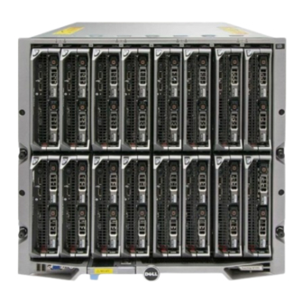
- Page 9 Figure 1-2. PowerEdge M1000e Server Enclosure Overview front view back view Introduction...
- Page 10 For information on supported cluster configurations, see "Cabling Your Blade Cluster Hardware" on page 25. For a list of supported hardware and software components, see the Platform Guide for your PowerEdge cluster solution located on the Dell Support website at support.dell.com.
- Page 11 The following is a list of features available on the DRAC/MC. Your system may have updates that enable additional features. Refer to the latest Dell Remote Access Controller/Modular Chassis User’s Guide on the Dell Support website at support.dell.com.
- Page 12 Ethernet ports, which can enable the use of NIC teaming on the cluster public network. For a list of supported Fibre Channel and iSCSI daughter cards, see the Platform Guide for your PowerEdge cluster located on the Dell Support website at support.dell.com. Introduction...
- Page 13 The server modules include two integrated Gigabit Ethernet network interface cards (NICs). You must configure at least two networks for each PowerEdge cluster solution. One cluster network is configured for heartbeat communications (private network) and is only accessible to the server modules in the cluster.
- Page 14 Fibre Channel Module You can configure the PowerEdge blade cluster with two hot-pluggable Fibre Channel switch modules installed on a PowerEdge 1855/1955 system or up to four hot-pluggable Fibre Channel switch/pass-through modules installed on the PowerEdge M1000e system to provide Fibre Channel connection between the server modules and storage system(s).
- Page 15 Additionally, the Fibre Channel switch module includes an internal serial port that communicates with the DRAC/MC module. The Fibre Channel switch module supports the following configurations: • Network-attached configuration with up to two supported Dell|EMC storage systems • Network-attached connection to an external storage area network (SAN)
-
Page 16: Supported Cluster Configurations
Supported Cluster Configurations The PowerEdge blade servers support both Fibre Channel and iSCSI cluster configurations using either Fibre Channel mezzanine cards or Gigabit Ethernet mezzanine cards to connect to the corresponding shared storage system in either direct-attached or network-attached environments. -
Page 17: Network-Attached Cluster
NOTE: Figure 1-4 through Figure 1-6 are for illustration only. Some cluster connections shown below are routed internally through the PowerEdge server enclosure. Figure 1-4. Network-Attached Cluster Connected to an External SAN Using Embedded Switch Modules... - Page 18 Figure 1-5. Network-Attached Cluster Connected to an External SAN Using Embedded Pass-Through Modules public network cluster node cluster node private network embedded pass- embedded pass- through module through module external switch external switch storage system Introduction...
-
Page 19: Blade Server Requirements
Figure 1-6. Network-Attached Cluster Connected to an External SAN Using Embedded Switch Modules public network private network cluster node cluster node embedded embedded switch module switch module inter-switch link inter-switch link external external switch switch storage system NOTE: It is recommended that you configure the paired inter-switch links (ISLs) as shown in Figure 1-6 for clusters with Fibre Channel storage systems. -
Page 20: Cluster Nodes
Table 1-4. Cluster Node Requirements Component Minimum Requirement Cluster nodes Two to eight PowerEdge server modules running the appropriate Windows Server 2003 operating system edition as described in Table 1-1 At least 512 MB of RAM installed per server module... -
Page 21: Cluster Storage
Table 1-5. Cluster Storage Requirements Storage Requirement Configuration Supported storage See the Platform Guide for your PowerEdge cluster solution on the Dell Support website at support.dell.com. Cluster shared If you are using either switch modules or pass-through storage modules to connect to network storage devices that are... -
Page 22: Other Documents You May Need
• The Dell PowerEdge system documentation provides information about system features, technical specifications, describes how to troubleshoot the PowerEdge server enclosure, and install or replace system components. • The Dell Remote Access Controller/Modular Chassis User’s Guide provides detailed information about using the remote management features of the system. - Page 23 Updates are sometimes included with the system to describe changes to the system, software, and/or documentation. NOTE: Always check for updates on the Dell Support website at support.dell.com and read the updates first because they often supersede information in other documents.
- Page 24 Introduction...
-
Page 25: Cabling Your Blade Cluster Hardware
NOTE: The cluster nodes represent the individual server modules in your Dell™ PowerEdge™ server enclosure. The designations namely, node 1 and node 2 and the server enclosure are used for illustrative purposes only. The system and the storage components in your cluster configuration may vary. - Page 26 Figure 2-1. Network Cabling Connection for PowerEdge M1000e Server Enclosure public network PowerEdge server enclosure public network Ethernet switch or node 2 pass-through module public NIC port private NIC port private NIC port public NIC port node 1 private network Ethernet switch or...
-
Page 27: Cabling The Private Network
Gigabit Ethernet pass-through module. Table 2-2 provides a cable connection matrix for configuring the private network using a Dell PowerConnect™ Ethernet switch or Gigabit Ethernet pass-through modules in your PowerEdge server enclosure. Table 2-2. Cabling the Private Network... -
Page 28: Cabling The Public Network
Cluster Configuration Private Network Configuration Gigabit Ethernet Two nodes in one or Connect a standard Ethernet cable to the pass-through two PowerEdge server corresponding cluster node ports on the module enclosure(s). Ethernet pass-through module. Connect a standard Ethernet cable from... -
Page 29: Cabling The Storage Systems
NOTE: The cluster nodes represent the individual server modules in the PowerEdge server enclosure. The designations namely, node 1 and node 2 and the server enclosure are used for illustrative purposes only. The system and the storage components in your cluster configuration may vary. - Page 30 Figure 2-2 shows an example of a direct-attached, two-node cluster configuration using redundant connections to server modules 5 and 6. See your Dell PowerEdge system documentation for more information about the Fibre Channel/Ethernet pass-through module. Cabling One PowerEdge Cluster to a Dell|EMC CX3-10c Storage System...
- Page 31 Figure 2-2. Direct-Attached Cluster Configuration Using CX3-10c Storage System public network PowerEdge server enclosure CX3-10c storage system 0 iSCSI 1 iSCSI 0 iSCSI 1 iSCSI 2 Fibre 3 Fibre 2 Fibre 3 Fibre iSCSI connection management connection Ethernet pass-through module 2...
-
Page 32: Network-Attached Cluster
4 Connect a cable from Fibre Channel switch module 2 to SP-B fibre port 0 (first fibre port). Figure 2-3 shows how to cable a PowerEdge M1000e sever enclosure to the CX3-20 storage system. The server module’s dual-port Fibre Channel daughter card and Fibre Channel switch modules are connected internally in the system chassis. - Page 33 Figure 2-3. Cabling One PowerEdge M1000e Server Enclosure to the CX3-20 Storage Processor Enclosure (SPE) PowerEdge system CX3-20 storage system Fibre Channel switch module in I/O Fibre Channel switch module in I/O bay C1 bay C2 SP-B SP-A 0Fibre 0Fibre...
- Page 34 In Figure 2-4, a PowerEdge 1855/1955 server enclosure is connected to the Dell|EMC iSCSI storage systems. The server and storage components in your configuration may vary. Figure 2-4. One PowerEdge 1855/1955 Server Enclosure Cabled to Two Storage Systems PowerEdge system...
- Page 35 Cabling One PowerEdge Server Enclosure to a Tape Library To provide additional backup for your cluster, you can add a tape backup device to your cluster configuration. The Dell PowerVault™ tape libraries contain an integrated Fibre Channel bridge or a storage network controller (SNC) that connects directly to your Dell|EMC Fibre Channel switch.
- Page 36 For high availability, each PowerEdge server enclosure requires direct paths to the attached storage systems. This configuration ensures that all running applications are available if one of the PowerEdge server enclosures needs to be shut down for maintenance. Figure 2-6 shows two PowerEdge 1855/1955 server enclosures cabled to one supported Dell|EMC storage system in an iSCSI configuration.
- Page 37 Figure 2-6. Cluster Configuration Using Two PowerEdge Server Enclosures and One Storage System public network private network connection ISLs ISLs PowerEdge system 1 PowerEdge system 2 storage system SPs Ethernet switch module for iSCSI Ethernet switch module for cluster traffic (2)
- Page 38 Figure 2-7. Two PowerEdge Server Enclosures Connected to Two Storage Systems public network private network connection ISLs ISLs PowerEdge system 1 PowerEdge system 2 storage system 2 SPs storage system 1 SPs Fibre Channel switch module (2) Fibre Channel switch module (2)
- Page 39 Network-Attached Cluster Connected to an External Fabric External Switches incorporate the external switch network or SAN connected to the PowerEdge Enclosure through the pass-through modules or switch modules. These configurations allow you to extend the Fibre Channel/iSCSI network by connecting more storage systems. The following sections provide examples for these configurations.
- Page 40 Figure 2-8. External Network-Attached iSCSI Cluster With Embedded Ethernet Pass-Through Modules public network storage processors Ethernet pass-through module Ethernet pass-through module port 5 port 5 port 4 port 4 Internal connections Cabling Your Blade Cluster Hardware...
- Page 41 Cabling PowerEdge Server Enclosures With Embedded Switch Modules to an External Fabric Figure 2-9 shows an example of a PowerEdge M1000e system cluster with embedded Fibre Channel switch modules connected to an external SAN-attached fabric.
- Page 42 Figure 2-9. External Network-Attached Cluster With Embedded Fibre Channel Switch Modules PowerEdge M1000e system CX3-80 storage system Fibre Channel switch module in I/O Fibre Channel switch module in I/O bay C1 bay C2 Cabling Your Blade Cluster Hardware...
-
Page 43: Installing The Operating System And Configuring Your Cluster
Your Cluster For information about installing the operating system, Microsoft Cluster Services, and configuring your cluster, see the Installation and Troubleshooting Guide for your cluster system located on the Dell Support website at support.dell.com. Maintaining Your Cluster For information about maintaining your cluster, see the Installation and Troubleshooting Guide for your cluster system located on the Dell Support website at support.dell.com. - Page 44 Cabling Your Blade Cluster Hardware...
Need help?
Do you have a question about the PowerEdge and is the answer not in the manual?
Questions and answers