AEMC Simple Logger II Series User Manual
Voltage and current data loggers
Hide thumbs
Also See for Simple Logger II Series:
- Quick start manual (8 pages) ,
- User manual (48 pages)
Table of Contents
Advertisement
Quick Links
Download this manual
See also:
User Manual
Advertisement
Table of Contents

Related Manuals for AEMC Simple Logger II Series


Summary of Contents for AEMC Simple Logger II Series
- Page 1 VOLTAGE AND CURRENT DATA LOGGERS Simple Logger ® Series E N G L I S H User Manual...
- Page 2 The recommended calibration interval for this instrument is 12 months and begins on the date of receipt by the customer. For recalibration, please use our calibration services. Refer to our repair and calibration section at www.aemc.com. Serial #: ________________________________ Catalog #: _______________________________ Model #: ________________________________...
-
Page 3: Table Of Contents
Table of Contents 1. INTRODUCTION ................3 1.1 International Electrical Symbols ..........3 1.2 Definition of Measurement Categories ........4 1.3 Receiving Your Shipment ............4 1.4 Ordering Information ..............4 1.4.1 Recommended Probes for Models L101/L102/L562 ..5 1.4.2 Recommended Probes for Model L111 ......5 1.4.3 Accessories and Replacement Parts ......6 2. PRODUCT FEATURES ..............7 2.1 Description ................7 2.2 Control Features ...............8 3. - Page 4 APPENDIX A: TROUBLESHOOTING ............28 APPENDIX B: GLOSSARY ..............29 Repair and Calibration ................30 Technical and Sales Assistance ............30 Limited Warranty ...................31 Warranty Repairs ...................31...
-
Page 5: Introduction
CHAPTER 1 INTRODUCTION WARNING These safety warnings are provided to ensure the safety of personnel and proper operation of the instrument. • Read the instruction manual completely and follow all the safety infor- mation before attempting to use or service this instrument. • Never exceed the maximum working voltage ratings given. • NEVER open the back of the instrument while connected to any circuit or input. • Always inspect the instrument accessories and leads prior to use. Replace any defective parts immediately with factory parts. International Electrical Symbols Signifies that the instrument is protected by double or reinforced insulation. Indicates a WARNING and that the operator must refer to the user manual for instructions before operating the instrument. -
Page 6: Definition Of Measurement Categories
Definition of Measurement Categories Cat. I: For measurements on circuits not directly connected to the AC supply wall outlet such as protected secondaries, signal level, and limited energy circuits. Cat. II: For measurements performed on circuits directly connected to the electrical distribution system. Examples are measurements on household appliances or portable tools. Cat. III: For measurements performed in the building installation at the distribution level such as on hardwired equipment in fixed installa- tion and circuit breakers. -
Page 7: Recommended Probes For Models L101/L102/L562
Simple Logger II Model L261 ........Cat. #2126.05 ® (1-Channel, TRMS 600V Includes USB cable, DataView CD-ROM, 2x1.5V AA-cell alkaline batteries, one set of leads, ® one set of alligator clips, user manual and warranty card. Simple Logger II Model L322 ........Cat. #2126.06 ®... -
Page 8: Accessories And Replacement Parts
Accessories and Replacement Parts Lead - Set of 2, Color-coded 5 ft w/color-coded alligator clips (Rated 600V Cat IV, 15A) ............ Cat. #2140.62 Lead - Set of 2, Color-coded 10 ft w/color-coded alligator clips (Rated 600V Cat IV, 15A) ............ Cat. #2140.63 Replacement - A to 5-pin mini-B 2M USB cable ....Cat. #2126.49 Fuse-Set of 5, 2A (250V) FA for SLII Model L111 ....Cat. #2126.48 Order Accessories and Replacement Parts Directly Online Check our Storefront at www.aemc.com/store for availability Simple Logger II Series ®... -
Page 9: Product Features
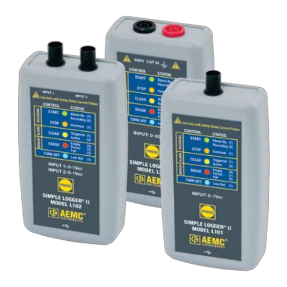
CHAPTER 2 PRODUCT FEATURES Description The Simple Logger II Series includes one and two channel recording ® devices (model dependent) powered by an alkaline battery pack. Line tracking is performed such that 64 samples over one line cycle are taken. Frequency tracking is performed over the range of ±2Hz around the nominal line frequency (50 or 60Hz). -
Page 10: Control Features
Control Features Figure 2-2. Key Components and Features 1. Input (model dependent) L101/L102 - BNC Input Termination L261/L111 - Two recessed 4mm safety banana jacks L322/L432 - One 4-position removable screw-type terminal block L562 - BNC/Two recessed 4mm safety banana jacks L642 - Two miniature thermocouple connectors 2. Five LED Indicators The LEDs on the logger serve two functions: Control Operation and Status Function. • The control operation (when holding down the PRESS button) is indicated with text to the left of each LED. - Page 11 ated with each LED is indicated with text to the right of each LED. • Refer to § 4.1 for detailed descriptions of each LED. 3. Control Button (PRESS) This button marked “PRESS” selects the mode of operation. Use this button to start or stop recordings, erase the memory, clear alarms and turn the instrument ON/OFF. 4. Female Type Mini-B USB Connector This connector is located on the bottom of the instrument. 5. Reset Switch (not shown) The RESET switch resets the CPU and is located under the top cover. To access this switch remove the battery compartment cover, then remove the four screws holding the two halves of the case together. The reset switch is located on the exposed PCB near the inputs. 6. Flash Upgrade Switches (not shown) These two switches (accessible from under the top cover), along with the RESET button (and PC software), are used to recover from a failed flash upgrade procedure.
-
Page 12: Specifications
CHAPTER 3 SPECIFICATIONS Reference Conditions: 23°C ± 3°C, 30 to 50% RH, DC or 50/60 Hz, battery voltage: 3V ± 10%. MODEL L101 L102 ELECTRICAL Channels Input Current Probe Output 0 to 1V Voltage Range Resolution 0.1mV Accuracy 0 to 10mV unspecified (50/60Hz) 10 to 50mV: ±(0.5% of Reading +1mV) 50 to 1000mV: ±(0.5% of Reading +0.5mV) Maximum Input Voltage*** 5Vrms (-7.07V to +7.07V... - Page 13 MODEL L111 ELECTRICAL Channels Input Two recessed banana jacks Current Probe Output 0 to 1A Current Range Resolution 0.1mA Accuracy 0 to 10mA unspecified (50/60Hz) 10 to 50mA: ±(0.5% of Reading +1mA) 50 to 1000mA: ±(0.5% of Reading +0.5mA) Maximum Input Voltage*** 1.2An (An=nominal current) Input Impedance Sample Rate...
- Page 14 MODEL L322 ELECTRICAL Channels Input One 4-position removable screw-type terminal block Measurement Range -20mA to 20mA Resolution 0.01mA Accuracy (0.25% of Reading +0.05mA) Input Impedance Sample Rate Maximum of 8 samples taken at storage interval Storage Rate Programmable from 125mS to 1 day Storage Modes Start/Stop, FIFO and Extended Recording Mode* (XRM ™...
- Page 15 MODEL L432 ELECTRICAL Channels Input One 4-position removable screw-type terminal block Measurement Range Range 1: -100mV to 100mV (3 ranges/channel) Range 2: -1V to 1V Range 3: -10V to 10V Resolution Range 1: 0.1mV Range 2: 1mV Range 3: 10mV Accuracy Range 1: ±(0.5% of Reading +1mV) (50/60Hz)
- Page 16 MODEL L562 ELECTRICAL Channels Connection Current Channel Voltage Channel Input Two recessed banana jacks Measurement Range 0 to 1V (for use with current 0 to 600V AC/DC probes with a voltage output) Resolution 0.1mV 0.1V Accuracy 0 to 10mV unspecified 0 to 5V unspecified 50 or 60 Hz 10 to 50mV:...
- Page 17 MODEL L642 ELECTRICAL Channels Input Two miniature thermocouple connectors Measurement Type: °F °C -346 to +2192 -210 to +1200 -328 to +2501 -200 to +1372 -418 to +752 -250 to +400 -328 to +2372 -200 to +1300 -238 to 1742 -150 to +950 32 to 3212 0 to 1767...
- Page 18 MODEL L261 ELECTRICAL Channels Input Two recessed banana jacks Voltage Range 0 to 600V Resolution 0.1V Accuracy 0 to 5V unspecified (50/60Hz) 5 to 50V: ±(0.5% of Reading +1V) 50 to 600V: ±(0.5% of Reading +0.5V) Maximum Input Voltage*** 1.2Vn (Vn=nominal voltage) Input Impedance 40MW Sample Rate...
-
Page 19: Operation
CHAPTER 4 OPERATION LED Control Operation and Status Function The ON/OFF state of the instrument can be determined by pressing the PRESS button for less than 0.5 seconds. If the instrument is ON, the status of the instrument will be shown by the LEDs. If the instrument is OFF no indication will be given (the LEDs will not blink). The instrument is turned ON by pressing the PRESS button until all LEDs light. At this point, the button can be released and the instrument will remain in the ON state. If the button is released before all the LEDs light (in unison), the instrument will remain in the OFF state. When holding the PRESS button while the instrument is ON, each LED will light in sequence. Continuing to hold the PRESS button until the last LED lights, turns the instrument OFF. At this point, releasing the button will result in no action being taken. This provides a mechanism to cancel (or ignore) the button press. Control of the instrument is performed by pressing and holding the PRESS button (while the instrument is ON) until the control LED corresponding to the desired operation lights. Releasing the button when the desired control LED is illuminated results in the corresponding operation being performed. - Page 20 The Control and Status Operation of each LED is as follows: GREEN LED: CONTROL STARTS A RECORDING Logger is turned OFF or in Low Power Standby state* STATUS Single-blink Logger is in Standby Mode (and not recording) Double-blink Logger is in Record Mode ORANGE LED: CONTROL STOPS A RECORDING Logger is not in an Overload condition STATUS Single-blink...
-
Page 21: Connecting The Simple Logger ® Ii To A Computer
• SLEEP mode: The instrument enters the low power state if the button is not pressed for one minute. It will remain in this state until either the button is pressed or the internal clock reaches the start time for a scheduled recording. • RECORD mode: The instrument enters the low power state between sample sets. The slower the storage rate, the greater the portion of time the instrument is in the low power state. Thus, the slower the storage rate, the longer the instrument can record. • OFF mode: The instrument enters the low power state and will turn on at the time a recording is scheduled. Connecting the Simple Logger II to a Computer ®... -
Page 22: Recording Data
The instrument contains protection circuitry to prevent it from being turned on when the battery voltage is below 1.7V. There are two thresholds for the battery voltage: • The first is used to indicate low battery. The low battery indicator will blink when the battery voltage drops below 1.8V. • The second is used to determine when to terminate recording and turn the unit off. The shutdown threshold is when the battery voltage drops below 1.7V. Recording Data NOTE: The Simple Logger II is factory configured and may be altered ® to fit the users needs (see the Configuring the Simple Logger II section ®... -
Page 23: Stopping A Recording Session
4.4.2 Stopping a Recording Session 1. Press and hold the PRESS button. When the STOP (ORANGE) LED lights up, release the button. 2. The GREEN LED will change from a double-blink to a single-blink, indicating STANDBY mode. The data will be retained, even if the instrument is turned OFF. The recorded data is stored in Flash memory (maintained even in the absence of batteries). The recorded data may be downloaded to a computer. Downloading Recorded Data Recorded measurements stored in the instrument are transferred to a computer via the download command in the SLII Control Panel. For instructions on downloading data, see the Downloading Recorded Instru-... -
Page 24: Erasing Data From Memory
Erasing Data from Memory Erasing data from the instrument’s memory can only be performed while in the STANDBY mode. There are two ways to erase the memory: Erasing the Memory using the PRESS Button: 1. Press and hold the PRESS button. When the ERASE (RED) LED lights up, release the button. This will arm the instrument for an erase operation (when not in record mode). While armed to erase memory, the RED LED will blink at a fast rate for a period of five seconds. 2. Press the PRESS button for another 0.5 seconds to complete the erase operation. -
Page 25: Trend Measurements
direct measurement, the result of complex mathematical operations on a single or multiple input, or other channels. Sample Rate: The rate at which the instrument measures inputs. Storage Rate: The rate at which channel measurements are stored. 4.8.1 Trend Measurements The logger stores the TRMS calculation of each of the inputs. In addition, the user can define the storage rate, recording period and measurement format using the Configure Instrument dialog box in the SLII Control Panel software. Trend measurements are stored at this fixed storage rate. Normal Operation When the instrument is turned ON, the following occurs (provided there is sufficient battery voltage and no data is stored in the instrument’s memory): • The GREEN LED single-blinks. (STANDBY mode is active and the logger is not recording). •... - Page 26 Event: Recording with a Partial or Full Memory If the RED LED is double-blinking, the memory must be erased before any further recording can be performed. If the RED LED is single-blinking prior to starting a New Recording Ses- sion, the memory is partially full. To save, clear or check memory availability, use the Simple Logger ® Control Panel software. There may be instances where the GREEN LED is also double-blinking indicating that the logger is still recording. The user can choose to stop the Recording Session and download the session and/or erase the memory. NOTE: The logger memory cannot be erased while in the Record mode. The recording must be stopped first.
-
Page 27: 4.10 Reset Switch Operation
voltage may rise slightly after the unit turns itself off. In this event, the unit may turn on momentarily as a result of a button press. The batteries must be replaced before the recorded session(s) can be downloaded from the instrument. NOTE: Replacing the batteries while the unit is OFF will not result in the loss of data memory. The internal backup capacitor will maintain the clock and memory while the main batteries are being replaced. - Page 28 NOTE: It is recommended to only press the RESET switch when the logger stops responding to a normal press button control when not connected to DataView . It is not recommended to reset the instrument when the logger is ® recording, downloading or being configured.
-
Page 29: Maintenance
CHAPTER 5 MAINTENANCE Use only factory specified replacement parts. AEMC will not be held ® responsible for any accident, incident, or malfunction following a repair done other than by its service center or by an approved repair center. Changing the Batteries WARNING: Turn the unit off before changing the batteries or loss of recorded data may occur. -
Page 30: Appendix A: Troubleshooting
APPENDIX A TROUBLESHOOTING Symptom: After being in a damp, cold environment, the logger does not function. Cause, Correction: Condensation may have formed inside the logger, shorting out the circuitry and discharging the battery. Allow the circuit board to dry thoroughly in a warm location. Symptom: Simple Logger II does not start recording. ® Cause, Correction: Make sure battery power is present. Make sure the PRESS button is pushed long enough to light the GREEN LED and released before the next LED lights. Make sure the RED LED is not double- blinking. If it is, memory is full and you need to erase the data (see § 4.7). -
Page 31: Appendix B: Glossary
APPENDIX B GLOSSARY Some general terminology associated with the data collection process is listed here for convenience. Bps: Bits Per Second, a unit of signal transfer speed equal to the number of elements per second. The Simple Logger II transfers data at ® the rate of 115200 bps. Button: An actual key on the logger or computer keyboard or a soft key in the program on the computer screen. Data logger: A device used to sample and store electrical signals representative of physical phenomena such as temperature, pressure and flow, for long periods of time in an unattended environment. Download: The process of transferring data from the logger to the computer. Hz: Hertz, a unit of measure of frequency equivalent to cycles per second. I/O: Input/output, a device or port capable of sending or receiving digital information. Port: A name given to any connector allowing input or output of information. Processor: A computing device used to calculate and run a set of instructions. Recording session: A recording session is defined as the time and data contained within the starting and ending of a recording. Resolution: The number of bits in which digitized values will be stored. Zoom: The ability to select a section of the graph and magnify it for better readability. USB: Universal Serial Bus, a communications port used to access the Data Logger via a computer program (Dataview ® Simple Logger II Series ®... -
Page 32: Repair And Calibration
For instrument repair and calibration: You must contact our Service Center for a Customer Service Authorization Number (CSA#). This will ensure that when your instrument arrives, it will be tracked and processed promptly. Please write the CSA# on the outside of the shipping container. If the instrument is returned for calibration, we need to know if you want a standard calibration, or a calibration traceable to N.I.S.T. (Includes calibration certificate plus recorded calibration data). Ship To: Chauvin Arnoux , Inc. d.b.a. AEMC Instruments ® ® 15 Faraday Drive Dover, NH 03820 USA Phone: (800) 945-2362 (Ext. 360) (603) 749-6434 (Ext. 360) -
Page 33: Limited Warranty
® For full and detailed warranty coverage, please read the Warranty Coverage Information, which is attached to the Warranty Registration Card (if enclosed) or is available at www.aemc.com. Please keep the Warranty Coverage Information with your records. What AEMC Instruments will do: ®... - Page 34 Notes: Simple Logger II Series ®...
- Page 36 10/08 99-MAN 100309 v5 Chauvin Arnoux , Inc. d.b.a. AEMC Instruments ® ® 15 Faraday Drive • Dover, NH 03820 USA • Phone: (603) 749-6434 • Fax: (603) 742-2346 www.aemc.com...
Need help?
Do you have a question about the Simple Logger II Series and is the answer not in the manual?
Questions and answers