Table of Contents
Advertisement
Quick Links
Download this manual
See also:
User Manual
Advertisement
Table of Contents

Related Manuals for AEMC PEL 105


Summary of Contents for AEMC PEL 105
- Page 1 Power & Energy Logger Model PEL 105 Quick Start Guide ENGLISH www.aemc.com...
-
Page 2: Statement Of Compliance
Statement of Compliance Chauvin Arnoux , Inc. d.b.a. AEMC Instruments ® ® certifies that this instrument has been calibrated using standards and instruments traceable to international standards. We guarantee that at the time of shipping your instrument has met its published specifications. -
Page 3: Product Packaging
• 9.6V NiMh Battery - installed • 8 GB SD-Card - installed • High Voltage Warning/Caution Card USB THUMB DRIVE: DataView software and the user manual for the PEL 105 are stored ® on the USB thumb drive supplied with the instrument. -
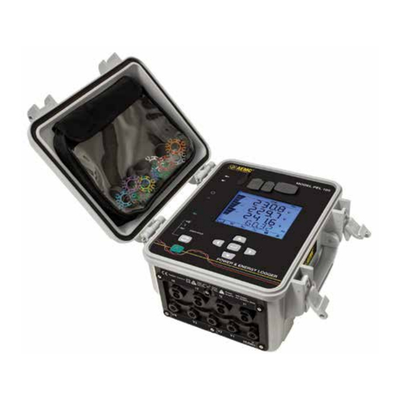
Page 4: Front Panel
Front Panel MODEL PEL 105 USB Port Ethernet Port Power Input External Power LED (Green) - ON: Instrument is currently running on external AC power. - OFF: Instrument is running on battery or phase power. Battery LED (Yellow/Red) - ON: Steady yellow: battery is actively charging. - Page 5 Phase Sequence (Red) - ON (blinks once per second): Phase rotation not as expected - OFF: Phase rotation order is as expected Overload LED (Red) - ON: At least one input is overloaded, or current inputs are mismatched. - OFF: No input overload. SD Card LED (Red/Green/Orange) - Steady red: SD card is locked, unrecognized, or not present.
-
Page 6: Turning The Instrument On/Off
Turning the Instrument ON/OFF The instrument can operate on three different sources of power: • External power provided by plugging into an AC outlet with the AC adapter. The instru- ment will always run on external AC power when plugged in, even if phase voltage power and/or battery power are also available. -
Page 7: Connecting To The Computer
Connecting to the Computer Before you can use the PEL Control Panel to communicate with your PEL 105, you must establish a connection between the instrument and the computer. There are six types of connections available: • USB cable connection •... -
Page 8: Wi-Fi Direct Connection
Wi-Fi Direct Connection Before you can connect through the PEL Control Panel, you must create a Wi-Fi connection between the computer and instrument in Microsoft Windows. A direct Wi-Fi connection requires the instru- ment’s SSID number and (if required) password, which you can define by connecting the instrument via USB cable, opening the Control Panel, and displaying the Configure dialog box, as instructed by the Control Panel Help. -
Page 9: Installing The Sd Card
Setting the Instrument Clock Before using the instrument, you should ensure the instrument clock is set to the correct time zone. By default the PEL 105 is set to Universal (UTC) time. To change this to another time zone, do the following: Open the PEL Control Panel and connect to the instrument, as instructed in the preceding sec- tion “Connecting to the Computer.”... - Page 10 • If the LED is green, the SD card is ready to store recordings. • If the LED glows steady red, ensure that: • The SD card is installed. • The write-protect sliding tab on the card is in the “unlock” position (towards the metal con- tacts).
- Page 11 The following hookup diagrams and connection instructions are for distribution systems sup- ported by the PEL 105. The instrument must be appropriately configured for the hookup type. Most configuration is performed through the PEL Control Panel, as described in the Help.
- Page 12 3-Phase 3-Wire Open ∆ (2 current probes) 3-Phase 3-Wire Open ∆ (3 current probes) (3P-3WO2) (3P-3WO3) • VE/GND test lead to ground • VE/GND test lead to ground • V1 test lead to L1 • V1 test lead to L1 •...
- Page 13 3-Phase 3-Wire ∆ Balanced 3-Phase 4-Wire Y (3P-4WY) (1 current probe) (3P3W∆b) • VE/GND test lead to ground • VE/GND test lead to ground • VN test lead to neutral (N) • V1 test lead to L1 • V1 test lead to L1 •...
- Page 14 3-Phase 4-Wire Open ∆ 3-Phase 4-Wire ∆ (3P-4W∆) • VE/GND test lead to ground • VE/GND test lead to ground • VN test lead to neutral (N) • VN test lead to neutral (N) • V1 test lead to L1 •...
- Page 15 DC 4-Wire (dC-4W) • VE/GND test lead to ground • VN test lead to the common conductor • V1 test lead to conductor +1 • V2 test lead to conductor +2 • V3 test lead to conductor +3 • IN probe to the common conductor •...
-
Page 16: Technical And Sales Assistance
If the instrument is returned for calibration, we need to know if you want a standard calibration, or a calibration traceable to N.I.S.T. (Includes calibration certificate plus recorded calibration data). Ship To: Chauvin Arnoux , Inc. d.b.a. AEMC Instruments ® ® 15 Faraday Drive Dover, NH 03820 USA Phone: (800) 945-2362 (Ext. - Page 17 Limited Warranty The Model PEL 105 is warranted to the owner for a period of two years from the date of original purchase against defects in manufacture. This limited warranty is given by AEMC Instruments, not by the distributor from ®...
- Page 18 Notes:...
- Page 20 06/18 99-MAN 100428 v4 Chauvin Arnoux , Inc. d.b.a. AEMC Instruments ® ® 15 Faraday Drive • Dover, NH 03820 USA • Phone: (603) 749-6434 • Fax: (603) 742-2346 www.aemc.com...
Need help?
Do you have a question about the PEL 105 and is the answer not in the manual?
Questions and answers