AEMC Simple Logger II Series User Manual
Trms clamp-on, ac current, ac voltage, dc current, dc voltage, thermocouple, temp/rh, event logger
Hide thumbs
Also See for Simple Logger II Series:
- Quick start manual (8 pages) ,
- User manual (36 pages)
Table of Contents
Advertisement
Quick Links
Advertisement
Table of Contents

Related Manuals for AEMC Simple Logger II Series


Summary of Contents for AEMC Simple Logger II Series
- Page 1 TRMS CLAMP-ON • AC CURRENT AC VOLTAGE • DC CURRENT DC VOLTAGE • THERMOCOUPLE TEMP/RH • EVENT LOGGER Simple Logger ® Data Loggers E N G L I S H User Manual GlobalTestSupply www. .com Find Quality Products Online at: sales@GlobalTestSupply.com...
- Page 2 Statement of Compliance Chauvin Arnoux , Inc. d.b.a. AEMC Instruments ® ® certifies that this instrument has been calibrated using standards and instruments traceable to international standards. We guarantee that at the time of shipping your instrument has met its published specifications.
-
Page 3: Table Of Contents
Table of Contents 1. INTRODUCTION ................. 4 1.1 Symbols Used ................5 1.2 Definition of Measurement Categories ........5 1.3 Receiving Your Shipment ............6 1.4 Ordering Information ..............6 1.4.1 Recommended Probes: Models L101/L102/L562 ..7 1.4.2 Recommended Probes: Model L111 ......8 1.4.3 Accessories and Replacement Parts ......8 2. PRODUCT FEATURES ................. 9 2.1 Description ................9 2.2 Control Features ..............10 2.2.1 Standard Models ............10 2.2.2 Clamp-on Model CL601 ..........12 3. - Page 4 4.8 Logger Operation ..............32 4.8.1 Recording with Memory Cleared ........32 4.8.2 Recording with a Partial or Full Memory .....32 4.8.3 Memory Filled During Recording Session ....33 4.8.4 Batt. Power Insufficient for Full Record Duration ..33 4.8.5 Recording Session has Ended ........34 4.9 Event Logger Operation (Model L404) ........34 4.9.1 Sample Event Capture ..........35 4.9.2 Application Examples ..........36 4.10 Reset Switch Operation ............36 4.11 Flash Upgrade Switches ............37 5. DATAVIEW SOFTWARE ..............38 5.1 Installing DataView ..............38 ® 5.2 Simple Logger II Control Panel ..........40 6.
-
Page 5: Introduction
CHAPTER 1 INTRODUCTION WARNING These instruments comply with safety standard EN 61010-1 (Ed 2-2001) or EN 61010-2-032 (2002) for voltages and categories of installation, at an altitude below 6562 ft (2000m) and indoors, with a degree of pollution at most equal to 2. • Do not use in explosive atmosphere or in the presence of flammable gases or fumes. • Do not use on voltage networks greater than categories mentioned above. • Observe the maximum voltages and intensities assigned between terminals and earth. • Do not use it if appears damaged, incomplete or improperly closed. • Before each use, check the condition of the insulation of cables, case and accessories. Anything which appears damaged (even partially) must be reported for repair or scrapping. -
Page 6: Symbols Used
Symbols Used Signifies that the instrument is protected by double or reinforced insulation. CAUTION - Risk of Danger! Indicates a WARNING and that the operator must refer to the user manual for instructions before operating the instrument in all cases where this symbol is marked. Risk of electric shock. -
Page 7: Receiving Your Shipment
Receiving Your Shipment Upon receiving your shipment, make sure that the contents are consistent with the packing list. Notify your distributor of any missing items. If the equipment appears to be damaged, file a claim immediately with the carrier and notify your distributor at once, giving a detailed description of any damage. Save the damaged packing container to substantiate your claim. Ordering Information Simple Logger II Model CL601 ........Cat. #2126.01 ®... -
Page 8: Recommended Probes: Models L101/L102/L562
Simple Logger II Model L432 ........Cat. #2126.07 ® (2-Channel, DC ±100mV / 1V / 10V Includes USB cable, one 4-position terminal block connector, DataView software, 2x1.5V ® AA alkaline batteries and quick start guide. Simple Logger II Model L481 ........Cat. #2126.25 ®... -
Page 9: Recommended Probes: Model L111
1.4.2 Recommended Probes for Model L111 AC Current Probe Model MN313 ..............Cat. #2116.25 (150A, 1mA/A, Lead) AC Current Probe Model SR604 ..............Cat. #2113.44 (1000A, 1mA/A, Lead) AC Current Probe Model JM830A ............Cat. #2110.83 (3000A, .333mA/A, Lead) AC Current Probe Model MN01 ..............Cat. #2129.17 (150A, 1mA/A, Lead) AC Current Probe Model MN02 ..........Cat. #2129.20 (100A, 1mA/A, Lead, 1% Accuracy) 1.4.3 Accessories and Replacement Parts 110V Outlet Adapter w/4mm Banana Plug ...... -
Page 10: Product Features
CHAPTER 2 PRODUCT FEATURES Description The Simple Logger II Series include one and two channel recording ® devices (model dependent) powered by alkaline batteries. For AC units, line tracking is performed such that 64 samples over one line cycle are taken. Frequency tracking is performed over the range of ±2Hz around the nominal line frequency (50 or 60Hz). Harmonic measurements are calculated from these 64 samples (harmonics are only available from the Simple Logger II Control Panel within the DataView... -
Page 11: Control Features
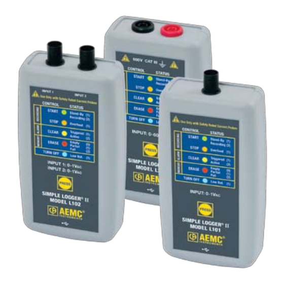
Control Features 2.2.1 Standard Models Figure 2-1 1. Input (model dependent) L101/L102 - BNC Input Termination L261/L481 - Two recessed 4mm safety banana jacks L111 - Two recessed 4mm safety banana jacks and fuse location L322/L432 - One 4-position removable screw-type terminal block L404 - One 8-position removable screw-type terminal block L562 - BNC/Two recessed 4mm safety banana jacks L642 - Two miniature thermocouple connectors L702 - Temp/RH Sensor ML912 - Two captive MiniFlex sensors ® Simple Logger ® II Series GlobalTestSupply www. - Page 12 2. Five LED Indicators The LEDs on the logger serve two functions: Control Operation and Status Function. • The control operation (when holding down the PRESS button) is indicated with text to the left of each LED. • The status function (when PRESS is not being held down) associ- ated with each LED is indicated with text to the right of each LED. • Refer to § 4.1 for detailed descriptions of each LED. 3. Control Button (PRESS) This button marked “PRESS” selects the mode of operation. Use this button to start or stop recordings, erase the memory, clear alarms and turn the instrument ON/OFF. 4. Female Type Mini-B USB Connector This connector is located on the bottom of the instrument. 5. Reset Switch (not shown) The RESET switch resets the CPU. To access this switch, remove the battery compartment cover then remove the four screws hold- ing the two halves of the case together. The reset switch is located...
-
Page 13: Clamp-On Model Cl601
2.2.2 Clamp-on Model CL601 INPUT: 0-600A 600V CAT III Figure 2-2 1. Safety barrier anti-slip guard For safety purposes, always hold the probe under the guard. 2. Control Button (PRESS) The button marked “PRESS” selects the mode of operation. Use this button to start or stop recordings, erase the memory and clear alarms. Simple Logger ® II Series GlobalTestSupply www. .com Find Quality Products Online at: sales@GlobalTestSupply.com... - Page 14 3. Five LED Indicators The LEDs on the instrument serve two functions: control operation and status function. • The control operation (function when holding down the PRESS button) is indicated with text to the left of each LED. • The status function (function when PRESS is not being held down) associated with each LED is indicated with text to the right of each LED. • Refer to § 4.1 for detailed descriptions of each LED. 4. Female Type Mini-B USB Connector 5. Reset Switch (not shown) The RESET switch resets the CPU. To access the switch, remove the battery compartment cover. The switch is located at the top left of the battery compartment (refer to § 4.11).
-
Page 15: Specifications
CHAPTER 3 SPECIFICATIONS Reference Conditions: 73°F ± 4.8°F (23°C ± 3°C), 30-50% RH, DC or 50/60 Hz, no AC external magnetic field, DC magnetic field ≤ 40A/m, centered conductor, battery voltage: 3V ± 10%. MODEL L101 L102 ELECTRICAL Channels Input Input Level 0 to 1V Accuracy 0 to 10mV unspecified 10 to 50mV: ±(0.5% of Reading +1mV) (50/60Hz) 50 to 1000mV: ±(0.5% of Reading +0.5mV) Resolution 0.1mV 5Vrms or ± 7.07V Maximum Input Voltage*** PEAK Input Impedance... - Page 16 MODEL L111 ELECTRICAL Channels Input Two recessed banana jacks Input Level 0 to 1A Accuracy 0 to 10mA unspecified (50/60Hz) 10 to 50mA: ±(0.5% of Reading +1mA) 50 to 1000mA: ±(0.5% of Reading +0.5mA) Resolution 0.1mA Maximum Input Current*** 1.2A Input Impedance Sample Rate 64 samples/cycle...
- Page 17 MODEL L261 ELECTRICAL Channels Input Two recessed 4mm safety banana jacks Input Level 0 to 600V AC/DC Accuracy 0 to 5V: unspecified (50/60Hz) 5 to 50V: ±(0.5% of Reading +1V) 50 to 600V: ±(0.5% of Reading +0.5V) Resolution 0.1V Maximum Input Voltage*** 1.2 x 600V Input Impedance 40MW...
- Page 18 MODEL L322 ELECTRICAL Channels Input One 4-position removable screw-type terminal block Input Level -20mA to +20mA Accuracy (0.25% of Reading +0.05mA) Resolution 0.01mA Maximum Input Current*** ±24mA Input Impedance Sample Rate Maximum of 8 samples taken at storage interval Storage Rate Programmable from 125ms to 1 per day Storage Modes Start/Stop, FIFO and Extended Recording Mode* (XRM...
- Page 19 MODEL L404 ELECTRICAL Channels Four Input One 8-position removable screw-type terminal block Input Level Contact closure, 0 to 5V Maximum Input Voltage*** Input Impedance >150KW Sample Rate Maximum of 8 per second Storage Rate Maximum once every two sample periods (event dependent) Storage Mode Event Recording Recording Length...
- Page 20 MODEL L432 ELECTRICAL Channels Input One 4-position removable screw-type terminal block Input Level Range 1: -100mV to 100mV Range 2: -1V to 1V (3 ranges/channel) Range 3: -10V to 10V Accuracy Range 1: ±(0.5% of Reading +1mV) Range 2: ±(0.5% of Reading +1mV) Range 3: ±(0.5% of Reading +10mV) Resolution Range 1: 0.1mV...
- Page 21 MODEL L481 ELECTRICAL Channels Input Two recessed 4mm safety banana jacks Input Level -850V to +850V Accuracy 0 to 5V: unspecified (50/60Hz) 5 to 50V: ±(0.5% of Reading +1V) 50 to 850V: ±(0.5% of Reading +0.5V) Resolution 0.1V Maximum Input Voltage*** ±1020V Input Impedance 40MW...
- Page 22 MODEL L562 ELECTRICAL Channels Connection Current Channel Voltage Channel Input Two recessed banana jacks Input Level 0 to 1V (for use with current 0 to 600V probes with a voltage output) Accuracy 0 to 10mV unspecified 0 to 5V unspecified 10 to 50mV: 5 to 50V: (50/60Hz)
- Page 23 MODEL L642 ELECTRICAL Channels Input Two miniature thermocouple connectors Measurement Range: °F °C (thermocouple dependent) -346 to +2192 -210 to +1200 -328 to +2501 -200 to +1372 -328 to +752 -200 to +400 -328 to +2372 -200 to +1300 -238 to 1742 -150 to +950 32 to 3212 0 to 1767...
- Page 24 MODEL L702 ELECTRICAL Channels Input Temperature Sensor Humidity Sensor Range 14° to 122°F (-10° to 50°C) 5 to 85% RH Accuracy ± (1% of Reading + 1°F/C) ±(3% of Reading + 2cts) Resolution 0.1°F/C 0.1% RH Sample Rate Maximum of 1 every 5 seconds Storage Rate Programmable from once every 5s to 1 per day Storage Modes...
- Page 25 MODEL ML912 ELECTRICAL Channels Input Captive MiniFlex AC Current Flexible Sensors ® Range 0.5 to 100A 5 to 1000A Accuracy 0 to 1A unspecified 0 to 5A unspecified 1 to 100A: 5 to 1000A: (50/60Hz) ±(1% of Reading + 0.5A) ±(1% of Reading + 1A) Resolution 0.1A...
- Page 26 MODEL CL601 ELECTRICAL Channels Input Split CT – AC Current Input Level 0 to 600A Accuracy 0 to 5A: Unspecified (50/60Hz) 5 to 50A: ±(1% of Reading +1A) 50 to 400A: ±(1% of Reading +0.5A) 400 to 600A for duration <10min: ±(3% of Reading +1A) Resolution 0.1A Maximum Input Current***...
-
Page 27: Operation
CHAPTER 4 OPERATION LED Control Operation and Status Function The ON/SLEEP state of the Simple Logger II can be determined by press- ing the PRESS button for shorter than 0.5 second. If the instrument is ON, the status of the instrument will be shown by the LEDs. If the instrument is in SLEEP mode, all the status LEDs will light until the PRESS button is released. Once released, the status indication resumes. If the instrument is in its sleep state, it can be woken up by pressing the PRESS button until all LEDs light. At this point, the button can be released to show the status of the instrument. Control of the instrument is performed by pressing and holding the PRESS button until the control LED corresponding to the desired operation lights. Releasing the button when the desired control LED is illuminated results in the corresponding operation being performed. When holding the PRESS button, each LED will light in sequence. Con- tinuing to hold the PRESS button will result in all LEDs being off after the last LED lights. If you continue to hold the button down, the sequence will repeat with the first LED. Releasing the button after the last LED turns off and before the first LED turns on will result in no action being taken by the instrument. This provides a mechanism to cancel (or ignore) the button press. The instrument will go into a sleep state to conserve power before a scheduled recording starts and will wake up shortly before a recording start time. - Page 28 The Control and Status Operation of each LED is as follows: GREEN LED CONTROL Starts a Recording Single-blink Logger is in Standby Mode (and not recording) STATUS Double-blink Logger is in Record Mode ORANGE LED CONTROL Stops a Recording Logger is not in an Overload condition STATUS Single-blink One or more inputs are in an Overload condition YELLOW LED...
-
Page 29: Battery Use
Overload occurs when any input is 10% above its input range. When the battery voltage goes below 1.7 volt the instrument will shut down (termi- nating and saving the recording, if it is recording). • SLEEP mode: The instrument enters the low power state if the button is not pressed for one minute. It will remain in this state until either the button is pressed or the internal clock reaches the start time for a scheduled recording. •... -
Page 30: Recording Data
Recording Data The Simple Logger II must first be configured before a recording can be ® performed (see the DataView Simple Logger II Control Panel Help). ® Once a configuration is written to the instrument, the logger will no longer need to be connected to DataView to start the scheduled recording. ® When data is stored in the memory, the user may download the informa- tion onto a hard-disk. A scheduled recording will still start even if the logger is in sleep mode. 4.3.1 Starting a Recording Session A new recording cannot be started if the memory is full. -
Page 31: Downloading Recorded Data
Downloading Recorded Data Recorded measurements stored in the instrument are transferred to a computer via the DataView Simple Logger II Control Panel, as described in the Help system that comes with the program. Clearing Alarm Indication Clearing alarms can be performed in the STANDBY or RECORD mode. 1. Press and hold the PRESS button. When the ALARM (YELLOW) LED lights up, release the button. The YELLOW LED will blink at a fast rate for a period of five seconds. 2. Press the PRESS button for another 0.5 second to complete the oper- ation. This does not clear any stored alarms, only indications. Stored alarms can only be cleared when memory is erased (see § 4.6). Erasing Data from Memory Erasing data from the instrument’s memory can only be performed while in the STANDBY mode. -
Page 32: Data Storage
If the button is not pressed within five seconds of arming, the erase oper- ation will automatically disarm and memory will be maintained. For this reason, if you do not intend to erase memory, simply wait until the RED LED stops blinking at the fast rate. Erasing the Memory using the Simple Logger II Control Panel: 1. Connect the instrument to the computer, then open the Simple Logger II Control Panel. -
Page 33: Logger Operation
Logger Operation When the instrument is in STANDBY mode, the following occurs (provided there is sufficient battery voltage and no data is stored in the instrument’s memory): • The GREEN LED single-blinks every 5 seconds. (STANDBY mode is active and the logger is not recording). • The RED LED is OFF, indicating there is no data in memory. • The PRESS button is used to Start/Stop a Recording Session. • If the PRESS button is not pressed for a period of one minute, the instrument will enter SLEEP mode and wait for either another button press or the recording start time to arrive (if a recording is scheduled). While in SLEEP mode, the LEDs will not blink. • A button press of 0.5 second will return the unit back to the normal STANDBY mode. 4.8.1 Recording with Memory Cleared When a recording starts, the logger will continue to record until one of the following occurs:... -
Page 34: Memory Filled During Recording Session
The logger memory cannot be erased while in the Record mode. The recording must be stopped first. 4.8.3 Memory Filled During Recording Session (Start/Stop Mode) If the logger is recording using the Start/Stop mode and memory is filled before the Recording Session has finished, the session will end. The following happens after the PRESS button is pushed for 0.5 second: • The GREEN LED single-blinks (standby mode). • The RED LED double-blinks (full memory). At this time: • The memory can be downloaded and erased. • A new recording can be started or scheduled once memory is erased. If in either the XRM or FIFO mode, the recording will continue even after memory becomes full. -
Page 35: Recording Session Has Ended
4.8.5 Recording Session has Ended The logger will be in STANDBY mode if one of the following occurs: • The session terminates due to recording end time being reached. • The recording in START/STOP mode fills the memory. • The user terminates the session by pressing the PRESS button until the STOP (ORANGE) LED lights up and releasing the button before the next LED lights, or issues a Stop Recording command from the Simple Logger II Control Panel. The logger is now ready for a new session or download. Pressing the PRESS button until the START (GREEN) LED lights up and releasing the button before the next LED lights, will start a new session depending on the available memory. Event Logger Operation (Model L404) The Model L404 monitors up to four channels for the occurrence of events and stores information about each event. The rate at which each input is tested for the event status is defined by the sample period. Events that are shorter in duration than the period between sampling can potentially be missed. For this reason the sample period should be chosen to be at least twice the fastest event rate, e.g. an event being monitored is expected to occur no faster than once per minute. The sample period... -
Page 36: Sample Event Capture
The logger will store on event, which means that if there is no change at the input of the instrument, it will not store any data until the next event cycle occurs. This happens when the instrument sees the changes at an input, as previously described. If the expected event rate is 1s, then it would be necessary to set the sample rate faster than once per second in order to capture the events. As mentioned previously, the timing accuracy of the captured event is dependent on the sample rate. The faster the sample rate, the higher the timing accuracy. Minimum duration of an event will need to be the duration of the sample rate such that if the sample rate is 125ms, then the pulse will need to be at least 125ms to be certain that the logger will capture the event. 4.9.1 Sample Event Capture Figure 4-1 The above example assumes that the “Invert display polarity (event displayed as a high)” is selected from the scales tab of the configuration... -
Page 37: Application Examples
4.9.2 Application Example In a processing plant it has been determined that timing on several positions is out of specification. The service staff needs to know the sequence of valve opening and closing, and the duration of each, to correct the problem. The L404 can be connected to four outputs in the process and keep track of the time and duration of each opening and closing, thus providing the technician with the data they need to solve the sequence issue. In the example below we can see that the valve 1 opened and closed several times during a one minute period, but valves 2, 3 and 4 did not respond. Figure 4-2 4.10 Reset Switch Operation CAUTION: Risk of electric shock. Disconnect the unit from any input source before opening the rear cover. -
Page 38: 4.11 Flash Upgrade Switches
It is recommended to only press the RESET button when the logger stops responding to a normal press button control when not connected to Data- View . It is not recommended to reset the instrument when the logger is ® recording, downloading or being configured. -
Page 39: Dataview Software
® DO NOT CONNECT THE INSTRUMENT TO THE PC BEFORE INSTALLING THE SOFTWARE AND DRIVERS. When you purchase an AEMC instrument supported by DataView, the software is included as part of the product package. DataView program files are stored on a USB stick. NOTE: When installing, the user must have Administrative access rights during the installation. The users access rights can be changed... - Page 40 5. You are now prompted to select the software you want to install. Each AEMC product family has its own specially designed Control Panel. If you are performing a Complete install, by default all available Control Panels are selected (a check mark next to the Control Panel indicates it is selected). Control Panels take up disk space on the computer; so unless you have other types of AEMC instruments, we recommend that you select Data Logger and deselect the rest. You should also check the option DataView Core, which is a requirement if you plan to create DataView reports. After you finish selecting and deselecting Control Panels and/or Data- View Core, click Next. 6. The Setup program now informs you that it is ready to install Data- View. If you want to review any of your previous selections, click the...
-
Page 41: 5.2 Simple Logger Ii Control Panel
Control Panel. In general, core DataView features are for creating, viewing, editing, and storing DataView reports; while the Control Panel is for connecting to, configuring, viewing real-time measurements, and downloading data from the instrument. You can access all DataView features through either the DataView icon or the Control Panel icon. For users who interact with a single type of AEMC instrument, we recommend primarily using the Control Panel. However, there are situations where using the core DataView icon may be more convenient for some users, such as when viewing multiple archived reports from different AEMC product families. NOTE: For further information about DataView and its capabilities, or for information about using the Simple Logger II Control Panel, consult the Help system that comes with the product. Access this Help by clicking the option Help in the Control Panel’s menu bar at the top of... -
Page 42: Maintenance
CHAPTER 6 MAINTENANCE Use only factory specified replacement parts. AEMC will not be held ® responsible for any accident, incident, or malfunction following a repair done other than by its service center or by an approved repair center. Replacing the Batteries CAUTION: Risk of electric shock. Disconnect all input(s) from the unit or remove the clamp from any conductor before opening the rear cover to change the batteries. -
Page 43: Replacing The Fuse (Model L111)
Replacing the Fuse (Model L111) CAUTION: Risk of electric shock. Disconnect all input(s) from the unit or remove the clamp from any conductor before replacing the fuse. • With a flat-head screwdriver, twist the spring-loaded fuse holder one quarter turn counter-clockwise. • The fuse holder will automatically eject. • Replace with a new 2A FA 250V 5x20mm fuse, then replace holder. -
Page 44: Appendix A: Troubleshooting
APPENDIX A TROUBLESHOOTING Symptom: After being in a damp, cold environment, the logger does not function. Cause, Correction: Condensation may have formed inside the logger, shorting out the circuitry and discharging the battery. Allow the circuit board to dry thoroughly in a warm location. Symptom: Simple Logger II does not start recording. ® Cause, Correction: Make sure battery power is present. Make sure the PRESS button is pushed long enough to light the GREEN LED and released before the next LED lights. Make sure the RED LED is not double- blinking. If it is, memory is full and you need to erase the data (see... -
Page 45: Appendix B: Glossary
APPENDIX B GLOSSARY Some general terminology associated with the data collection process is listed here for convenience. Bps: Bits Per Second, a unit of signal transfer speed equal to the number of elements per second. The Simple Logger II transfers data at ® the rate of 115200 bps. Button: An actual key on the logger or computer keyboard or a soft key in the program on the computer screen. Data logger: A device used to sample and store electrical signals that may be representative of physical phenomena (such as temperature, pressure and flow) for long periods of time in an unattended environment. Download: The process of transferring data from the logger to the computer. Hz: Hertz, a unit of measure of frequency equivalent to cycles per second. I/O: Input/output, a device or port capable of sending or receiving digital information. Port: A name given to any connector allowing input or output of information. Processor: A computing device used to calculate and run a set of instructions. Recording session: A recording session is defined as the time and data contained within the starting and ending of a recording. Resolution: The last significant digit of the measurement. Zoom: The ability to select a section of the graph and magnify it for better readability. USB: Universal Serial Bus, a communications port used to access the data logger via a computer program (Dataview ® Simple Logger ®... -
Page 46: Repair And Calibration
Repair and Calibration To ensure that your instrument meets factory specifications, we recommend that it be sent back to our factory Service Center at one-year intervals for reca- libration, or as required by other standards or internal procedures. For instrument repair and calibration: You must contact our Service Center for a Customer Service Authorization Number (CSA#). This will ensure that when your instrument arrives, it will be tracked and processed promptly. Please write the CSA# on the outside of the shipping container. If the instrument is returned for calibration, we need to know if you want a standard calibration, or a calibration traceable to N.I.S.T. (Includes calibration certificate plus recorded calibration data). Ship To: (Or contact your authorized distributor) Cost for repair, standard calibration, and calibration traceable to N.I.S.T. are available. -
Page 47: Limited Warranty
® the date of original purchase against defects in manufacture. This limited war- ranty is given by AEMC Instruments, not by the distributor from whom it was ® purchased. This warranty is void if the unit has been tampered with, abused or if the defect is related to service not performed by AEMC Instruments. ® Please print the online Warranty Coverage Information for your records. What AEMC Instruments will do: ® If a malfunction occurs within the warranty period, you may return the instrument to us for repair, provided we have your warranty registration information on file or a proof of purchase. AEMC Instruments will, at its option, repair or replace ® the faulty material. Warranty Repairs What you must do to return an Instrument for Warranty Repair:... - Page 48 10/19 99-MAN 100309 v29 GlobalTestSupply www. .com Find Quality Products Online at: sales@GlobalTestSupply.com...
Need help?
Do you have a question about the Simple Logger II Series and is the answer not in the manual?
Questions and answers