AEMC Simple Logger II User Manual
Hide thumbs
Also See for Simple Logger II:
- User manual (28 pages) ,
- Quick start user manual (8 pages) ,
- User manual (48 pages)

Subscribe to Our Youtube Channel
Related Manuals for AEMC Simple Logger II


Summary of Contents for AEMC Simple Logger II
- Page 1 TRMS CLAMP-ON • AC CURRENT AC VOLTAGE • DC CURRENT DC VOLTAGE • THERMOCOUPLE TEMP/RH • EVENT LOGGER Simple Logger ® Data Loggers E N G L I S H User Manual...
- Page 2 The recommended calibration interval for this instrument is 12 months and begins on the date of receipt by the customer. For recalibration, please use our calibration services. Refer to our repair and calibration section at www.aemc.com. Serial #: ________________________________ Catalog #: _______________________________ Model #: ________________________________...
-
Page 3: Table Of Contents
Table of Contents 1. INTRODUCTION ................. 4 1.1 Symbols Used ................5 1.2 Definition of Measurement Categories ........5 1.3 Receiving Your Shipment ............6 1.4 Ordering Information ..............6 1.4.1 Recommended Probes: Models L101/L102/L562 ..7 1.4.2 Recommended Probes: Model L111 ......8 1.4.3 Accessories and Replacement Parts ......8 2. - Page 4 4.8.5 Recording Session has Ended ........34 4.9 Event Logger Operation (Model L404) ........35 4.9.1 Sample Event Capture ..........36 4.9.2 Application Examples ..........36 4.10 Reset Switch Operation ............37 4.11 Flash Upgrade Switches ............38 5. SOFTWARE INSTALLATION .............. 39 5.1 Installing DataView ..............39 ®...
-
Page 5: Introduction
CHAPTER 1 INTRODUCTION WARNING These instruments comply with safety standard EN 61010-1 (Ed 2-2001) or EN 61010-2-032 (2002) for voltages and categories of installation, at an altitude below 2000m and indoors, with a degree of pollution at most equal to 2. •... -
Page 6: Symbols Used
Symbols Used Signifies that the instrument is protected by double or reinforced insulation. CAUTION - Risk of Danger! Indicates a WARNING and that the operator must refer to the user manual for instructions before operating the instrument in all cases where this symbol is marked. Risk of electric shock. -
Page 7: Receiving Your Shipment
Receiving Your Shipment Upon receiving your shipment, make sure that the contents are consistent with the packing list. Notify your distributor of any missing items. If the equipment appears to be damaged, file a claim immediately with the carrier and notify your distributor at once, giving a detailed description of any damage. -
Page 8: Recommended Probes: Models L101/L102/L562
Simple Logger II Model L432 ........Cat. #2126.07 ® (2-Channel, DC ±100mV / 1V / 10V Includes USB cable, one 4-position terminal block connector, DataView software, 2x1.5V ® AA alkaline batteries and user manual. Simple Logger II Model L481 ........Cat. #2126.25 ®... -
Page 9: Recommended Probes: Model L111
(Rated 600V CAT IV, 15A) ........... Cat. #2140.62 Lead - Set of 2, color-coded 10 ft w/color-coded alligator clips (Rated 600V CAT IV, 15A) ........... Cat. #2140.63 Order Accessories and Replacement Parts Directly Online Check our Storefront at www.aemc.com/store for availability Simple Logger II Series ®... -
Page 10: Product Features
CHAPTER 2 PRODUCT FEATURES Description The Simple Logger II Series include one and two channel recording ® devices (model dependent) powered by alkaline batteries. For AC units, line tracking is performed such that 64 samples over one line cycle are taken. -
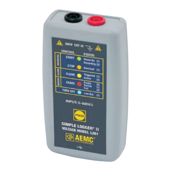
Page 11: Control Features
Control Features 2.2.1 Standard Models Figure 2-1 1. Input (model dependent) L101/L102 - BNC Input Termination L261/L481 - Two recessed 4mm safety banana jacks L111 - Two recessed 4mm safety banana jacks and fuse location L322/L432 - One 4-position removable screw-type terminal block L404 - One 8-position removable screw-type terminal block L562 - BNC/Two recessed 4mm safety banana jacks L642 - Two miniature thermocouple connectors... - Page 12 2. Five LED Indicators The LEDs on the logger serve two functions: Control Operation and Status Function. • The control operation (when holding down the PRESS button) is indicated with text to the left of each LED. • The status function (when PRESS is not being held down) associ- ated with each LED is indicated with text to the right of each LED.
-
Page 13: Clamp-On Model Cl601
2.2.2 Clamp-on Model CL601 INPUT: 0-600A 600V CAT III Figure 2-2 1. Safety barrier anti-slip guard For safety purposes, always hold the probe under the guard. 2. Control Button (PRESS) This button marked “PRESS” selects the mode of operation. Use this button to start or stop recordings, erase the memory and clear alarms. - Page 14 3. Five LED Indicators The LEDs on the instrument serve two functions: control operation and status function. • The control operation (function when holding down the PRESS button) is indicated with text to the left of each LED. • The status function (function when PRESS is not being held down) associated with each LED is indicated with text to the right of each LED.
-
Page 15: Specifications
CHAPTER 3 SPECIFICATIONS Reference Conditions: 23°C ± 3°C, 30-50% RH, DC or 50/60 Hz, no AC external magnetic field, DC magnetic field ≤ 40A/m, centered conductor, battery voltage: 3V ± 10%. MODEL L101 L102 ELECTRICAL Channels Input Input Level 0 to 1V Accuracy 0 to 10mV unspecified 10 to 50mV: ±(0.5% of Reading +1mV) - Page 16 MODEL L111 ELECTRICAL Channels Input Two recessed banana jacks Input Level 0 to 1A Accuracy 0 to 10mA unspecified (50/60Hz) 10 to 50mA: ±(0.5% of Reading +1mA) 50 to 1000mA: ±(0.5% of Reading +0.5mA) Resolution 0.1mA Maximum Input Current*** 1.2A Input Impedance Sample Rate 64 samples/cycle...
- Page 17 MODEL L261 ELECTRICAL Channels Input Two recessed 4mm safety banana jacks Input Level 0 to 600V AC/DC Accuracy 0 to 5V: unspecified (50/60Hz) 5 to 50V: ±(0.5% of Reading +1V) 50 to 600V: ±(0.5% of Reading +0.5V) Resolution 0.1V Maximum Input Voltage*** 1.2 x 600V Input Impedance 40MW...
- Page 18 MODEL L322 ELECTRICAL Channels Input One 4-position removable screw-type terminal block Input Level -20mA to +20mA Accuracy (0.25% of Reading +0.05mA) Resolution 0.01mA Maximum Input Current*** ±24mA Input Impedance Sample Rate Maximum of 8 samples taken at storage interval Storage Rate Programmable from 125ms to 1 per day Storage Modes Start/Stop, FIFO and Extended Recording Mode* (XRM...
- Page 19 MODEL L404 ELECTRICAL Channels Four Input One 8-position removable screw-type terminal block Input Level Contact closure, 0 to 5V Maximum Input Voltage*** Input Impedance >150KW Sample Rate Maximum of 8 per second Storage Rate Maximum once every two sample periods (event dependent) Storage Mode Event Recording Recording Length...
- Page 20 MODEL L432 ELECTRICAL Channels Input One 4-position removable screw-type terminal block Input Level Range 1: -100mV to 100mV Range 2: -1V to 1V (3 ranges/channel) Range 3: -10V to 10V Accuracy Range 1: ±(0.5% of Reading +1mV) Range 2: ±(0.5% of Reading +1mV) Range 3: ±(0.5% of Reading +10mV) Resolution Range 1: 0.1mV...
- Page 21 MODEL L481 ELECTRICAL Channels Input Two recessed 4mm safety banana jacks Input Level -850V to +850V Accuracy 0 to 5V: unspecified (50/60Hz) 5 to 50V: ±(0.5% of Reading +1V) 50 to 850V: ±(0.5% of Reading +0.5V) Resolution 0.1V Maximum Input Voltage*** ±1020V Input Impedance 40MW...
- Page 22 MODEL L562 ELECTRICAL Channels Connection Current Channel Voltage Channel Input Two recessed banana jacks Input Level 0 to 1V (for use with current 0 to 600V probes with a voltage output) Accuracy 0 to 10mV unspecified 0 to 5V unspecified 10 to 50mV: 5 to 50V: (50/60Hz)
- Page 23 MODEL L642 ELECTRICAL Channels Input Two miniature thermocouple connectors Measurement Range: °F °C (thermocouple dependent) -346 to +2192 -210 to +1200 -328 to +2501 -200 to +1372 -328 to +752 -200 to +400 -328 to +2372 -200 to +1300 -238 to 1742 -150 to +950 32 to 3212 0 to 1767...
- Page 24 MODEL L702 ELECTRICAL Channels Input Temperature Sensor Humidity Sensor Range 14° to 122°F (-10° to 50°C) 5 to 85% RH Accuracy ± (1% of Reading + 1°F/C) ±(3% of Reading + 2cts) Resolution 0.1°F/C 0.1% RH Sample Rate Maximum of 1 every 5 seconds Storage Rate Programmable from once every 5s to 1 per day Storage Modes...
- Page 25 MODEL ML912 ELECTRICAL Channels Input Captive MiniFlex AC Current Flexible Sensors ® Range 0.5 to 100A 5 to 1000A Accuracy 0 to 1A unspecified 0 to 5A unspecified 1 to 100A: 5 to 1000A: (50/60Hz) ±(1% of Reading + 0.5A) ±(1% of Reading + 1A) Resolution 0.1A...
- Page 26 MODEL CL601 ELECTRICAL Channels Input Split CT – AC Current Input Level 0 to 600A Accuracy 0 to 5A: Unspecified (50/60Hz) 5 to 50A: ±(1% of Reading +1A) 50 to 400A: ±(1% of Reading +0.5A) 400 to 600A for duration <10min: ±(3% of Reading +1A) Resolution 0.1A Maximum Input Current***...
-
Page 27: Operation
CHAPTER 4 OPERATION LED Control Operation and Status Function The ON/SLEEP state of the SLII can be determined by pressing the PRESS button for less than 0.5 seconds. If the instrument is ON, the status of the instrument will be shown by the LEDs. If the instrument is in SLEEP mode, all the status LEDs will light until the PRESS button is released. - Page 28 The Control and Status Operation of each LED is as follows: GREEN LED CONTROL Starts a Recording Single-blink Logger is in Standby Mode (and not recording) STATUS Double-blink Logger is in Record Mode ORANGE LED CONTROL Stops a Recording Logger is not in an Overload condition STATUS Single-blink One or more inputs are in an Overload condition...
-
Page 29: Connecting The Simple Logger ® Ii To A Computer
Overload occurs when any input is 10% above its input range. When the battery voltage goes below 1.7 volt the instrument will shut down (termi- nating and saving the recording, if it is recording). • SLEEP mode: The instrument enters the low power state if the button is not pressed for one minute. -
Page 30: Recording Data
There are two thresholds for the battery voltage: • The first is used to indicate low battery. The low battery indicator (Blue LED single blink) will blink when the battery voltage drops below 2.2V. The second is used to determine when to terminate recording and • turn the unit off. The shutdown threshold is when the battery voltage drops below 1.7V. -
Page 31: Stopping A Recording Session
4.3.2 Stopping a Recording Session 1. Press and hold the PRESS button. When the STOP (ORANGE) LED lights up, release the button. 2. The GREEN LED will change from a double-blink to a single-blink, indicating STANDBY mode. The data will be retained, even if the instrument is in sleep mode. The recorded data is stored in Flash memory (maintained even in the absence of batteries). -
Page 32: Erasing Data From Memory
Erasing Data from Memory Erasing data from the instrument’s memory can only be performed while in the STANDBY mode. There are two ways to erase the memory: Erasing the Memory using the PRESS Button: 1. Press and hold the PRESS button. When the ERASE (RED) LED lights up, release the button. -
Page 33: Data Storage
Data Storage The logger captures Trend measurements. The following are definitions of terms used in this section: Input Channel: Source for the measurement channel of the instrument. Measurement Channel: Measurement of input. This can be a simple direct measurement, the result of complex mathematical operations on a single or multiple input, or other channels. -
Page 34: Recording With Memory Cleared
4.8.1 Recording with Memory Cleared When a recording starts, the logger will continue to record until one of the following occurs: • The Session is complete. • The Memory is full and the recording mode is Start/Stop or Alarm. • The PRESS button is pushed until the STOP (ORANGE) LED lights up and is released before the next LED lights. -
Page 35: Batt. Power Insufficient For Full Record Duration
If in either the XRM or FIFO mode, the recording will continue even after memory becomes full. Memory will be freed to make room for new samples. The method of freeing memory will depend on the recording mode. 4.8.4 Battery Power Insufficient for a Full Recording Duration If the battery voltage drops below 1.7V, the following will occur: •... -
Page 36: Event Logger Operation (Model L404)
Event Logger Operation (Model L404) The Model L404 monitors up to four channels for the occurrence of events and stores information about each event. The rate at which each input is tested for the event status is defined by the sample period. Events that are shorter in duration than the period between sampling can potentially be missed. -
Page 37: Sample Event Capture
4.9.1 Sample Event Capture Figure 4-1 The above example assumes that the “Invert display polarity (event displayed as a high)” is selected from the scales tab of the configuration (default setting). 4.9.2 Application Examples Rain Gauge: Each time a tipping bucket fills and tips, a contact opens indicating that 0.1 inch of rain has filled the bucket. -
Page 38: 4.10 Reset Switch Operation
Sequencing: In a processing plant it has been determined that timing on several positions is out of specification. The service staff needs to know the sequence of valve opening and closing, and the duration of each, to correct the problem. The L404 can be connected to four outputs in the process and keep track of the time and duration of each opening and closing, thus providing the technician with the data they need to solve the sequence issue. -
Page 39: 4.11 Flash Upgrade Switches
It is recommended to only press the RESET button when the logger stops responding to a normal press button control when not connected to Data- View . It is not recommended to reset the instrument when the logger is ® recording, downloading or being configured. -
Page 40: Software Installation
Reader. This program is required to view DataView PDF documents. • The option DataView Update opens the AEMC website where you can check for the latest DataView software version releases. Similarly, Firmware Upgrades links to the website where you •... - Page 41 Click Finish to leave the InstallShield Wizard. You are now asked whether or not you would like to view instructions about how to connect the AEMC instrument or cable to the USB port on the computer. Click Yes to view these instructions, or No to proceed.
-
Page 42: 5.2 Data Logger Control Panel
You can access all DataView features through either the DataView icon or the Control Panel icon. For users who interact with a single type of AEMC instrument, we recommend primarily using the Control Panel. However, there are situations where using the core DataView icon may be more convenient for some users, such as when viewing multiple archived reports from different AEMC product families. -
Page 43: Maintenance
CHAPTER 6 MAINTENANCE Use only factory specified replacement parts. AEMC will not be held ® responsible for any accident, incident, or malfunction following a repair done other than by its service center or by an approved repair center. Replacing the Batteries CAUTION: Risk of electric shock. -
Page 44: Replacing The Fuse (Model L111)
Replacing the Fuse (Model L111) CAUTION: Risk of electric shock. Disconnect all input(s) from the unit or remove the clamp from any conductor before replacing the fuse. • With a flat-head screwdriver, twist the spring-loaded fuse holder one quarter turn counter-clockwise. •... -
Page 45: Appendix A: Troubleshooting
APPENDIX A TROUBLESHOOTING Symptom: After being in a damp, cold environment, the logger does not function. Cause, Correction: Condensation may have formed inside the logger, shorting out the circuitry and discharging the battery. Allow the circuit board to dry thoroughly in a warm location. Symptom: Simple Logger II does not start recording. -
Page 46: Appendix B: Glossary
APPENDIX B GLOSSARY Some general terminology associated with the data collection process is listed here for convenience. Bps: Bits Per Second, a unit of signal transfer speed equal to the number of elements per second. The Simple Logger II transfers data at ®... -
Page 47: Repair And Calibration
If the instrument is returned for calibration, we need to know if you want a standard calibration, or a calibration traceable to N.I.S.T. (Includes calibration certificate plus recorded calibration data). Ship To: Chauvin Arnoux , Inc. d.b.a. AEMC Instruments ® ®... -
Page 48: Limited Warranty
Instruments, not by the distributor from whom it was ® purchased. This warranty is void if the unit has been tampered with, abused or if the defect is related to service not performed by AEMC Instruments. ® Full warranty coverage and product registration is available on our website at www.aemc.com/warranty.html. - Page 49 Simple Logger II Series ®...
- Page 50 Simple Logger II Series ®...
- Page 51 Simple Logger II Series ®...
- Page 52 11/16 99-MAN 100309 v25 Chauvin Arnoux , Inc. d.b.a. AEMC Instruments ® ® 15 Faraday Drive • Dover, NH 03820 USA • Phone: (603) 749-6434 • Fax: (603) 742-2346 www.aemc.com...
Need help?
Do you have a question about the Simple Logger II and is the answer not in the manual?
Questions and answers