AEMC PEL102 User Manual
Power energy logger
Hide thumbs
Also See for PEL102:
- User manual (108 pages) ,
- Quick start manual (13 pages) ,
- Battery replacement procedure (10 pages)
Table of Contents
Advertisement
Quick Links
Download this manual
See also:
User Manual
Advertisement
Table of Contents

Related Manuals for AEMC PEL102


Summary of Contents for AEMC PEL102
- Page 1 PEL 102 POWER ENERGY LOGGER PEL 103 User Manual ENGLISH GlobalTestSupply www. .com Find Quality Products Online at: sales@GlobalTestSupply.com...
- Page 2 Thank you for purchasing a Power Energy Logger Model PEL 102 or PEL 103 For best results from your instrument and for your safety, read the enclosed operating instructions carefully and comply with the precautions for use. These products must be only used by qualified and trained users. WARNING, risk of DANGER! The operator must refer to Ethernet socket (RJ45).
-
Page 3: Table Of Contents
tabLE of contEnts 1. introDuction ......................5 1.1 Receiving Your Shipment ............................5 1.2 Ordering Information ...............................5 1.2.1 Accessories and Replacement Parts ......................6 2. ProDuct fEaturEs ..................... 7 2.1 Description ................................7 2.2 Front Panel Features ...............................8 2.3 Back Panel Features ...............................9 2.4 Lead Inputs ................................9 2.5 Installation of the Color-coded ID Markers ......................10 2.6 Connection Features .............................10... - Page 4 3.6.3.6 3-Phase 3-Wire Y (with 3 current sensors] ..................24 3.6.3.7 3-Phase 3-Wire ∆ Balanced (with 1 current sensor) ................25 3.6.4 3-Phase 4-Wire Y Power Networks ......................25 3.6.4.1 3-Phase 4-Wire Y (with 3 current sensors) ..................25 3.6.4.2 3-Phase 4-Wire Y Balanced .......................26 3.6.4.3 3-Phase 4-Wire Y 2½...
- Page 5 5. sPEcifications ......................70 5.1 Reference Conditions ............................70 5.2 Electrical Specifications ............................70 5.2.1 Voltage Inputs ............................70 5.2.2 Current Inputs ............................70 5.2.3 Accuracy Specifications (excluding current sensors) ................71 5.2.4 Current Sensors ............................74 5.2.4.1 Precautions for Use ...........................74 5.2.4.2 Use and Characteristics ........................74 5.2.4.3 MiniFlex MA193 ..........................74 ®...
-
Page 6: Introduction
1. introDuction 1.1 receiving Your shipment Upon receiving your shipment, make sure that the contents are consistent with the packing list. Notify your distributor of any missing items. If the equipment appears to be damaged, file a claim immediately with the carrier and notify your distributor at once, giving a detailed description of any damage. -
Page 7: Accessories And Replacement Parts
AC/DC Current Probe Model SL261 (10A-100mV/A, 100A-10mV/A, BNC) .............Cat. #1201.51 BNC adapter for SL261 current probe ......................Cat. #2140.40 Anti-theft Kensington Laptop Security Cable (available in most office supply stores) .............N/A DataView Software Updates are Available at www.aemc.com ® Power & Energy Logger Model PEL 102 and PEL 103 GlobalTestSupply www. -
Page 8: Product Features
2. ProDuct fEaturEs 2.1 Description PEL: Power and Energy Logger The PEL 102 and PEL 103 are simple-to-use, single, dual (split-phase) and three phase (Y, ∆) power and energy loggers. The PEL offers all the necessary functions for Power/Energy data logging for most of the 50Hz, 60Hz, and 400Hz and DC distribution systems worldwide offering numerous distribution set-ups. -
Page 9: Front Panel Features
2.2 front Panel features 1000V CAT III 600V CAT IV 1000V CAT III 600V CAT IV MODEL PEL 102 MODEL PEL 103 POWER & ENERGY LOGGER POWER & ENERGY LOGGER ON /OFF ON /OFF START/STOP START/STOP Figure 1 Four voltage input terminals. Three current input terminals. -
Page 10: Back Panel Features
2.3 back Panel features WARNING! Disconnect all inputs before opening the battery compartment Only replace with 8.4V NiMH custom battery pack Power Supply: 110-250V DC/AC 50/60Hz 30VA MADE IN FRANCE Figure 2 Four magnets (molded into the rubber casing). Six recessed Torx screws (for factory service use only). -
Page 11: Installation Of The Color-Coded Id Markers
For multiple-phase measurements, start by marking the accessories using the color-coded ID markers supplied with the device; a different color for each current terminal. Connect the measuring leads to your PEL as follows: ■ Current measurement: I1, I2, I3 4-point connectors ■... -
Page 12: Mounting And Location
2.7 Mounting and Location NOTE: Magnetic fields can damage hard drives and medical devices. The PEL should be placed in a well-ventilated room; temperature not to exceed those specified in § 5.5. The PEL 102 and PEL 103 can be mounted to a flat ferromagnetic vertical surface using the molded-in magnets. -
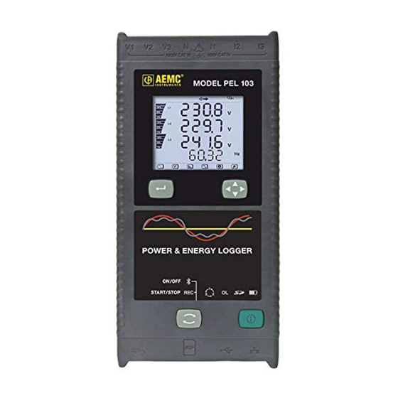
Page 13: Lcd Display (Pel 103)
2.10 LcD Display (PEL 103) Figure 7 Measured phase indicator. Bargraph (Load factor - Min - Max). The bargraph indicates the percentage (0% to 100%) of full range or full load as programmed into the PEL by the user through the DataView software. -
Page 14: Led Status
2.11 LED status ON /OFF START/STOP Figure 8 LED & COLOR STATUS Green LED: Recording Status LED blinks once per second every 5 s: Logger in standby (not recording) LED blinks twice per second every 5 s: Logger in recording mode Blue LED: Bluetooth LED OFF: Bluetooth OFF (disabled) LED ON: Bluetooth ON (enabled - not transmitting) -
Page 15: Memory Capacity
LED & COLOR STATUS Green LED: ON/OFF LED ON: External power supply present under LED OFF: No external power supply ON/OFF button Green LED: Ethernet LED OFF: No activity embedded in LED blinking: Activity the connector Yellow LED: Ethernet LED OFF: The stack failed to initialize or the Ethernet controller failed to initialize Blink Slow, toggle every second: The stack initialized properly Blink Fast, toggle 10 times per second: The Ethernet controller initialized properly embedded in... -
Page 16: Operation
3. oPEration 3.1 charging the battery Before the first use, start by fully charging the battery. ■ Connect the supplied power cord to the instrument and AC power. 1000V CAT III 600V CAT IV ■ The device will automatically turn ON. 120V ±... -
Page 17: Turning The Instrument On/Off
3.3 turning the instrument on/off 3.3.1 turning the PEL on To turn the PEL ON: ■ Connect the AC power supply cord to the PEL. ■ Connect the PEL to a power outlet. The PEL will turn ON automatically. ■ The GREEN LED under the ON/OFF button turns ON when the PEL is connected to a live supply source. -
Page 18: Starting/Stopping A Recording And Enabling Bluetooth
3.4 starting/stopping a recording and Enabling bluetooth Recordings are stored only on the SD card. To Start a Recording: ■ Insert the SD-card into the PEL. ■ Use the CONTROL button to start or stop a recording session and to enable or disable Bluetooth. ■... -
Page 19: Standby Mode (And Display Brightness)
■ When AC power is not present (power supply OFF or disconnected from a power supply), the instrument will run on battery power for approximately 30 minutes or less when Auto Power Off is enabled (see below). ■ The PEL has a built in Auto Power OFF: Auto Power Off can be set to 3 to 15 min or disabled) ■... -
Page 20: Bluetooth Connection To The Pel
3.5.6 bluetooth connection to the PEL The PEL 102 and PEL 103 are designed for a Bluetooth wireless connection to a computer. The Bluetooth connection can be used to configure the PEL, to prepare a recording session and to download recorded sessions. To communicate using the Bluetooth connection you will need a computer with Bluetooth capability. - Page 21 5. Once the instrument has been successfully added to the computer, a window similar to Figure 11 will be displayed. Select “Close”. Figure 11 6. Launch the PEL Control Panel using the icon placed on the desktop during the Dataview software installation, then ®...
-
Page 22: Distribution Systems And Pel Hook-Ups
3.6 Distribution systems and PEL Hook-ups This chapter describes how the current sensors and voltage test leads have to be connected to your installation according to its distribution system. The PEL shall also be configured (see § 4.4.3) for the selected distribution system. Source Load 3.6.1 single Phase 2-Wire... -
Page 23: 3-Phase 3-Wire Power Networks
3.6.3 3-Phase 3-Wire Power networks 3.6.3.1 3-Phase 3-Wire ∆ (with 2 current sensors) ∆ For 3-Phase 3-Wire measurements using two current sensors: ■ Connect the terminal V1 test lead to the L1 phase conductor ■ Connect the terminal V2 test lead to the L2 phase conductor ■... -
Page 24: 3-Phase 3-Wire Open ∆ (With 2 Current Sensors)
3.6.3.3 3-Phase 3-Wire open ∆ (with 2 current sensors) ∆ For 3-Phase 3-Wire Open measurements using two current sensors: ■ Connect the terminal V1 test lead to the L1 phase conductor ■ Connect the terminal V2 test lead to the L2 phase conductor ■... -
Page 25: 3-Phase 3-Wire Y (With 2 Current Sensors)
3.6.3.5 3-Phase 3-Wire Y (with 2 current sensors) For 3-Phase 3-Wire Y measurements using two current sensors: ■ Connect the terminal V1 test lead to the L1 phase conductor ■ Connect the terminal V2 test lead to the L2 phase conductor ■... -
Page 26: 3-Phase 3-Wire ∆ Balanced (With 1 Current Sensor)
3.6.3.7 3-Phase 3-Wire ∆ balanced (with 1 current sensor) ∆ For 3-Phase 3-Wire Balanced measurements using three current sensors: ■ Connect the terminal V1 test lead to the L1 phase conductor ■ Connect the terminal V2 test lead to the L2 phase conductor ■... -
Page 27: 3-Phase 4-Wire Y Balanced
3.6.4.2 3-Phase 4-Wire Y balanced For 3-Phase 3-Wire Balanced Y measurements using three current sensors: ■ Connect the terminal N test lead to the neutral conductor ■ Connect the terminal V1 test lead to the L1 phase conductor ■ Connect the terminal I1 current probe to the L1 phase conductor Ensure that the current arrow on the sensor is directed towards the load. -
Page 28: 3-Phase 4-Wire
3.6.5 3-Phase 4-Wire ∆ High Leg configuration. No Potential Transformer (Voltage Transformer) is connected; the installation under test is sup- posed to be a low voltage distribution system. 3.6.5.1 3-Phase 4-Wire ∆ ∆ For 3-Phase 4-Wire measurements and using three current sensors: ■... -
Page 29: Dc Power Networks
3.6.6 Dc Power networks 3.6.6.1 Dc 2-Wire For DC 2- Wire measurements: ■ Connect the terminal N test lead to the common conductor ■ Connect the terminal V1 test lead to conductor +1 ■ Connect the terminal I1 current probe to conductor +1 Ensure that the current arrow on the sensor is directed towards the load. -
Page 30: Dc 4-Wire
3.6.6.3 Dc 4-Wire For DC 4-Wire measurements and using three current sensors: ■ Connect the terminal N test lead to the common conductor ■ Connect the terminal V1 test lead to conductor +1 ■ Connect the terminal V2 test lead to conductor +2 ■... -
Page 31: Base Measurements - Displayed Values
3.7.1 base Measurements - Displayed Values The base measurements, or instantaneous readings, are displayed sequentially in screens showing all phases. The display sequence varies per type of power network. Table 4 shows the readings per network. ■ Each display is reached by pressing the ▲ or ▼ button. ■... -
Page 32: Energy - Displayed Values
3-Phase 3-Wire includes: ■ 3-Phase 3-Wire ∆ (with 2 current sensors) ■ 3-Phase 3-Wire ∆ (with 3 current sensors) ■ 3-Phase 3-Wire Open ∆ (with 2 current sensors) ■ 3-Phase 3-Wire Open ∆ (with 3 current sensors] ■ 3-Phase 3-Wire Y (with 2 current sensors) ■... - Page 33 press press press press press press press press Power & Energy Logger Model PEL 102 and PEL 103 GlobalTestSupply www. .com Find Quality Products Online at: sales@GlobalTestSupply.com...
- Page 34 Table 5 displays the LCD (PEL 103) sequence for each type of hook-up. The displays on the previous page show an example of the energy values for a 3-Phase 4-Wire network type. 1-Phase 1-Phase 3-Phase 3-Phase Step 2-Wire 2-Wire 3-Wire 3-Wire 3-Wire 4-Wire...
-
Page 35: Harmonic Display Values
3.7.3 Harmonic Display Values Table 6 displays the LCD (PEL 103) sequence for each type of hook-up. The displays on the left show an example of the harmonic values for a 3-Phase 4-Wire network type. 1-Phase 1-Phase 3-Phase 3-Phase Step 2-Wire 3-Wire 3-Wire... -
Page 36: Min/Max Display Values
3.7.4 Min/Max Display Values Table 7 displays the LCD (PEL 103) sequence for each type of hook-up. The displays on the left show an example of the min/max values for a 3-Phase 4-Wire network type. 1-Phase 1-Phase 3-Phase 3-Phase Step DC 2-Wire 2-Wire 3-Wire... -
Page 37: Information Display Values
3.7.5 information Display Values Step Value Units 1P-2W = 1-phase 2-wire 1P-3W = 1-phase 3-wire 3P-3W∆3 = 3-phase 3-wire ∆ (3 current sensors) 3P-3W∆2 = 3-phase 3-wire ∆ (2 current sensors) 3P-3W02 = 3-phase 3-wire Open ∆ (2 current sensors) 3P-3W03 = 3-phase 3-wire Open ∆... - Page 38 1st number = DSP firmware version 2nd number = Microprocessor firmware version Soft Version Scrolling serial number Serial N° (a label is also pasted inside the PEL on the main board) Table 8 Power & Energy Logger Model PEL 102 and PEL 103 GlobalTestSupply www.
-
Page 39: Pel Control Panel - Dataview Software
4. PEL controL PanEL - DataViEW softWarE ® For contextual information on using DataView, refer to the Help Menu within the software. 4.1 installing DataView DO NOT CONNECT THE INSTRUMENT TO THE PC BEFORE INSTALLING THE SOFTWARE AND DRIVERS. Minimum Computer Requirements: ■... - Page 40 2. A Set-up window, similar to the one below, will appear. Figure 30 There are several different options to choose from. Some options require an internet connection. ■ DataView, Version x.xx.xxxx - Installs DataView onto the PC. ■ *Adobe Reader - Links to the Adobe website to download the most recent version of Adobe Reader to the ®...
- Page 41 4. The Installation Wizard window will appear. Click Next. Figure 31 5. To proceed, click on the I accept the terms of the license agreement radio button, then click Next. Figure 32 Power & Energy Logger Model PEL 102 and PEL 103 GlobalTestSupply www.
- Page 42 6. In the Customer Information window, enter a Name and Company, then click Next. Figure 33 7. In the Setup Type window that appears, select the “Complete” radio button option, then click Next. Figure 34 Power & Energy Logger Model PEL 102 and PEL 103 GlobalTestSupply www.
- Page 43 8. In the Select Features window that appears, uncheck any instrument that you do not need to install and select only the instrument control panels that you do want to install, then click Next. Figure 35 The PDF-XChange option must be selected to be able to generate PDF reports from within DataView. 9.
- Page 44 10. If the instrument selected for installation requires the use of a USB port, a warning box, similar to below, will appear. Click OK. Figure 37 The installation of the drivers may take a few moments. Windows may even indicate that it is not responding, how- ever it is running.
-
Page 45: Connecting To A Pel
4.2 connecting to a PEL To connect to a PEL, perform the following steps: 1. Connect the power cord to an AC outlet. The instrument will power on. 2. Connect the supplied USB cable to the PEL and the PC. Wait for the drivers to finish installing before proceeding. 3. -
Page 46: Add An Instrument Wizard
4.2.1 add an instrument Wizard After choosing to Add an Instrument, the first dialog box of the Add an Instrument Wizard will be displayed: Figure 42 1. Click on the radio button associated with the desired connection type: ■ A local instrument connected to this computer with USB (see § 4.2.2) ■... -
Page 47: Usb Connection
4.2.2 usb connection The simplest and easiest connection to establish is a USB connection and is recommended when first learn- ing how to use the PEL and PEL Control Panel. The USB connection dialog box will list all of the USB instruments that are currently connected to the computer. Before continuing, make sure an instrument is connected to your computer using the supplied USB cable. - Page 48 The instrument will then be added to the PEL Network until it is removed (see § 4.3.4). Figure 45 If the instrument is already in the PEL Network (either with the same connection type or a different connection type) a dialog box will be displayed indicating this condition.
-
Page 49: Ethernet Network Connection
) on the LCD and use the ▼ button to scroll down to the IP Addr display screen (see § 3.7.5). For the PEL102, a USB or Bluetooth connection will need to be established to determine the IP address assigned to the instrument. -
Page 50: Bluetooth Connection
4.2.4 bluetooth connection NOTE: Bluetooth must be enabled (see §4.4.2) and turned on before a Bluetooth connection can be established. Figure 47 ■ From the Instrument drop-down list, select the desired instrument then click the Next button. ■ If a successful connection was established, the Finish button will be enabled. Click Finish to exit the Wizard (see Figure 44). -
Page 51: Pel Control Panel
4.3 PEL control Panel 4.3.1 opening and using the control Panel To open the PEL Control Panel: ■ Double-click the PEL icon that was created during installation, located on the desktop. ■ The Control Panel will be displayed. The Control Panel is used for instrument operation and configuration. Title Bar Menu Bar Navigation Tree... - Page 52 Create DataView Report: Generates a DataView report from the currently selected session. Export to Spreadsheet: Saves measurement data into an Excel spreadsheet. Print: Prints the current data display. Print Preview: Displays the current data display as it would look if printed. Print Setup: Opens the Print Setup dialog box allowing you to specify print options.
- Page 53 Help Topics: Displays the main Control Panel help topics. PEL Manual: Displays the user manual. Update: Connects to the AEMC website to determine the latest version of software and instrument firmware. About: Displays the About dialog box displaying version and copyright information.
-
Page 54: Modifying A Connection Type
4.3.2 Modifying a connection type To change or modify the connection type (e.g. from USB to LAN), select the desired PEL listed in the PEL Network, then select the Modify Connection Settings button ( ), located at the top of the Status area below the Toolbar. Figure 49 4.3.3 reconnecting and Disconnecting an instrument Disconnecting:... -
Page 55: Configuring The Pel
4.4 configuring the PEL 1. Open the PEL Control Panel by double-clicking the PEL icon that was created during installation, located on the desktop. The Control Panel will appear. 2. Connect to an instrument (see § 4.2). 3. Open the Configure Instrument dialog box by performing one of the following: ■... -
Page 56: General Options
4.4.1 General options The General tab of the Configure Instrument dialog box provides information about the instrument (Model and Serial number) and allows other instrument configuration options. Figure 55 Instrument Identification: ■ Model: Read only field that displays the model of the connected instrument. ■... - Page 57 Lock out the Control button on the instrument front panel: ■ When checked, locks the ON/OFF and CONTROL buttons. This can be useful to prevent unauthorized control of the instrument. Note that the ENTER and Navigation buttons (PEL103) are not locked. In addition to these options, there are two buttons allowing additional control of the instrument: ■...
-
Page 58: Communication Options
4.4.2 communication options The Communication tab of the Configure Instrument dialog box provides information about the various communication mediums supported by the instrument. Figure 56 Bluetooth: ■ Enable Bluetooth: When checked, enables the Bluetooth radio in the instrument. ■ Pairing code: Displays the pairing code that must be used when pairing the instrument to a computer. (pairing code cannot be modified). - Page 59 USB: ■ Name: Read only field that displays the name assigned to the USB interface. This is the name that will be displayed when adding the instrument via a USB connection. Network: ■ MAC address: Read only field indicating the MAC address of the network interface in the instrument. This can be used by a network administrator to assign an IP address to the instrument that is fixed via the DHCP server.
-
Page 60: Measurement Tab Options
4.4.3 Measurement tab options The Measurement tab of the Configure Instrument dialog box specifies the electrical distribution system, voltage ratios, nominal frequency and current probe options. Figure 57 Distribution system: ■ A box listing each of the distribution systems supported by the instrument (see §3.6 for available distribution systems descriptions). -
Page 61: Current Sensors And Ratios
The ratio between the specified primary and secondary will be used by the instrument for all related calculations. Phase-to-phase and Phase-to-neutral: Select either Phase-to-phase or Phase-to-neutral, depending on the selected distribution system, for each of the Primary and Secondary values. Note that some systems only allow one option. - Page 62 Secondary: Indicates the secondary current of the CT for the specified Primary current. The Primary and Secondary values establish a ratio used by the instrument when the probe is connected to the instrument. ■ Current Sensor with BNC Adapter: Nominal current: Indicates the current to be associated with the output voltage. Output voltage: Voltage that is applied to the BNC connector of the adapter for the specified Nominal current.
-
Page 63: Recording Tab Options
4.4.5 recording tab options The Recording tab of the Configure Instrument dialog box specifies various recording related options. Figure 58 Session: ■ Name: Field to assign a session name (40 characters max) to the recording session. Recording period: ■ Record Now: When checked, will start a recording when the OK button is pressed. ■... - Page 64 ■ Modify End Date/Time: This button is displayed when the instrument is actively recording. It allows you to change the ending time of the active recording. Trends Demand Interval: ■ Period: Drop-down list that allows the selection of one of the possible demand intervals supported by the instrument.
-
Page 65: Meters Tab Options
4.4.6 Meters tab options The Meters tab of the Configure Instrument dialog box specifies which of the instruments total accumulation meters are to be reset when the configuration is written to the instrument. Figure 59 Duration meters: ■ Reset total and partial energy meters: When checked, causes the total energy meters in the instrument to be reset. -
Page 66: Configuring And Recording Data Example
4.4.7 configuring and recording Data Example The following is intended as an example. You will configure the instrument to measure (and record) over a recording period of 8 hours. NOTE: Set the instrument’s clock to the proper time as the clock may vary due to time zones. 1. -
Page 67: Modifying An Instrument's Configuration
4.4.8 Modifying an instrument’s configuration To change or modify the instrument’s configuration, select the desired PEL listed in the PEL Network, then select the Modify Instrument Configuration button ( ), located at the top of the Status area below the Toolbar. Figure 62 4.5 Downloading recorded Data Recorded measurements stored in the instrument are transferred to a database on the PC using the download command. - Page 68 This opens the Download dialog box and begins the transfer of recorded data to the computer: Figure 66 ■ You can hide the Download dialog box by selecting the Close button. This does not stop the download but simply hides the Download dialog box so you can continue to use the PEL Control Panel. ■...
-
Page 69: Using The Cache
4.6 using the cache Downloaded sessions are saved to the cache, which is located in the “…\My document\DataView\Download\PEL\” folder. Sessions are cached so they do not need to be downloaded more than once. They are also saved so that if you exit the PEL Control Panel while downloading, the download can resume (where it left off) the next time the program starts. -
Page 70: Pel Reports
4.7 PEL reports Several predefined report templates are available for you to use. You can choose a report template either before or after a recording. You can also create your own custom templates. A report is created by performing the following steps 1. -
Page 71: Specifications
5. sPEcifications 5.1 reference conditions Parameter Reference Conditions Ambient temperature 73°F (23 °C) ± 2°F/C Relative humidity [45% RH; 75% RH] [100Vrms; 1000Vrms] Phase voltage without DC (< 0.5%) Input voltage of current inputs [50mV; 1.2V] without DC (< 0.5%) for AC measurement, without AC (< 0.5%) (except AmpFlex /MiniFlex for DC measurement... -
Page 72: Accuracy Specifications (Excluding Current Sensors)
5.2.3 accuracy specifications (excluding current sensors) SPECIFICATIONS at 50/60Hz Symbol Quantity Measurement Range Accuracy Frequency 42.5Hz < F < 69Hz ± 0.1Hz Phase-to-neutral 100V < V < 1000V ± 0.2% Rdg ± 0.2V Voltage Phase-to-phase 200V < U < 2000V ±... - Page 73 Symbol Quantity Measurement Range Accuracy Sin ϕ = 1 100V < V < 1000V ± 2% Rdg 5% < I < 120% I 0.5 inductive < Sin ϕ < 0.5 capacitive 100V < V < 1000V ± 2% Rdg 10% < I < 120% I Reactive Energy 0.5 inductive <...
- Page 74 SPECIFICATIONS @ DC Quantities Units Measurement range Accuracy Voltage 100V < V < 1000V ± 1% Rdg ± 3V Current 5% < I < 120% I ± 1% Rdg ± 0.3% I (DC without current sensor) 100V < V < 1000V Active Power ±...
-
Page 75: Current Sensors
5.2.4 current sensors 5.2.4.1 Precautions for use Refer to the safety sheet or user manual that was supplied with your current sensors for more information. 5.2.4.2 use and characteristics Current clamps and flexible current sensors are used to measure the current flowing in a cable without opening the circuit. They also insulate the user from dangerous voltages in the circuit. - Page 76 AmpFlex Sensors ® Nominal Range 100/400/2000/10000A Measurement Range 50mA to 12000A Length = 24" (610mm); Ø = 7.64" (190mm) Sensor Length = 36" (910mm); Ø = 11.46" (290mm) Safety EN 61010-2-032, Pollution Degree 2, 600V CAT IV, 1000V CAT III NOTE: Currents <...
-
Page 77: Accuracy
5.2.4.5 Accuracy The RMS current measurement accuracy and the phase accuracy correspond to addition values (which must therefore be added to the instrument’s accuracy), indicated as influences on the calculations carried out by the instrument (powers, energies, power factors, tangents, etc.). Typical error Maximum error Typical error... -
Page 78: Mechanical Specifications
5.4 Mechanical specifications Dimensions: 10.08 x 4.92 x 1.46" (256 x 125 x 37mm) Weight: < 1 kg Drop Test: 1 m in the most severe position without permanent mechanical damage and functional deterioration Degrees of Protection: Provided by enclosure (IP code) according to IEC 60529, IP 54) non-operating / not including terminals 5.5 Environmental specifications Altitude: Operating: 0 to 2000 m (6560 ft);... -
Page 79: Maintenance
NiMH factory supplied battery pack. Used batteries must not be treated as ordinary household waste. Recycle them appropriately. Use only factory specified replacement parts. AEMC will not be held responsible for any accident, incident, or malfunction ®... -
Page 80: Cleaning
Fax: (508) 698-2118 E-mail: techsupport@aemc.com 6.7 updating software & firmware To provide our customers the best possible service in terms of performance and technical upgrades, AEMC offers free ® software and firmware updates on our website. ■ Visit us at: www.aemc.com ■... -
Page 81: Limited Warranty
This limited warranty is given by AEMC Instruments, not by the distributor from whom it was purchased. This ® warranty is void if the unit has been tampered with, abused or if the defect is related to service not performed by AEMC ® Instruments. -
Page 82: Appendix A
aPPEnDiX a a.1 Measurements a.1.1 Definition Calculations are done according to IEC 61557-12 and IEC 61010-4-30. Geometric representation of active and reactive power: Source Load Export active power Import active power Import reactive power φ Export reactive power Source Load Figure 69 Diagram in accordance with clauses 12 and 14 of IEC 60375. -
Page 83: Locking Of Sampling Frequency
■ Main frequency f = 400Hz Inside 340 to 460Hz (400Hz ±15%), sampling period is locked to main frequency. 16 samples are available for each main cycle. Outside 340 to 460Hz, sampling period is 16*400Hz. DC is not a frequency parameter for sampling. A pure DC measured signal is considered to be outside the frequency ranges. -
Page 84: Energy Calculations
a.1.2.8 Energy calculations Energies are calculated every second. The “Total” energy is the demand during the recording session. The “Partial” energy can be determined during an integration period with the following values: 1 h, 1 day, 1 week, 1 month. The partial energy index is available only in real-time. -
Page 85: Aggregation
Quantities Formula Comments Cos φ [10/12] is the cosinus of the difference between the phase of the fundamental of the Cos φ current I and the phase of the fundamental of the line-to-neutral voltage V for 10/12 cycles values Q[10/12] and P[10/12] are the 10/12 periods TAN Φ... - Page 86 Quantities Formula − Reactive Power ∑ × on load (Q − ∑ Apparent Power (S × − Power Factor on source (PF ∑ × with associated quadrant − Active Power ∑ × on load (P − Reactive Power ∑ × on source (Q −...
-
Page 87: Supported Electrical Networks
a.4 supported Electrical networks The following types of distribution systems are supported: ■ V1, V2, V3 are the line-to-neutral voltages of the installation under test ■ [V1=VL1-N; V2=VL2-N; V3=VL3-N]. ■ Low caps v1, v2, v3 are used for time values ■... - Page 88 This method is named 2½ element method. Power measurement method is based on 3 wattmeters method with virtual neutral. Voltage measurements are performed between L1, L3 and N. see § 3.6.4.3 3-Phase 4-Wire Y 2½ 3P-4WY2 V2 is calculated: v2 = - v1 - v3, u12 = 2·v1 + v3, u23= - v1 - 2·v3. It supposes that V2 is balanced.
-
Page 89: Quantities According To The Supply Systems
a.5 Quantities according to the supply systems = YES 3P-3W∆2 3P-3W∆3 3P-4W∆ Quantities 1P-2W 1P-3W 3P-3WO2 3P-3WO3 3P-3W∆B 3P-4WY 3P-4WYB 3P-4WY2 DC-2W DC-3W DC-4W 3P-4WO∆ 3P-3WY2 3P-3WY3 ... - Page 90 3P-3W∆2 3P-3W∆3 3P-4W∆ Quantities 1P-2W 1P-3W 3P-3WO2 3P-3WO3 3P-3W∆B 3P-4WY 3P-4WYB 3P-4WY2 DC-2W DC-3W DC-4W 3P-4WO∆ 3P-3WY2 3P-3WY3 Source Source Source ...
- Page 91 3P-3W∆2 3P-3W∆3 3P-4W∆ Quantities 1P-2W 1P-3W 3P-3WO2 3P-3WO3 3P-3W∆B 3P-4WY 3P-4WYB 3P-4WY2 DC-2W DC-3W DC-4W 3P-4WO∆ 3P-3WY2 3P-3WY3 Hi_U Hi_U to 50 Hi_U ...
-
Page 92: Glossary Of Terms
a.6 GLossarY of tErMs Symbol or Terminology Description AC and DC components. AC component only. DC component only. Inductive phase shift. Capacitive phase shift. ° Degree. Percentage. Crest factor (Peak Factor) in current or voltage: ratio of the peak value of a signal to the RMS value. Cos ϕ... -
Page 93: Power & Energy Logger Model Pel 102 And Pel
Symbol or Terminology Description V-CF Voltage crest (peak) factor. Apparent power unit (Volt - Ampere). Reactive power unit. varh Reactive energy unit. V-THD Voltage crest (peak) factor. Phase-to-neutral voltage harmonic. True RMS phase-to-neutral voltage. V-THD Total harmonic distortion of phase-to-neutral voltage. Vunb Phase-to-neutral voltage unbalance. - Page 94 -11/12 Chauvin Arnoux , Inc. d.b.a. AEMC Instruments ® ® 15 Faraday Drive • Dover, NH 03820 USA • Phone: (603) 749-6434 • Fax: (603) 742-2346 www.aemc.com GlobalTestSupply www. .com Find Quality Products Online at: sales@GlobalTestSupply.com...
Need help?
Do you have a question about the PEL102 and is the answer not in the manual?
Questions and answers