Table of Contents
Advertisement
Quick Links
Advertisement
Table of Contents

Related Manuals for AEMC SENTINEL SDL-V301


Summary of Contents for AEMC SENTINEL SDL-V301
- Page 1 SDL-V301 SENTINEL™ DATA LOGGERS SDL-A301 SDL-A302 E N G L I S H User Manual...
- Page 2 Owner’s Record The serial number for the Sentinel™ Data Logger is located on the bottom side of the case. Please record this number and purchase date for your records. SENTINEL™ DATA LOGGER MODEL #: _______________________________________________ SERIAL #: _______________________________________________ PURCHASE DATE: ________________________________________ DISTRIBUTOR: ___________________________________________...
-
Page 3: Table Of Contents
Table of Contents 1. INTRODUCTION..............3 Warning ....................3 1.1 International Electrical Symbols.............3 1.2 Receiving Your Shipment...............3 1.3 Ordering Information ..............4 1.3.1 Accessories and Replacement Parts ........4 2. PRODUCT FEATURES ............5 2.1 Description ..................5 2.2 Control Features ................6 2.3 Inputs and Outputs.................7 3. - Page 4 5.3 Connecting to the Sentinel™ Logger ...........40 5.4 Using the Sentinel Control Panel ..........42 5.5 Configuring the Sentinel™ Logger..........45 5.5.1 Setting Recording Options ..........46 5.5.2 Setting Format Options ...........52 5.5.3 Configuring and Recording Data ........54 5.6 Displaying Real-time Status Information........57 5.7 Resizing and Saving Real-time Window Layouts ......59 5.8 Displaying Real-time Waveform Graphs ........60 5.9 Displaying Real-time Harmonic Bar Graphs ........62...
-
Page 5: Introduction
CHAPTER 1 INTRODUCTION Warning These safety warnings are provided to ensure the safety of person- nel and proper operation of the instrument. • Read the instruction manual completely and follow all the safety information before attempting to use or service this instrument. •... -
Page 6: Ordering Information
CD-ROM, user manual and warranty card. ® 1.3.1 Accessories and Replacement Parts Set of black and red leads with alligator clips....Cat. #2118.51 NEW: Order Accessories and Replacement Parts Directly Online Check our storefront at www.aemc.com for availability Sentinel ™ Data Loggers... -
Page 7: Product Features
CHAPTER 2 PRODUCT FEATURES Description The Sentinel Data Logger Models SDL-V301, SDL-A301 and SDL-A302 ™ are battery powered, three channel recording devices with an alkaline battery pack. Line tracking is performed such that 64 samples over one line cycle are taken. Frequency tracking is performed over the range of ±3Hz around the nominal line frequency (50 or 60Hz). -
Page 8: Control Features
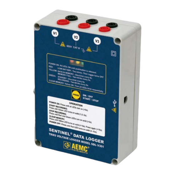
Control Features Figure 2-2. Key Components and Features 1. Control Button (Record Start/Stop) This button marked “PRESS” selects the mode of operation. The logger has three modes: RECORD, STANDBY and OFF. Use this button to start or stop recording and erase recording memory. 2. -
Page 9: Inputs And Outputs
3. Female Type B USB Connector 4. Reset Button (not shown) This button resets the CPU. The Reset Button is located inside the instrument under the shield. Remove the rear cover and insert a small tool, such as a pen, through the hole in the shield to activate it. -
Page 10: Specifications
CHAPTER 3 SPECIFICATIONS Sentinel Voltage Logger - Model SDL-V301 ™ ELECTRICAL All measurements are TRMS based on 64 samples per cycle. Range: 0 to 600V ; 0 to 850V Display Resolution: 0.1V Accuracy: ± (0.25% of Reading + 0.6V) from 85 to 600V (850V ±... - Page 11 RECORDING Storage Rate: 250ms to 12 hrs Recording Session Length: 1 minute to 8 weeks selectable from table or user programmable from computer Total Memory: Record 480,000 events (Size: 1MB) Date and Time: MM/DD/YY, DD/MM/YY, hh:mm:ss.sss (24hr and AM/PM) Storage Technique: Start/Stop, FIFO, XRM™ (Extended Recording Mode) INPUT Three sets of recessed banana jacks for voltage inputs for differential...
-
Page 12: Sentinel™ Current Logger - Model Sdl-A301
Sentinel Current Logger - Model SDL-A301 ™ ELECTRICAL All measurements are TRMS based on 64 samples per cycle. Range: 5 to 1000A Display Resolution: 0.1A Accuracy: ± (1.0% of Reading + 1.0A) from 100 to 1000A ± (1.0% of Reading + 1.2A) from 5 to 100A Accuracy specifications apply in the 23°C ±... - Page 13 INPUT Three current input using integrally wired flexible AmpFlex sensors. 64 ™ samples/cycle are taken to calculate TRMS value for each input. INTERFACE Output: USB 2.0 Compliant Isolation: Optically isolated, 5.5kVrms maximum Speed: 115.2 kbps MECHANICAL Dimensions: 6.73 x 4.76 x 2.17" (171 x 121 x 55mm) Weight: 3.2 lbs (1.4kg) including the batteries and AmpFlex sensors ™...
-
Page 14: Sentinel™ Current Logger - Model Sdl-A302
Sentinel Current Logger - Model SDL-A302 ™ ELECTRICAL All measurements are TRMS based on 64 samples per cycle. Range: 15 to 3000A Display Resolution: 0.25A Accuracy: ± (1.0% of Reading + 1.0A) from 100 to 3000A ± (1.0% of Reading + 1.5A) from 15 to 100A Accuracy specifications apply in the 23°C ±... - Page 15 INPUT Three Current input using integrally wired flexible AmpFlex sensors. 64 ™ samples/cycle are taken to calculate TRMS value for each input. INTERFACE Output: USB 2.0 Compliant Isolation: Optically isolated, 5.5kVrms maximum Speed: 115.2 kbps MECHANICAL Dimensions: 6.73 x 4.76 x 2.17" (171 x 121 x 55mm) Weight: 3.2 lbs (1.4kg) including the batteries and AmpFlex sensors ™...
-
Page 16: Operation
CHAPTER 4 OPERATION Operating Modes The Sentinel Logger has three modes: RECORD, STANDBY and OFF. ™ After the instrument has been turned on, the operating mode of the logger can be determined by pressing the PRESS button for less than 1.5 seconds. The GREEN LED indicates the mode of operation: LED OFF: Logger is turned off LED Single Blink: Logger is in Standby Mode (and not recording) - Page 17 Operations are determined by the length of time the control button is pressed. The lighting of each LED in sequence provides a visual indication that a required amount of time (for each operation) has been reached. The following table illustrates the operations that can be performed while in each of the three modes.
-
Page 18: Connecting The Sentinel™ To Your Computer
Connecting the Sentinel to your Computer ™ DO NOT CONNECT THE SENTINEL TO THE COMPUTER UNTIL THE SOFTWARE & DRIVERS HAVE BEEN INSTALLED. Figure 4-1 shows a typical hook-up. The Sentinel Data Logger utilizes an ™ optically isolated USB communication port. The manual for your computer should indicate where to find the USB port. -
Page 19: Recording Data
There are two thresholds for the battery voltage depending on how the instrument is turned ON (either button press or DataView ) and the record- ® ing state that it is in. • If the unit is turned ON from a button press, the threshold is 4.3V. -
Page 20: Downloading Recorded Data
To Stop Recording: 1. Push the PRESS button for >3s and <5s. The RED and GREEN LED will turn on simultaneously. 2. The GREEN LED will change from a double-blink to a single-blink, indicating STANDBY mode. The data will be retained, even if the instrument is turned OFF. The recorded data may be downloaded to a hard-disk. -
Page 21: Data Storage
Erasing the Memory using DataView ® 1. Connect the Sentinel to the computer and open the Control Panel for the Sentinel. 2. Select Erase Memory from the Instrument Menu. Data Storage The logger captures Trend measurements. We define the following terms: Input Channel: Source for the measurement channel of the instrument. -
Page 22: Normal Operation
Normal Operation Following is a detailed description of the logger operation. 4.8.1 Normal Operating Environment When the instrument is turned ON, the following occurs (provided there is sufficient battery voltage and no data is stored in the instrument’s memory): • The GREEN LED single-blinks. - Page 23 Control Panel from within DataView to check the available memory. ® Once the Memory has been cleared, or checked for sufficient memory, the logger is ready for a new Recording Session. There may be instances where the GREEN LED is also double-blinking indicating that the logger is still recording.
-
Page 24: Reset Button Operation
Event: Recording Session has Ended The logger will be in STANDBY mode, if one of the following occurs: • The Recording Session terminates due to recording end time being reached when recording in the Start/Stop mode. • The recording in Start/Stop mode fills the memory. •... - Page 25 Event: Pressing the RESET Button when a Recording has Ended • The RED LED will remain OFF. • The GREEN LED single-blinks. • The unit indicates that the memory is full (double-blinking YELLOW). Event: The Logger is Waiting for a New Recording Session If the RESET button is pressed when a recording has been scheduled, the logger will not start recording at the previously programmed date and time.
-
Page 26: Synopsis Of Operation
4.10 Synopsis of Operation Indicators Saved Data or Battery Recording ON, OFF Comments Session(s) in Voltage Session 1 - Single-Blink Note: P/B = Press Button Memory 2 - Double-Blink P/B Stops Recording. Pushing >10s does not erase the memory >3.8V Active during Recording. - Page 27 Turning the Unit On Unit off Press and Hold the PB 5 Seconds All LEDs on Bat low < 4.3V Red LED blinks twice PB released Cannot start a new All LEDs off recording under this condition Yellow LED blinks MEM full twice every 6 seconds STANDBY Mode...
- Page 28 Normal Operation Unit off STANDBY Mode No PC and PB In Recording The yellow LED for 5 min will be on if the memory is full and will not start a recording PB > 10 Sec 3 < PB < 10 Sec 1 <...
-
Page 29: Dataview Software
CHAPTER 5 DATAVIEW SOFTWARE ® DataView Software Installation ® DO NOT CONNECT THE SENTINEL TO THE PC BEFORE INSTALLING THE SOFTWARE AND DRIVERS. ® INSTALL THE DATAVIEW SOFTWARE BEFORE INSTALLING THE USB DRIVERS AND BEFORE ™ CONNECTING THE SENTINEL TO THE COMPUTER. Minimum Computer Requirements: •... - Page 30 Reader is required for viewing PDF documents supplied with ® DataView that are accessible from the Help menu. • *Software Updates - Links to the AEMC ® Software Update web- site to check for new software version releases. ® •...
- Page 31 3. Select the DataView, Version 2.03.xxxx option from the list, then click on Install. 4. The Installation Wizard window will appear. Click Next. Figure 5-2 5. In the Customer Information window, enter a Name and Company, then click Next. Figure 5-3 Sentinel ™...
- Page 32 Next. Figure 5-4 7. The Select Features window will appear. This allows features for all ® AEMC instruments compatible with DataView to be selected. ™ If only the Sentinel features are desired, uncheck all the boxes except for Sentinel.
- Page 33 8. In the Ready to Install the Program window, click on Install. Figure 5-6 NOTE: If installing the software onto a Windows XP system for the fi rst time, a warning dialog box will appear. 9. Click on OK to proceed. Figure 5-7 10.
- Page 34 ® NOTE: A warning dialog box will appear when installing on a Windows system, stating that the software has not passed Windows Logo testing. ® The drivers have been fully tested on Windows XP, so please select Continue Anyway to proceed. Figure 5-9 11.
- Page 35 Figure 5-11a Figure 5-11b NOTE: The Set-up window should still be open. You may now select ® another option to download (e.g. Adobe Reader), or you may close the window. ® Shortcuts for DataView and each instrument selected during the installa- tion process have been added to your desktop.
-
Page 36: Installing The Sentinel™ Usb Drivers
Installing the Sentinel USB drivers ™ DO NOT CONNECT THE SENTINEL TO THE COMPUTER UNTIL THE SOFTWARE & DRIVERS HAVE BEEN INSTALLED. You will only need to perform the following steps if you are asked to install ™ the drivers upon connecting the Sentinel to a USB port on the computer. - Page 37 3. The next window will state that you are installing software for a USB Composite Device (Figure 5-13). Select the “Install the software automatically” radio button option, then click Next. Figure 5-13 4. The Installation Wizard will begin to install the driver. Figure 5-14 Sentinel ™...
- Page 38 ® NOTE: A warning dialog box will appear when installing on a Windows system, stating that the software has not passed Windows Logo testing. ® The drivers have been fully tested on Windows XP, so please select Continue Anyway to proceed. Figure 5-15 5.
- Page 39 6. You have just fi nished installing the fi rst of two drivers to be installed. You will now install the driver for the USB to UART Bridge Controller. The next window (see below) will look identical to Figure 5-7 in Step 2 in this section.
- Page 40 ® Windows XP (pre SP2) ™ 1. Connect the Sentinel to a USB port on the computer. 2. The computer will automatically identify and install the correct drivers ™ and connect the Sentinel to your computer. 3. After a period of time, a warning dialog box will appear when installing ®...
- Page 41 ® Windows 98 SE, ME and 2000 ™ 1. Connect the Sentinel to a USB port on the computer. 2. After a period of time you will receive a message that New Hardware has been detected. 3. Windows ® will complete the driver installation process automatically. At this time you should be ready to go to the next section (§...
-
Page 42: Connecting To The Sentinel™ Logger
Connecting to the Sentinel Logger ™ There are two ways to connect to the Sentinel Logger: Connecting using the Sentinel Icon • Double-click the Sentinel Icon that was created during installation, located on the desktop. ® • DataView will open and the Connection window will appear (see Figure 5-18) NOTE: When connecting using the Sentinel icon and only one Sentinel is connected to the computer, it will be selected and a... - Page 43 ™ Once the desired Sentinel has been selected, click OK and the Sentinel Control Panel and Real-time windows will be displayed (See Fig 5-19) Figure 5-19 NOTE: The default layout can be changed by moving and resizing each window (see § 5.7 - Resizing and Saving Window Layouts) NOTE: Right-clicking on some areas inside a window will open a context window with descriptions of specifi...
-
Page 44: Using The Sentinel Control Panel
Using the Sentinel Control Panel The Control Panel is the primary access point for operating and confi guring ™ a Sentinel Logger. The Control Panel should still be open from the previous section. ™ (§ 5.3 - Connecting to the Sentinel Logger) If the Control Panel is not open, open it by clicking on the Control Panel option from DataView’s main Instrument menu. - Page 45 The following is a list of available main menu options: File Print - prints the status information. Print Preview - provides a preview of the information to be printed. Print Setup - displays a Print Setup window allowing you to select a destination printer and change various printing options.
- Page 46 Tools Colors - allows you to specify the default colors to be assigned to graph traces associated with specifi c trend measurements. Test Memory - this function performs a test to ensure that the memory is functioning properly. NOTE: This will take a little over a minute to complete. When testing, no operation within the Seninel’s Control Panel are pos- ™...
-
Page 47: Configuring The Sentinel™ Logger
Confi guring the Sentinel Logger ™ ™ To Confi gure the Sentinel Logger, perform the following steps: 1. Open the Control Panel and connect to an instrument (refer to the previous section if you are unsure how to open the Control Panel). 2. -
Page 48: Setting Recording Options
Figure 5-22 Storage Rate: Specifi es the rate at which sampled data is stored in the recording. Recording Mode: A list of three radio buttons that specify the mode in which the data is to be stored. • Start/Stop • FIFO •... - Page 49 Figure 5-23 The controls for specifying the Start/Stop date and time for the recording will be displayed. Figure 5-24 Sentinel ™ Data Loggers...
- Page 50 Recording Start: You can specify a start date and time by performing one of the following: • Select the Now button. This will set the Recording Start date and time to the current date and time plus two minutes. • Enter the start date and time in the associated edit boxes.
- Page 51 FIFO Recording Mode In the FIFO (First In First Out) mode, you only specify the starting date and time for the recording. The FIFO mode operates much like the Start/Stop mode with the excep- tion that the recording does not stop when memory becomes full. When this happens the oldest sample set is discarded to make room for the new sample set.
- Page 52 XRM Recording Mode In the XRM mode, you only specify the starting date and time for the recording. The XRM mode operates much like Start/Stop mode with the exception that the recording does not stop when memory becomes full. When this happens every other sample is discarded, memory is compacted and storage continues at 1/2 the storage rate.
- Page 53 COMMON RECORDING OPTIONS Regardless of the recording mode selected, the following buttons are available. Apply & Start Recording Now: Selecting this button will write the con- fi guration to the instrument and begin a recording provided memory is available in the instrument. Apply &...
-
Page 54: Setting Format Options
5.5.2 Setting Format Options The Format page is displayed by clicking on the Format tab. This page allows you to defi ne the following: Frequency: Specifi es the line frequency (50 or 60Hz) of the measurement inputs. Measurement Setup: Specifi es the measurement for each available channel. - Page 55 You can combine channels to perform more sophisticated math opera- tions. For example, you can use the math result of channel 5 as an option for channel 6. You must however, defi ne channels in order. You cannot defi ne channel 6 until channel 5 has been defi ned. The Format dialog page also has the following options: •...
-
Page 56: Configuring And Recording Data
5.5.3 Confi guring and Recording Data The following is intended as an example, which you can follow along. In this example you will be erasing the instruments memory. If the instrument contains important data that you wish to keep, refer to § 5.13 - Downloading Recorded Instrument Data before proceeding. - Page 57 Figure 5-28 10. Select the Format tab to display the Format page 11. Select the measurement frequency corresponding to your locality (50 or 60Hz). 12. Erase the instrument’s memory by clicking on Erase Memory. Click on the OK button. Figure 5-29 13.
- Page 58 To Save the Current Confi guration to Disk: • Select the Save Confi guration to File button. The Save As window will be displayed. • Specify a name for the fi le and type it into the File name fi eld, then specify a location where you would like to save it.
-
Page 59: Displaying Real-Time Status Information
Displaying Real-time Status Information Real-time data acquired from the instrument is displayed, in resizable fl oating windows using the Control Panel. Connect to an instrument and open the Control Panel, if it is not already open. Figure 5-30 The Control Panel window shows the Instrument Status information about the currently connected instrument. - Page 60 End Time - if the recording is of a Start/Stop type. Time Remaining - amount of time remaining for the current recording session (if one is active). Recording Mode - Start/Stop, FIFO or XRM. Storage Rate - the time between storage of sample sets. Database Status: Open or closed state of a database into which real-time measure- ments are to be or being stored.
-
Page 61: Resizing And Saving Real-Time Window Layouts
Resizing and Saving Real-time Window Layouts The placement and size of real-time windows can be changed. To move a window, click on and drag the title bar of a window to the desired position. To Move a Window, follow this example: 1. -
Page 62: Displaying Real-Time Waveform Graphs
Displaying Real-time Waveform Graphs Display a waveform window by selecting Waveform from the View menu. The real-time waveform window will be displayed as shown below. Figure 5-31 The Waveform Display window displays line cycle snapshots. This window displays the actual waveform relative to time. Displayed on the right side of this window, is a list of available channels. - Page 63 The real-time update can be paused by clicking on the Hold check box. When checked, the automatic update will stop until the check is removed. The Save button allows you to store the data into a database. (see § 5.12 - Saving Real-time Measurements) The Print button allows you to print the displayed waveforms.
-
Page 64: Displaying Real-Time Harmonic Bar Graphs
Displaying Real-time Harmonic Bar Graphs Display a harmonic bar graph window by selecting Harmonic Bar from the View menu. The real-time Harmonic Bar window will be displayed as shown below. Figure 5-32 The Harmonic Bar graph window shows the harmonic content of an asso- ciated line cycle using a bar graph. -
Page 65: Displaying Real-Time Harmonic Text Summary
5.10 Displaying Real-time Harmonic Text Summary Display a harmonic text summary window by selecting Harmonic Text from the View menu. The real-time Harmonic Text window will be displayed as shown below. Figure 5-33 The Harmonic Text display window shows the harmonic content of an associated line cycle using a tabular summary. -
Page 66: Displaying A Real-Time Trend Graph
5.11 Displaying a Real-time Trend Graph Display a trend graph window by selecting Trend from the View menu. The real-time Trend window will be displayed as shown below. Figure 5-34 The Trend Display window shows measurements (sample points) over a time period. -
Page 67: Saving Real-Time Measurements
5.12 Saving Real-time Measurements 5.12.1 Saving Waveforms and Harmonics Real-time data received from an instrument can be saved directly into a recording session database. This differs from the process of downloading and saving recorded data, in that the measurements are stored as the instrument measures them. These measurements are not necessarily being stored within the instrument. - Page 68 4. The Session Properties window will be displayed. Figure 5-36 The Session Properties window allows you to specify information about the recorded data. This information falls into three categories: • Operator Information: Information about the person performing the test. • Site information: Information about the place and facility where the test was performed.
- Page 69 5. Type the name of your company and your name into the Company and Operator fi elds, respectively, then select the OK button. ® 6. The main DataView window will be brought to the foreground and the Create View from Template window will be displayed. Figure 5-37 This window allows you to specify a template for the database that was just downloaded and saved.
-
Page 70: Saving Trend Graphs
5.12.2 Saving Trend Graphs To Save a Real-time Trend Graph, follow this example: 1. With the Control Panel open and a connection to the instrument established, if a Trend window is not already displayed select Trend from the View menu. 2. -
Page 71: Downloading Recorded Instrument Data
5.13 Downloading Recorded Instrument Data Recorded measurements stored in the instrument are transferred to a database on the PC using the download command. Assuming you started and stopped a recording session, the instrument should have at least one recorded measurement inside it. To Download a Recording, follow this example: •... -
Page 72: Sentinel™ Logger Templates
5.14 Sentinel Logger Templates ™ ® Refer to the DataView Help fi les for detailed information about using the Logger Templates. Trend AC Template The Trend V and A template is for use with the Voltage and Current log- gers and generates a view with two worksheets. You can move between the worksheets by selecting the desired worksheet from the worksheet tabs at the bottom of the view (just above the status bar). - Page 73 • Session Summary - containing operator comments. ® • OLE - containing the AEMC Instruments logo. Figure 5-42 Using the associated properties window customizes each of these frames. The properties window for a frame is displayed by selecting the frame, then selecting the Properties command from the Frame menu.
- Page 74 Trend Graph Frame A Trend Graph frame provides a graphical look into the database it is attached to. The database is attached to the Trend Graph frame when it is created. This frame provides additional tools for viewing the underlying database. These tools provide zoom and pan operations.
- Page 75 dragging the Zoom Tool across the desired area of the graph, you can select an area to zoom in on. Channel List Frame The Channel List frame is a child frame attached to either a Channel Graph, or Micro-Graph Frame. In the case of this template, the parent is a Trend Graph frame.
- Page 76 Meter Frame The Meter frame is a child frame attached to the Graph frame. The Meter frame displays the values of samples at a specific location on the graph. If you right click on the graph you will see a black vertical bar placed at the location you clicked.
-
Page 77: Maintenance
CHAPTER 6 MAINTENANCE Use only factory specified replacement parts. AEMC will not be held ® responsible for any accident, incident, or malfunction following a repair done other than by its service center or by an approved repair center. Battery Installation... -
Page 78: Appendix A: Troubleshooting
APPENDIX A TROUBLESHOOTING Symptom: After being in a damp, cold environment, the logger does not function. Cause, Correction: Condensation may have formed inside the logger, shorting out the circuitry and discharging the battery. Allow the circuit board to dry thoroughly in a warm location. Symptom: Sentinel™... -
Page 79: Appendix A: Glossary
APPENDIX B GLOSSARY Some general terminology associated with the data collection process is listed here for convenience. Bps: Bits Per Second, a unit of signal transfer speed equal to the number of elements per second. The Sentinel Data Logger transfers ™... - Page 80 Processor: a computing device used to calculate and run a set of instructions. Recording session: a recording session is defined as the time and data contained within the starting and ending of a recording. Resolution: the number of bits in which digitized value will be stored. The Sentinel Data Logger has 12-bit resolution.
-
Page 81: Repair And Calibration
If the instrument is returned for calibration, we need to know if you want a standard calibration, or a calibration traceable to N.I.S.T. (Includes calibration certificate plus recorded calibration data). Ship To: Chauvin Arnoux , Inc. d.b.a. AEMC Instruments ® ®... -
Page 82: Limited Warranty
Instruments, not by the distributor from ® whom it was purchased. This warranty is void if the unit has been tampered with, abused or if the defect is related to service not performed by AEMC ® Instruments. For full and detailed warranty coverage, please read the Warranty Coverage Information, which is attached to the Warranty Registration Card (if enclosed) or is available at www.aemc.com. - Page 83 07/05 99-MAN 100290 v4 Chauvin Arnoux ® , Inc. d.b.a. AEMC ® Instruments 15 Faraday Drive • Dover, NH 03820 USA • Phone: (603) 749-6434 • Fax: (603) 742-2346 www.aemc.com...
Need help?
Do you have a question about the SENTINEL SDL-V301 and is the answer not in the manual?
Questions and answers