Table of Contents
Advertisement
Quick Links
Advertisement
Table of Contents

Related Manuals for Elektron MULTISPOT MI-100control


Summary of Contents for Elektron MULTISPOT MI-100control
- Page 1 Made in Germany Operating Manual MULTISPOT MI-100control Resistance welder Item no.: 328 010 Be sure you have read and understood this operating Revision: 0.9 – Translation manual before you carry out any works on and / or with Version: 31. July 2013...
- Page 2 © BlitzRotary GmbH Branch Bremen Hinterm Sielhof 22 D-28277 Bremen Germany Phone: +49 (0)421 / 54 90 6 - 906 Fax: +49 (0)421 / 54 90 6 - 19 E-Mail: vertrieb@elektron-bremen.de Internet: www.elektron-bremen.de Release: BlitzRotary GmbH Branch Bremen...
-
Page 3: Table Of Contents
Resistance welder MULTISPOT MI-100control Table of contents Table of contents General Information ....................6 Information concerning the operating manual ................6 Copyright ........................... 6 Disclaimer ..........................6 Symbols ............................ 7 Warranty and guarantee ......................9 Customer service ........................9 Health and safety ....................10 Intended purpose ........................ - Page 4 Resistance welder MULTISPOT MI-100control Table of contents 4.4.1 Connections on the front side .................. 28 4.4.2 Connections on the backside .................. 29 Accessories ..........................30 4.5.1 Optional accessories ....................30 4.5.2 Tools required ......................30 Installation ......................31 Before installation ........................31 5.1.1...
- Page 5 Resistance welder MULTISPOT MI-100control Table of contents 6.7.2.2 Changing configuration ................61 6.7.2.3 Loading most recent configuration ............61 6.7.2.4 Storing all welding jobs ................62 6.7.2.5 Switching off weld rules ................63 6.7.2.6 Calling up status and error messages ............. 63 6.7.2.7...
-
Page 6: General Information
Resistance welder MULTISPOT MI-100control General Information General Information Information concerning the operating manual This operating manual will enable you to work efficiently and safely with this equipment. The manual is an essential part of this product and must be stored ready at hand not far from the equipment so that people can use it at any time without any problems. -
Page 7: Symbols
Resistance welder MULTISPOT MI-100control General Information Symbols Safety information This manual uses symbols to highlight important safety information. In addition, there is always a signal word heading the information indicating the severity of the danger or hazard that may be encountered. - Page 8 Resistance welder MULTISPOT MI-100control General Information Harmful substances! Danger of toxic, harmful vapours at least. Risk of stumbling! Risk of injury due to falls. Slip hazard! Risk of slipping due to leaking water. Prohibitions Electromagnetic fields! Hazard to persons with pacemakers.
-
Page 9: Warranty And Guarantee
Resistance welder MULTISPOT MI-100control General Information Tips, tricks and recommendations NOTE! ... highlights information that may be helpful to maintain efficient and trouble-free operation. Warranty and guarantee The guarantee conditions shall be as stipulated in the General Terms of Business of the manufacturer. -
Page 10: Health And Safety
This equipment has been designed and built for the following purpose(s), exclusively, and shall be used accordingly: The MULTISPOT MI-100control resistance welder serves the sole purpose of spot welding during maintenance work on car bodies, for stock of up to 3 mm sheet gauge and combinations of up to three sheets within its specifications and limits of use ( see “Specifications”). - Page 11 Resistance welder MULTISPOT MI-100control Health and safety During the entire lifetime of this equipment, the operating company must check in regular intervals whether such additional operating instructions are still up to date and must update them when necessary. The operating company must unambiguously determine and communicate responsibilities concerning the installation, operation, maintenance and cleaning of this equipment.
-
Page 12: Requirements To Personnel
The welder / operator has been coached / trained by employees of ELEKTRON and / or an authorised representative / dealer of ELEKTRON concerning his tasks and duties and possible hazards in connection with inappropriate behaviour and confirms this with his signature (see draft of training report form, “Appendix”). -
Page 13: Personal Protective Equipment (Ppe)
Resistance welder MULTISPOT MI-100control Health and safety 2.2.3 Personal protective equipment (PPE) CAUTION! Insufficient protection against injuries! Defective safety clothing may not constitute a proper protection against injuries. Therefore: Be sure to check PPE for integrity and good working condition before you start any works. -
Page 14: Particular Dangers
Resistance welder MULTISPOT MI-100control Health and safety Particular dangers 2.3.1 Dangers due to the equipment Electricity DANGER! Electricity constitutes a danger to life and limb! Touching live components can result in a fatal electrical shock. Therefore: As soon as you notice any damage to insulation, disconnect the power supply and have the damage repaired. - Page 15 Resistance welder MULTISPOT MI-100control Health and safety Splashes, flying sparks WARNING! Splashes and flying sparks constitute a danger of fire and explosion. Splashes and flying sparks pose a risk of injuries! Welding generates sparks and - hot spatter. They can ignite combustible materials and generate explosions.
-
Page 16: Dangers Due To The Work Environment
Resistance welder MULTISPOT MI-100control Health and safety 2.3.2 Dangers due to the work environment Vapours WARNING! Vapours may constitute a danger to your health! Stock that has not been properly ground and cleaned before welding may be contaminated with residues of glues, paints, undercoating products etc. that may generate harmful or even toxic vapours during welding. -
Page 17: Correct Behaviour In Accidents And Dangerous Situations
Resistance welder MULTISPOT MI-100control Health and safety Dangers to display and control panel CAUTION! Display and control panel may sustain damage! The display and control panel may sustain damage when being closed if negligent employees leave objects lingering on the accessory box beneath. -
Page 18: Safety Devices
Resistance welder MULTISPOT MI-100control Health and safety Safety devices WARNING! Danger! Due to insufficient protection against residual current! Connection to electrical socket: the device may only be plugged into a socket with a residual current device and an operable earthing device. -
Page 19: Safety Labels And Markings On This Equipment
Resistance welder MULTISPOT MI-100control Health and safety Safety labels and markings on this equipment 2.7.1 On the flap cover Meaning Welding generates electromagnetic fields. Electromagnetic fields pose a potentially fatal hazard to people with pacemakers or other magnetisable implants. Fig. 3: Warning sign “Electromagnetic fields” on... -
Page 20: On The Balancer
Resistance welder MULTISPOT MI-100control Health and safety 2.7.3 On the balancer Meaning Always pull in the direction the guiding wheels are pointing. In the event of lateral and / or transverse pull, there is a danger the wheels jam / block and the equipment tips over. -
Page 21: Waste Management And Environmental Protection
Resistance welder MULTISPOT MI-100control Health and safety Waste management and environmental protection CAUTION! Inexpert handling may constitute an environmental hazard! Inexpert handling of environmentally harmful substances, especially wrong disposal, may constitute a hazard to the environment. Therefore: Be sure to take appropriate measures whenever harmful substances get (or threaten to get) into the environment. -
Page 22: Transport, Packaging, Storage
Resistance welder MULTISPOT MI-100control Transport, packaging, storage Transport, packaging, storage Safety during transport Inexpert transport CAUTION! Improper transport may cause damage to property! Improper transport may cause damage to property. Therefore: When you unload packing units and move them across your premises, proceed with care. -
Page 23: Acceptance After Shipping
Resistance welder MULTISPOT MI-100control Transport, packaging, storage Acceptance after shipping Check packing units immediately after delivery. Check for integrity, missing pieces and damage. If you detect any external shipping damage, proceed as follows: Do not accept delivery; or accept under reserve. -
Page 24: Moving Equipment To The Site
Resistance welder MULTISPOT MI-100control Transport, packaging, storage 3.5.2 Moving equipment to the site When moving around, always grip equipment by the handle provided for that purpose. Fig. 10: Warning sign on balancer There is a danger of tilting CAUTION! Tipping and toppling may cause damage to property! This equipment’s centre of gravity is relatively high. -
Page 25: In Case Of Return Of Goods / Further Transport Needs
Resistance welder MULTISPOT MI-100control Transport, packaging, storage In case of return of goods / further transport needs 1. Drain cooling water tank completely. see “8.2.4”. 2. Use original transport pallet. (see Fig. 9) 3. Use packing materials that correspond to original packing materials. -
Page 26: Design And Functionality
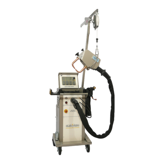
Fig. 11: MULTISPOT system (standard) Description The MULTISPOT MI-100control resistance welder has been designed and built with the special requirements of body makers and maintenance in mind. The inverter, which provides the power for welding, is controlled by a microprocessor. That way, weld current and weld time will be adjusted automatically on the basis of the selected operating mode, sheet gauge and welding job. -
Page 27: Display And Control Elements
Resistance welder MULTISPOT MI-100control Design and functionality Display and control elements 4.3.1 On the display and control panel Display see also Fig. 13 Selection elements see also Fig. 14 Touch key for power selection Touch key for selecting welding jobs... -
Page 28: On The Inverter Control Unit
Resistance welder MULTISPOT MI-100control Design and functionality 4.3.2 On the inverter control unit The power switch (Fig. 15) is for switching the power supply on and off. Fig. 15: Power switch (in „OFF” position) Connections 4.4.1 Connections on the front side Pressure gauge displays input pressure. -
Page 29: Connections On The Backside
Resistance welder MULTISPOT MI-100control Design and functionality 4.4.2 Connections on the backside Compressed-air filter unit Coolant-pump air supply Power cord Power switch Coolant outlet towards pump Coolant return Water filter Cooling-water tank cap Cooling-water tank Fig. 17: Connections on the backside... -
Page 30: Accessories
Electrode arms / hoops Electrode caps Fig. 18: Optional cooler 4.5.2 Tools required Key for electrode caps (Fig. 19) Fig. 19: Key for electrode caps NOTE! Find our complete range of products and order information at www.elektron-bremen.de. -
Page 31: Installation
Resistance welder MULTISPOT MI-100control Installation Installation Before installation 5.1.1 Preliminary works Check operating conditions according to specifications. see “9.4”.) If necessary, allow equipment time to adapt to ambient temperature SLOWLY. Make sure that operating company’s supply systems comply with specifications. -
Page 32: Ventin Coolant Circuit
Installation Venting coolant circuit CAUTION! Property damage due to heat build! The power unit of the MULTISPOT MI-100control is partially connected to the cooling circuit. Therefore: Before initial operation and after each filling of the coolant tank, the cooling circuit must be vented. -
Page 33: Assembling The Balancer
Resistance welder MULTISPOT MI-100control Installation Assembling the balancer 1. Unpack the balancer. 2. Check balancer components for damage. Use the checklist provided (Fig. 22) to check whether you have all the parts. — — — — Balancer — — — — Guide rollers with locking pin and ring —... -
Page 34: Electrical Connections
Resistance welder MULTISPOT MI-100control Installation Electrical connections Fig. 25: Power grid specifications CAUTION! Insufficient conductor cross-sections and fuse protection may make the grid collapse and / or trigger the fuses and make efficient welding impossible. Therefore: Before you connect the welder to the mains, make sure conductor cross-sections are sufficient (at least 6 mm²... -
Page 35: Connecting The Pneumatics
Resistance welder MULTISPOT MI-100control Installation Connecting the pneumatics 1. Take the supply line from the pneumatic grid of the plant and plug it on to the welder (Fig. 27). 2. The plant’s pneumatic mains must provide about 8 bar (116 Psi) input pressure to the welder. -
Page 36: Connecting The Pliers
Resistance welder MULTISPOT MI-100control Installation Connecting the pliers 1. Push the main plug of the welding pliers into the main socket of the equipment (Fig. 29/1.). 2. Turn the retainer nut clockwise (Fig. 29/2.) to lock the connection. Fig. 29: Connecting the pliers 3. -
Page 37: Connecting The Welding Gun
Resistance welder MULTISPOT MI-100control Installation Connecting the welding gun 1. Push the main plug of the welding pliers into the main socket of the equipment (Fig. 32/1.). 2. Turn the retainer nut clockwise (Fig. 32/2.) to lock the connection. 3. Unit will switch automatically and shows the “gun” symbol in the display. -
Page 38: Operation
Resistance welder MULTISPOT MI-100control Operation Operation Preliminary works before welding 6.1.1 Preparing the sheets Always connect the earth connection to the lower sheet. Otherwise the electricity cannot flow. When using insulating layers (e.g. spot welding primer), you must first establish an auxiliary connection (using a vise-grip wrench, for instance) in order to establish the electrical contact. - Page 39 Resistance welder MULTISPOT MI-100control Operation Exchanging electrode arms 1. To unbolt the electrode arm, use the Allen key provided for that purpose (Fig. 34). Fig. 34: Unbolting electrode arm 2. Remove the electrode arm simply by pulling it out. (Fig. 35).
- Page 40 Resistance welder MULTISPOT MI-100control Operation Deploying the electrode arm 1. Switch the locking device of the electrode arm / hoop from position “locked” (Fig. 37/A) to position “open” (Fig. 37/B) as shown in the picture. Fig. 37: Unlocking the arm / hoop Locking the electrode arm 2.
-
Page 41: Checks Before Switching On
Resistance welder MULTISPOT MI-100control Operation Aligning electrodes Be sure to look from different angles. Electrodes must align no matter how you look. Fig. 41: “Electrode must be in true alignment” Additional explanation on the welding plier, see separate operating manual. -
Page 42: Switching On
Resistance welder MULTISPOT MI-100control Operation Switching on 1. Once the welder has been installed and prepared according to instructions, you may switch it on by turning the power switch (Fig. 42). Fig. 42: Power switch If switching on has been successful, the display will show the following message: S07 “Powering up, please wait.”... -
Page 43: Basic Settings
Resistance welder MULTISPOT MI-100control Operation Basic settings 6.3.1 Set languages To set the display language, proceed as follows: 1. Switch off the welder. 2. Pull the plug of the welding pliers. 3. Switch on again. The display will show message “F35”. -
Page 44: Register Welder
Fig. 47: Menu item „Registering” The display shows the equipment info (Fig. 48). 2. Write down equipment ID and software version. 3. Go to the ELEKTRON website: www.elektron- bremen.de. Call up the “Product registration” page. Enter your data. 4. Fill in all the information in the online form in order to obtain the best possible service. -
Page 45: Recurring Settings
Resistance welder MULTISPOT MI-100control Operation Recurring settings 6.4.1 Maintaining electrode caps Whenever you switch on the welder and in regular intervals during operation, you will be reminded to take care of the electrode caps (Fig. 49). What to do: 1. Check the caps. If necessary, clean, mill or replace the caps. -
Page 46: Keyboard Operation
Resistance welder MULTISPOT MI-100control Operation 6.4.2.1 Keyboard operation For the welding job at hand, the following parameters may be set manually: Tool Sheet gauge Keyboard Program selectio Material, number of sheets , description Free mode Weld current Fig. 51: Selecting the control mode... -
Page 47: Setting Welder In Mode "Keyboard Operation
Resistance welder MULTISPOT MI-100control Operation 6.4.2.2 Setting welder in mode “Keyboard operation” 1. Use the control knob to select mode “Program selection”. Confirm. 2. Use a calliper gauge to measure the sheet gauges for the welding job at hand. 3. Determine the pertinent gauges for the job using the... -
Page 48: Oem Programs
Resistance welder MULTISPOT MI-100control Operation 6.4.2.3 OEM programs This mode contains a number of pre-set programs provided by OEMs. 1. Use the control knob to select mode Keyboard Program selectio “Program selection”. Confirm. Free mode Fig. 54: Selecting the control mode Next, the display will show a list of available welding programs (Fig. -
Page 49: Free Mode
Resistance welder MULTISPOT MI-100control Operation 6.4.2.4 Free mode This mode allows the welder to enter weld currents and times manually, and to store them as own programs. 1. Use the control knob to select the mode “Free mode”. Keyboard Program selectio Confirm. - Page 50 Resistance welder MULTISPOT MI-100control Operation Next, you will see a list of the current parameters in the display (Fig. 60). Actual values Folie MX MX4900 AØB4CØD4 Fig. 60: Parameters Modifying welding current (kA) 1. Press control knob. 2. Use the control knob to select “kA”. Confirm.
-
Page 51: Electrode Recognition
The display takes you back to the main menu. Fig. 66: Main menu 6.4.3 Electrode recognition The MULTISPOT MI-100control and the electrode arms are equipped with an automatic electrode recognition system. Electrodes are being identified automatically, and the length is shown on the display. -
Page 52: Manual Tool Selection
Resistance welder MULTISPOT MI-100control Operation The length of the electrodes will be displayed with a question mark. The contact force will be “0.0” (Fig. 68). Fig. 68: After acknowledgement Setting the electrode length manually: 1. Press the control knob to get into the enter mode. -
Page 53: Switching Off The Cooling Water Pump
Resistance welder MULTISPOT MI-100control Operation 6.4.5 Switching off the cooling water pump You may stop the cooling water pump and weld current at any time. Just press “Esc”. (E. g. to change the electrodes). After the pump has stopped, the display will shows the message “S09“... - Page 54 Resistance welder MULTISPOT MI-100control Operation Splashes, flying sparks WARNING! Splashes and flying sparks constitute a danger of fire and explosion. Splashes and flying sparks pose a risk of injuries! Welding generates sparks and –hot spatter. They can ignite combustible materials and generate explosions.
- Page 55 Resistance welder MULTISPOT MI-100control Operation There is a danger the equipment rolls away because the wheels must not be blocked due to the tipping and toppling hazard CAUTION! Equipment rolling away may cause damage to property! The wheels of the equipment must not be blocked because this would cause a tipping and toppling hazard.
- Page 56 Resistance welder MULTISPOT MI-100control Operation Adjusting the contact force NOTE! Be sure to set the correct contact force with respect to the current welding / OEM program selected – because: If the contact force of the electrodes is too high, the electrical resistance will be too weak which, in turn, will affect the welding job.
-
Page 57: Calling Up Welding Parameters
Settings in the service menu NOTE! The access and edit rights of some of the menus depend on the settings defined in ELEKTRON’s key file. If you should have any questions or need additional rights, please contact us. NOTE! Any service settings not described in this manual must be handled by skilled service personnel, exclusively. -
Page 58: Service Menu Settings
Resistance welder MULTISPOT MI-100control Operation 6.7.1 Service menu settings (page 1) Press service button on the control panel - once. This will call up the “Service” menu (page 1). 6.7.1.1 Enter order data Enter the order data under menu item “Enter order data”: Use the control knob to select “Enter order data”. -
Page 59: Administering Programs
Resistance welder MULTISPOT MI-100control Operation 6.7.1.3 Administering programs For organising and administering existing programs, use menu item “Administer programs”. Proceed as follows: Use the control knob to select “Administer programs”. Press to confirm. Loading individual programs from the CF memory card. -
Page 60: Setting Languages
Resistance welder MULTISPOT MI-100control Operation 6.7.1.7 Setting languages see “6.3.1” 6.7.1.8 Setting time and date Use menu item “Set date and time” to set the time and date. 1. Use the control button to select “Set date and time”. Press to confirm. -
Page 61: Changing Configuration
Resistance welder MULTISPOT MI-100control Operation You will see the message shown here on the left. Fig. 81: Cap service activated 6.7.2.2 Changing configuration Use the menu item “Change configuration” to carry out changes to the configuration. You need appropriate access rights. -
Page 62: Storing All Welding Jobs
Resistance welder MULTISPOT MI-100control Operation You can simply acknowledge the next prompt by selecting “OK”. You will see the message shown here on the left. Fig. 83: Loading last configuration 6.7.2.4 Storing all welding jobs Use the menu item “Save data on compact flash” to store data on the internal CF memory card. -
Page 63: Switching Off Weld Rules
Resistance welder MULTISPOT MI-100control Operation 6.7.2.5 Switching off weld rules Use the menu item “Switch off weld rules” to switch off the weld rules that have been pre-defined and stored in the system. However, you need the “Expert” CF memory card to accomplish this. -
Page 64: Calling Up The Software Version
Resistance welder MULTISPOT MI-100control Operation 6.7.2.7 Calling up the software version Use the menu item “Software version” to display the current version of the operating system. You need the data for troubleshooting and for ordering wear and spare parts. Use the control knob to select “Software version”. Press to confirm. -
Page 65: Modifying Service Address
Fig. 89: Modifying service address Updating software ELEKTRON software option for spot welding equipment CD-ROM + compact-flash memory card (CF memory card) Update by email (You will need a compact flash memory card reader.) Option: CD-ROM + CF card The CD-ROM contains the documentation explaining the use of the OEM weld programs. - Page 66 Resistance welder MULTISPOT MI-100control Operation Updating - proceed as follows 1. Switch off the welder. 2. Turn the knob on the left counter-clockwise (Fig. 90). 3. Swing out the control unit. Fig. 90: Open the front panel 4. Press the eject button to remove the CF memory card (Fig.
-
Page 67: Operating The Welding Gun
Resistance welder MULTISPOT MI-100control Operation Operating the welding gun 6.9.1 Push spot welding Caution! Electromagnetic fields! Wear protective goggles and gloves! Electrodes heat up! Flying sparks! Only use the mode “push spot welding” is the area to be welded cannot be reached with the spot welding pliers! 1. -
Page 68: Pulling-Out Dents With Washer
Resistance welder MULTISPOT MI-100control Operation 6.9.2 Pulling-out dents with washer 1. Grind the damaged area to a bright metal finish. 2. Insert contact piece U-B (Fig. 94) into welding gun. Fig. 94: Contact piece U-B 3. Select “washer” mode and sheet thickness on display. -
Page 69: High-Speed Planishing Hammer "Sah" (Special Accessory)
Resistance welder MULTISPOT MI-100control Operation 6.9.3 High-speed planishing hammer “SAH” (special accessory) Small dents, scratches or hail pitting can easily be removed with the high-speed planishing hammer. 1. Grind damaged area to a bright metal finish. 2. Insert high-speed planishing hammer (with weld on tip) into the gun (Fig. -
Page 70: Pushing-In Dents
Resistance welder MULTISPOT MI-100control Operation 6.9.4 Pushing-in dents Small high spots dents caused by overlapping load in the boot or by beating out with pulling tool can easily be flattened with contact piece (only for sheets up to 1 mm thickness). -
Page 71: Welding-On Threaded Studs
Welding-on threaded studs With the MULTISPOT MI-100control it is possible to weld on threaded studs of 4, 5, 6 mm diameter. Please use the appropriate contact pieces (SB 4 for Ø 4 mm / SB 5 for Ø 5 mm / SB 6 for Ø 6 mm) 1. -
Page 72: Welding-On T-Pins
Resistance welder MULTISPOT MI-100control Operation 6.9.7 Welding-on T-pins For example T-pins used for fixing trim strips, can be welded on using contact pieces TST 3 and TST 5 Incorporated in the tip of the contact piece is a magnet which holds the T-pin during the welding process. -
Page 73: Fixing Sheet Metal Parts (Tacking)
Body sections frequently have to be fixed temporarily for the purpose of alignment. In some areas, clamps cannot be used. In such cases, the sections can be fixed by tack welding with the MULTISPOT MI-100control. Washers from which ¼ has been cut out can be used as fixing aid. -
Page 74: Troubleshooting
Resistance welder MULTISPOT MI-100control Troubleshooting Troubleshooting Health and safety during troubleshooting WARNING! People with insufficient skills may suffer injuries! If you carry out troubleshooting and repairs yourself, you may encounter certain risks and hazards that may entail severe injuries. Therefore: Do not open the welder. - Page 75 Resistance welder MULTISPOT MI-100control Troubleshooting Who should Message What’s the problem What should be done? do it? The plug for measuring the Replace plug. Operator Pliers control not impedance at the front sheet has not connected. Please connect been connected.
- Page 76 Resistance welder MULTISPOT MI-100control Troubleshooting Who should Message What’s the problem What should be done? do it? The power section is overheated. Service personnel only. Service Power section is The fan is defective. overheated. – The plug of the temperature sensor Welder remains locked until has no contact.
- Page 77 Resistance welder MULTISPOT MI-100control Troubleshooting Who should Message What’s the problem What should be done? do it? The system has detected that a fuse However, you must Operator Reduce current by 5 %? was triggered. It is now possible to determine yourself whether reduce the weld current by 5 %.
-
Page 78: Problems Not Displayed On The Control Panel
Resistance welder MULTISPOT MI-100control Troubleshooting 7.2.2 Problems NOT displayed on the control panel Who should Message What’s the problem What should be done? do it? Welder does not boot up. Emergency stop pushbutton has Unlock pushbutton. Operator been pushed and is now locked. -
Page 79: Possible Causes And Remedies In Case Of Unsatisfactory Welding Results
Resistance welder MULTISPOT MI-100control Troubleshooting 7.2.3 Possible causes and remedies in case of unsatisfactory welding results WHO should Symptom Possible cause Remedy do it? Weld spot too small Weld current too weak. Adapt welding parameters. Operator If that doesn’t do it, fall back Weld time too short. -
Page 80: Maintenance
Resistance welder MULTISPOT MI-100control Maintenance Maintenance Maintenance schedule Who should Intervals What must be done? do it? Visually check the welder and its periphery for damage, dirt, contamination etc. Clean, if necessary ( see “8”). Check connections for tight fit. -
Page 81: Cleaning
Resistance welder MULTISPOT MI-100control Maintenance 8.2.1 Cleaning CAUTION! Failure to carry out and / or negligent or improper cleaning jobs may entail damage to property! If you do not clean the welder at all or use aggressive cleaning agents or –methods, there is a danger of damage to property. -
Page 82: Replacing Water Filter
Resistance welder MULTISPOT MI-100control Maintenance 8.2.3 Replacing water filter Scald hazard DANGER! Scalding may occur due to hot water coming out! While pulling out the cooling water hoses hot water may come out. Therefore: Wear gloves. Pull out water hoses carefully. -
Page 83: Empty Cooling Water Tank
Resistance welder MULTISPOT MI-100control Maintenance 8.2.4 Empty cooling water tank Scald hazard DANGER! Scalding may occur due to hot water coming out! While pulling out the cooling water hoses hot water may come out. Therefore: Wear gloves. Pull out water hoses carefully. -
Page 84: Measures To Be Taken After Maintenance
Resistance welder MULTISPOT MI-100control Maintenance Measures to be taken after maintenance When you finish maintenance and before you switch the welder back on, carry out the following: 1. Re-establish any and all connections you loosened and / or removed before. -
Page 85: Specifications
Resistance welder MULTISPOT MI-100control Specifications Specifications Dimensions and weights Item Value Unit Height 1100 /43 mm / in Width 690 /27 mm / in Depth 600 /23.6 mm / in Weight (w/o accessories) 100 / 220 kg / lb Power requirements... -
Page 86: Supplies
Resistance welder MULTISPOT MI-100control Specifications Supplies Item Value Unit Cooling water – tank capacity ca. 30 Chlorine-free disinfectant accor. dosing instructions Working conditions Ambient conditions Item Value Unit Ambient temperature, max. 40 / 104 °C / °F Rel Humidity, max. -
Page 87: Index
Resistance welder MULTISPOT MI-100control Index Index Emergency stop button ......... 18 Empty cooling water tank ........83 Environmental protection........21 Error messages ............. 74 Accessories ............30 Exposure limit values ..........86 Adjusting the distance between electrodes ..40 Airpuller ..............73 Ambient conditions .......... - Page 88 Resistance welder MULTISPOT MI-100control Index PPE ..............13, 55 Spring balancer ............ 33 Preparing the sheets ..........38 Storage ..............25 Preparing welding pliers ........38 Stumbling hazards ..........16 Problems Supplies ..............85 Switching off the cooling water pump ....53 not displayed on the control panel ....
-
Page 89: Appendix
Resistance welder MULTISPOT MI-100control Appendix Appendix 11.1 Training Report NOTE! Master copy. Do not fill in. Make copies. Date Name Type of training Trainer Signature... - Page 90 H i n t e r m S i e l h o f 2 2 D - 2 8 2 7 7 B r e m e n Phone +49 / (0)421 / 54 90 6-906 +49 / (0)421 / 54 90 6-19 vertrieb@elektron-bremen.de www.elektron-bremen.de...
Need help?
Do you have a question about the MULTISPOT MI-100control and is the answer not in the manual?
Questions and answers