
Related Manuals for Elektron MULTISPOT M20


Summary of Contents for Elektron MULTISPOT M20
-
Page 1: Operating Instructions
Operating instructions MULTISPOT M20 ELEKTRON Bremen GmbH Hinterm Sielhof 22 D-28277 Bremen - 1 - Fon +49/(0)421/54906-906 Fax +49/(0)421/5490619 vertrieb@elektron-bremen.de www.elektron-bremen.de... -
Page 2: Table Of Contents
Contents page 1.0 Warning notes – explanation of symbols 2.0 Description of equipment and overview 3.0 Start-up 3.1 Connection to power supply 3.2 Mains power supply connection 4.0 Applications 5.0 Technical data 6.0 Operating the welding gun 6.1 Pulling-out dents with washer 6.2 High-speed planishing hammer "SAH"... -
Page 3: Warning Notes - Explanation Of Symbols
1.0 Warning notes – explanation of symbols Caution! The power supply unit and leads of the welding gun and other tools generate a powerful electromagnetic field when in use. This can cause malfunctions in heart pacemakers, quartz watches and other electronic devi- ces. - Page 4 Tool selecting keys (manual) see Ap- pendix CD Gun functions selecting keys GH Fine adjustment keys time +/– Tools Special (e.g. AIRPULLER) Working with gun Welding of corrugated wire Stud welding/Copper shrinking Beat-out with washers, T-pins, Special High-speed planishing hammer M20 –...
-
Page 5: Description Of Equipment And Overview
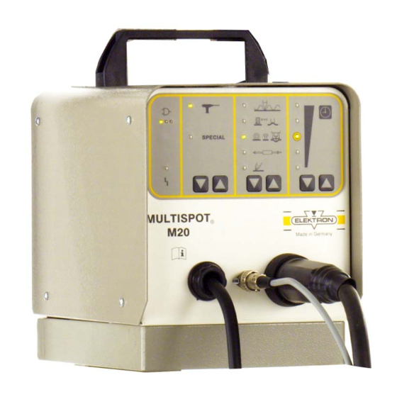
2.0 Description of equipment and overview The MULTISPOT M20 resistance welding unit is designed for the special requirements of motor vehicle body repair. The power source is controlled by a micro-processor. After selec- ting the operating mode, the current and weld time will be as- signed automatically. -
Page 6: Start-Up
16 A automatic circuit-breaker 3.3 Checking the mains voltage drop during welding If the full performance of the MULTISPOT M20 is to be obtained, the mains voltage drop during welding must be kept as small as possible. The full test is described on page 20 Chapter 8.3: ... -
Page 7: Applications
4.0 Applications Programme switch Material Max. sheet Function thickness in mm Dent-pulling with washer sheet steel T-pins 3 mm Ø sheet steel Dent-pulling with other tools sheet steel (e.g. Airpuller) Dent-pulling with high-speed planishing hammer sheet steel Shrinking sheet steel 0.6 - 1.0 Stud welding Steel bolts Ø... - Page 8 33 Welding gun 34 Button of welding gun 35 Grounding cable 36 Copper shoe 37 Lever clamp 38 Connection piece - 8 -...
-
Page 9: Operating The Welding Gun
6.0 Operating the welding gun Preparation: Insert the central plug of the welding gun (33) into the central socket (63) until limit stop. Arrow on the plug pointing up- wards. The unit will switch automatically to the "gun" symbol. ... - Page 10 40 Contact piece UB 41 Pulling tool - 10 -...
-
Page 11: Pulling-Out Dents With Washer
6.1 Pulling-out dents with washer Grind the damaged area to a bright metal finish. Insert contact piece (40) into welding gun. Select "washer" mode with keys CD. Fine-adjust +/– with keys GH, if necessary. Position welding gun (33) with washer in the area of the dent. - Page 12 42 High-speed planishing hammer "SAH", special accessory! - 12 -...
-
Page 13: High-Speed Planishing Hammer "Sah" (Special Accessory)
6.2 High-speed planishing hammer "SAH" (special accessory) Small dents, scratches or hail pitting can easily be removed with the high-speed planishing hammer (42). Grind damaged area to a bright metal finish. Insert high-speed planishing hammer (42) (with weld on tip) ... - Page 14 39 Carbon electrode 40 Contact piece U-B - 14 -...
-
Page 15: Pushing-In Dents
6.3 Pushing-in dents Small high spots dents caused by overlapping load in the boot or by beating out with pulling tool can easily be flattened with con- tact piece (40) (only for sheets up to 1 mm thickness). Insert contact piece (40) into the gun (33). ... - Page 16 44 Contact piece "threaded stud" - 16 -...
-
Page 17: Welding-On Threaded Studs
6.5 Welding-on threaded studs With the MULTISPOT M20 it is possible to weld on threaded studs of 4, 5, 6 mm diameter. Please use the appropriate contact pieces! SB 4 for Ø 4 mm SB 5 for Ø 5 mm ... - Page 18 45 Contact piece TST 3 Item no. 407 227 special accessory 47 T-pin 3 x 4.5 . Item no. 408 597 48 Fitting piece Golf 2 Item no. 313 451 special accessory 49 Fitting piece Passat B 3 Item no. 315 671 special accessory 50 Fitting piece Porsche Item no.
-
Page 19: Welding-On T-Pins
6.6 Welding-on T-pins For example T-pins used for fixing trim strips, can be welded on using contact pieces TST 3 (45) and TST 5 (52). Incorporated in the tip of the contact piece is a magnet which holds the T-pin during the welding process. ... - Page 20 - 20 -...
-
Page 21: Positioning/Fixing Sheet Metal (Tacking)
In some areas, clamps cannot be used. In such cases, the sections can be fixed by tack welding with the MULTISPOT M20. Washers from which ¼ has been cut out can be used as fixing aid. ... -
Page 22: Appendix/Self-Test And Troubleshooting
7.0 Appendix/self-test and troubleshooting 7.1 Self-test The MULTISPOT M20 is provided with a self-test program to check and evaluate the functions of the unit. 7.2 Checking the LED displays Detach the gun from the power supply unit. Connect the unit to the power supply. - Page 23 Self-test and evaluation For this purpose push button H in panel C longer than 2 seconds. LEDs in Panel A Indication code A 1) System fault EEPROM parameter – Call service. A 2) EEPROM operating – Call service. LEDs in Panel B B 1) Power inlet 230 V...
-
Page 24: Manual Tool Selection
7.4 Manual tool selection In an emergency or for service examination, it is possible to by- pass automatic tool recognition. Switch the unit OFF. Connect the tool to the unit. Switch the unit ON, depressing the tool key. ...
Need help?
Do you have a question about the MULTISPOT M20 and is the answer not in the manual?
Questions and answers