
Related Manuals for Elektron MULTIMIG 400puls


Summary of Contents for Elektron MULTIMIG 400puls
- Page 1 Operation Manual MULTIMIG 400puls ELEKTRON-BREMEN Fabrik für Elektrotechnik GmbH Postfach 10 59 60 D - 28059 Bremen Telefon +49 / (0)421 / 54 90 6-0 Telefax +49 / (0)421 / 54 90 619 vertrieb@elektron-bremen.de www.elektron-bremen.de...
-
Page 3: Safety Precautions
Secure the gas cylinder with a chain against falling over. 1 Safety precautions Please take off the gas cylinder from the machine for trans- Use and maintenance of welding and cutting portation. machines can be dangerous. Please draw Disconnect the plug from the mains before changing the user´s attention to follow the safety precau- welding area or repairs at the machine. -
Page 4: Technical Data
– TV / Radio VDE 0544-207. ELEKTRON recommends inspection periods – Computer and other similar devices of 12 months. – Protection devises as for example alarm systems A safety inspection must also be carried out after alterations or repair of the system. -
Page 5: Short Instructions
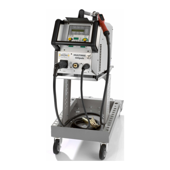
Type MULTIMIG 400puls Dimensions and weights Dimension power source (LxWxH) 745x340x498 Weight of power source A vers. Standard equipment Wire feed unit Rollers Wire diameter 1.0/1.2 Torch type ML 2400 PM 9 Short instructions Please refer to chapter 10 “Before operation” and Insert welding wire. -
Page 6: Torch Connection
How to connect at the mains 10 Before operation Plug in the plug into the mains socket. The fusing should be Torch connection corresponding to the technical data. Plug in the centralplug 17 of the torch 1 into the central socket How to insert the wirespool 16. -
Page 7: How To Connect The Gas Cylinder
How to modify the machine for aluminium welding Change the wire roll to a aluminium wire roll. Change the steel-torch against an aluminiumtorch or resp. change the wire liner against a teflon liner. Remove the capillary tube 42 at the central connection. Cut the teflon liner close to the end of the wire-feeding roll and correct contact... -
Page 8: Setting Into Operation
54 Digital multifunction display 11 Setting into operation For indication of the primary parameters such as welding DP 20 operating panel current, material thickness (in mm), wire feed speed (in m/min) or arc length correction. 43 44 46 47 48 49 50 51 55 “Primary parameter”... -
Page 9: Menu Structure
12 Menu Structure Main Level Level 1 Level 2 Remark Gas pre-flow 0 – 10 sec.; not in electrode mode Start current 20 % – 200 % of the welding current Start current time 0 – 10 sec.; not in 4-stroke mode Twin pulse frequency 0,5 –... -
Page 10: Extras Menu
Menu structure enter menuitem by pres- sing both keys 51 at the same time Gas pre-flow 1 Machine data Operating system Master Start current Operating system Process Start current time Operating system DMR change between me- Twin pulse frequency Welding programs nuitems with keys 48 (+) und 44 (-) Twin pulse current change... -
Page 11: Manual Mode
Selecting jobs: button 49. Switch the Tiptronic function on by pressing “Tiptronic” 49 Select the job number with the push-buttons 44 (-) and 48 (associated LED comes on). (+). Select the job number with the torch rocker (alternatively Press the push-buttons 51 at the same time (a the job number can be selected with the push-buttons 44 flashing cursor appears in the display 50) in order to get... -
Page 12: Error Codes
Error codes In case of a malfunction, an error code is indicated on the digital multifunction display 54 and the corresponding error description appears on the LCD display 50. As long as an error code is indicated, welding operation is not possible. Code Error description Remark Remedy... - Page 13 Types of arc 13 Basic of the MIG / MAG welding process Short circuit arc This type of arc is specially suitable for thin materials and po- Principle of the MIG / MAG welding sitional welding due to a relative cool welding pool welded The welding wire is fed from the wire coil to the contact tip due with very short arc, low arc voltage and low current.
-
Page 14: Holding And Manipulating The Torch
Holding and manipulating the torch Length of the wire electrode The distance between the torch and the workpiece should be Metal shielded gas welding can be welded in all posi- 10 – 12 times the diameter of the wire. Altering the distance tions: horizontal, vertical-down, vertical-up, overhead of the torch will influence the length of the electrode end. - Page 15 Material transfer Benefits: Pulse voltage U and pulse current I – Controlled, short-circuit-proof material transfer without Since welding with pulsed arc is based on the temporary uti- spatter lisation of the pinch effect, the drop-separating pulse current must always be large enough to exceed critical current inten- –...
-
Page 16: Care And Maintenance
Pulsed arc applications 15 Care and maintenance The main application for pulsed arcs is unalloyed steels within Please keep attention to the current safety regulations at all the performance range of the transition arc. At the lower end care and maintenance works. of the performance range the pulsed arc cannot fully replace the short-circuiting arc. - Page 17 Symptom Cause Remedy Less welding Phase missing Check the unit at another power outlet. Check performance power cable and mains fuses/circuit breakers Poor ground connection Ensure best contact between ground clamp and workpiece Ground cable not right plugged in Fasten ground cable by turning the plug to the right Defect torch Repair or replace it...
- Page 18 18 Service ELEKTRON-Bremen GmbH Postfach 10 59 60 D-28059 Bremen Germany Telefon: +49(0)421 54 90 6-0 Telefax: +49(0)421 54 90 6-19 Subject to change...
- Page 19 Appendix - mounting torch holder...
- Page 20 326601 06/05...
Need help?
Do you have a question about the MULTIMIG 400puls and is the answer not in the manual?
Questions and answers