Table of Contents
Advertisement
Quick Links
Advertisement
Table of Contents

Related Manuals for Elektron MULTIMIG 200


Summary of Contents for Elektron MULTIMIG 200
- Page 1 Made in Germany Operation Manual MULTIMIG 200 MIG / MAG - Welding machine Item-No: 327 973 Be sure you have read and understood this operating Revision: 1.0 - Original manual before you carry out any works on and/or with this Version: 31.01.2013...
- Page 2 © BlitzRotary GmbH Branch Bremen Hinterm Sielhof 22 D-28277 Bremen Germany Phone: +49 (0)421 / 54 90 6 - 906 Fax: +49 (0)421 / 54 90 6 - 19 E-Mail: vertrieb@elektron-bremen.de Internet: www.elektron-bremen.de Release: BlitzRotary GmbH Branch Bremen...
-
Page 3: Table Of Contents
MULTIMIG 200 Table of contents Table of contents Machine elements Start-up 13.1 Control console MULTIMIG 200 Explanation of symbols 13.2 Start-up Meaning of the symbols in the operation 13.3 Current / voltage display manual 13.4 Torch with remote control Meaning of the symbols on the machine 5 13.5... -
Page 4: Machine Elements
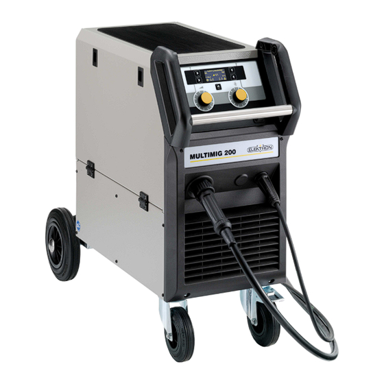
MULTIMIG 200 Machine elements Machine elements Fig. 1: Machine elements Safety chain for gas Hoisting points Mains cable Gas hose Tray area Handle Some depicted or described acces- Control panel sories are not included in the scope Main switch of delivery. -
Page 5: Explanation Of Symbols
MULTIMIG 200 Explantion of symbols – Safety precautions Explanation of symbols 2.1 Meaning of the symbols in the 2.2 Meaning of the symbols on the operation manual machine Danger to life and limb! Danger! If the danger warnings are disre-... -
Page 6: General Regulation Of Use
MULTIMIG 200 General regulation of use If the mains cable is damaged or Switch off the machine during breaks and severed in use, do not touch the close the valve of the gas cylinder. cable but unplug the mains plug Secure the gas cylinder with a chain to immediately. -
Page 7: Ambient Conditions
VDE 0544-4. ELEKTRON recommends inspection intervals of 12 months. The affected area can be bigger than your premises/property. This depends on the building, etc. -
Page 8: Setup And Transport
MULTIMIG 200 Setup and transport 10 Set-up and transport Danger of injury due to the de- vice falling over and crashing! When transporting using mechani- cal lifting equipment (e.g. crane, etc.), only the hoisting points shown here may be used. Use suitable load-carrying equipment. -
Page 9: Brief Operating Instructions
MULTIMIG 200 Brief operating instructions 11 Brief operating instructions Mode key 47 for selection of 2-stroke mode. A detailed description can be found in chapter. „Before start-up“ Page Key characteristics 50 and operation knob 10 and chapter. „Start-up“ Page 14. -
Page 10: Before Start-Up
MULTIMIG 200 Before start-up 12 Before start-up 12.3 Fastening the ground clamp 12.1 Connecting the torch Connect the central connector 17 of the torch to the central socket 11. Fig. 5: Correct Attach the ground clamp immediately be- side the welding point so that the welding Fig. -
Page 11: Insert The Welding Wire Spool
MULTIMIG 200 Before start-up Unscrew the contact tip of the torch. 12.4 Insert the welding wire spool Open side panel. Danger to life and limb and fire The diameter of the wire electrode must hazard due to glowing welding agree with the legible embossed figure on wire or parts! the wire feed rollers 25. -
Page 12: Connecting The Inert Gas Cylinder
MULTIMIG 200 Before start-up Set the insert gas cylinder 14 down on the carrier plate and secure it with the chain 1. Briefly open the gas cylinder valve 32 several times in order to blow out any dirt particles present. - Page 13 MULTIMIG 200 Before start-up Change the wire feed rollers. Select the Shorten the protruding plastic core so that it most suitable rollers for the application. is tight up against the wire feed roller, and slide the appropriately shortened support tube over the protruding plastic core for stabilisation.
-
Page 14: Start-Up
MULTIMIG 200 Start-up 13 Start-up 13.1 Control console MULTIMIG 200 Fig. 16: Control console MULTIMIG 200 Fig. 17: Graphic display... -
Page 15: Start-Up
MULTIMIG 200 Start-up Main switch for turning the welding 60 Display welding step displays the selected machine ON and OFF. welding step. 45 Turning knob for setting material 61 Display material thickness displays the thickness/welding voltage/welding step. selected material thickness of the workpiece in mm. -
Page 16: Current / Voltage Display
MULTIMIG 200 Start-up 13.3 Current / voltage display The actual values of welding voltage and welding current are displayed during and after welding (hold function). These values can be displayed individually or together on the graphic display. Possible display: Fig. 19:... -
Page 17: Characteristic Line
MULTIMIG 200 Start-up Fig. 20: Interval-welding deactivated Fig. 22: „noP“ (no program) Press key 46, 50 or 51 to end menu and return to standard display. Select a suitable welding step with turning knob 45. 13.6 Characteristic line 13.7 Mode Manual... -
Page 18: Tiptronic
MULTIMIG 200 Start-up Press key secondary parameter 46 or 51 to Activate Tiptronic open the secondary parameter menu. Press key menu 48. Select the required secondary parameter by Select menu option „Tiptronic“ by turning turning operation knob 52. operation knob 52. - Page 19 MULTIMIG 200 Start-up Fig. 26: safety question Fig. 28: edit job text Select „YES“ for overwriting the job by Press key mode 47 to edit numbers. turning operation knob 52. Press key secondary parameter 46 to edit Confirm „YES“ by pressing operation knob letters.
- Page 20 MULTIMIG 200 Start-up Press key 46, 50 or 51 to exit menu and return to standard display. Copying a job Press key Tiptronic 50. Select menu option „copy job“ by turning operation knob 52. Confirm menu option „copy job“ by pressing operation knob 52.
-
Page 21: Special Functions
MULTIMIG 200 Start-up 13.10 Special functions Gas test Turn the unit OFF using main switch 9. Press the torch key and keep it pressed. Turn the unit ON using main switch 9. The solenoid valve of the unit will go on and the gas supply can be tested / adjusted. - Page 22 MULTIMIG 200 Start-up Attention! All personal settings will be lost. welding secondary Attention! All Tiptronic-jobs will parameters are reset to their factory be deleted. set-tings. Fig. 35: Factory settings Fig. 36: Delete all jobs Select „YES“ by turning operation knob 52 to reset all values to factory settings.
-
Page 23: Menu Structure
MULTIMIG 200 Menu structure 14 Menu structure... - Page 24 MULTIMIG 200 Menu structure Main menu Level 1 Level 2 Note Sprache / Deutsch Language Select menu language English … Characteristics All settings can be performed independently Manual from a characteristic line. Depending on type of model are various SG 2/3 0,8 mm 82/18 characteristics set in the menu …...
-
Page 25: Messages
MULTIMIG 200 Messages 15 Messages In case of failure, a failure code is displayed in As long as there is an error code on graphical display 49. display welding is not possible. Code Error description Note Rectification Instead of material thickness „noP“ is displayed. -
Page 26: Troubleshooting
MULTIMIG 200 Troubleshooting 16 Troubleshooting Fault Possible cause Rectification Torch becomes too hot Contact tip not tightened properly check Torch switch has no function Union nut from torch hose pack to central Tighten the union nut when actuated socket is not correctly tightened... - Page 27 MULTIMIG 200 Troubleshooting Fault Possible cause Rectification Inert gas does not switch off Gas valve dirty or sticking Remove torch and pressure reducer, blow out the gas valve in the opposite flow direction with compressed air Inert gas feed insufficient...
-
Page 28: Repair And Maintenance
MULTIMIG 200 Repair and maintenance 17 Repair and maintenance Please heed the current safety Never make repairs or technical and accident prevention regu- changes yourself. lations during all maintenance In this case the manufacturer’s and repair work. warranty is no longer valid. -
Page 29: Technical Data
MULTIMIG 200 Technical data 18 Technical data Technical Data MULTIMIG 200 Welding range (I2 …I2 15…200 Welding range (U2 …U2 14,8…24,0 No-load voltage 14,4…32,5 Voltage setting Steps Slope characteristic constant voltage characteristic line ED 100 % ED 60 % ED at max. current Usable wires steel Ø... -
Page 30: Options And Accessories
MULTIMIG 200 Options and accessories 19 Options and accessories 19.1 Torch holder Fig. 37: Torch holder assembly left Fig. 38: Torch holder assembly right Order number: 420 958 Order number: 420 959 20 Disposal In accordance with European Council Directive Only for EU countries. -
Page 31: Schematic
MULTIMIG 200 Schematic 22 Schematic... - Page 32 H i n t e r m S i e l h o f 2 2 D - 2 8 2 7 7 B r e m e n Phone +49 / (0)421 / 54 90 6-906 +49 / (0)421 / 54 90 6-19 vertrieb@elektron-bremen.de www.elektron-bremen.de...
Need help?
Do you have a question about the MULTIMIG 200 and is the answer not in the manual?
Questions and answers